US4450331A - Key switch assembly having momentary closed interval - Google Patents
Key switch assembly having momentary closed interval Download PDFInfo
- Publication number
- US4450331A US4450331A US06/502,368 US50236883A US4450331A US 4450331 A US4450331 A US 4450331A US 50236883 A US50236883 A US 50236883A US 4450331 A US4450331 A US 4450331A
- Authority
- US
- United States
- Prior art keywords
- plunger
- switch
- camming
- column
- arm
- Prior art date
- Legal status (The legal status is an assumption and is not a legal conclusion. Google has not performed a legal analysis and makes no representation as to the accuracy of the status listed.)
- Expired - Fee Related
Links
- 230000000994 depressogenic effect Effects 0.000 claims abstract description 19
- 239000012528 membrane Substances 0.000 claims description 17
- 239000000758 substrate Substances 0.000 claims description 8
- 230000000712 assembly Effects 0.000 description 5
- 238000000429 assembly Methods 0.000 description 5
- 238000010586 diagram Methods 0.000 description 4
- 210000005069 ears Anatomy 0.000 description 4
- 239000000853 adhesive Substances 0.000 description 1
- 230000001070 adhesive effect Effects 0.000 description 1
- 230000002045 lasting effect Effects 0.000 description 1
- 239000000463 material Substances 0.000 description 1
- 239000002991 molded plastic Substances 0.000 description 1
- 230000003068 static effect Effects 0.000 description 1
Images


Classifications
-
- H—ELECTRICITY
- H01—ELECTRIC ELEMENTS
- H01H—ELECTRIC SWITCHES; RELAYS; SELECTORS; EMERGENCY PROTECTIVE DEVICES
- H01H13/00—Switches having rectilinearly-movable operating part or parts adapted for pushing or pulling in one direction only, e.g. push-button switch
- H01H13/50—Switches having rectilinearly-movable operating part or parts adapted for pushing or pulling in one direction only, e.g. push-button switch having a single operating member
- H01H13/506—Switches having rectilinearly-movable operating part or parts adapted for pushing or pulling in one direction only, e.g. push-button switch having a single operating member with a make-break action in a single operation
Definitions
- This invention relates to key switch assemblies of the type used on a keyboard for a computer or the like.
- the invention is particularly directed to the achievement of a key assembly which has an N key rollover feature.
- Keyboards of the type used with computers or electronic typewriters comprise a pluarlity of key switch assemblies, one assembly being provided for each key position on the keyboard.
- a normally open switch is associated with each key switch assembly so that when a particular key is depressed, the associated switch is closed.
- the switch may be a membrane switch and the pulses or signals produced by depression of the keys are interpreted by the circuitry to produce the desired result.
- the present invention is directed to the achievement of a key switch assembly which has the N key rollover feature purely by virtue of its mechanical features so that it is unnecessary in the use of the keyboard to provide N key rollover features in the integrated circuits with which the keyboard is used.
- a key switch assembly in accordance with the invention comprises a panel-like support, a pair of spaced-apart switch contacts on the support at a switch site and a frame on the support proximate to the switch site.
- the frame comprises a column extending normally of the support having a fixed end and a free end.
- a plunger is provided on the column which is normally maintained in an extended position relative to the support by a biasing spring and which is movably towards the support to a depressed position.
- a switch closing lever is pivotally mounted on the frame and is movable in response to movement of the plunger. The closing lever is effective electrically to connect the switch contacts to each other when it is moved.
- the key switch assembly is characterized in that the switch closing lever is a bell crank having a pivotal axis, a switch closing arm, and a cam follower arm.
- the pivotal axis is adjacent to the switch site and extends parallel to the plane of the panel-like support.
- the switch closing arm extends from the pivotal axis towards the switch site and has a free end which is proximate to, but normally spaced from, the switch contacts.
- the camming arm extends from the pivotal axis beside the plunger and has a free end which is spaced from the pivotal axis.
- the camming arm has a cam follower portion thereon.
- the plunger has a stiffly flexible camming rod extending from the upper end thereof towards the lower end.
- the camming rod has a camming portion which is angularly spaced from the cam follower portion of the camming arm, relative to the axis of the plunger, and which is moved past the cam follower portion during movement of the plunger to the depressed position.
- a cam deflector is provided on the frame proximate to the cam follower portion of the camming arm. The cam deflector has a deflecting surface which is engaged by the camming portion of the camming rod when the plunger is moved to the depressed position.
- the deflecting surface causes flexing of the camming rod laterally towards the cam follower portion of the camming arm with resulting engagement of the cam follower portion by the camming portion of the camming rod and resulting arcuate movement of the bell crank whereby the free end of the switch closing arm is moved towards the switch contacts and causes closing of the switch.
- the deflecting surface is of limited extent so that the camming rod returns to its normal position when the camming portion moves past the deflecting portion with resulting movement of the free end of the switch closing arm away from the switch contacts and opening of the switch.
- the switch contacts are thus electrically connected to each other only during a brief interval during movement of the plunger from the extended position to the depressed position.
- the switch contacts are opposed contacts on the substrate and the flexible membrane of a membrane switch.
- the switch closing lever is movably against the flexible membrane during movement of the plunger to the depressed position and is effective to flex the membrane towards the substrate and thereby engage the switch contacts with each other.
- the frame has a base, the fixed end of the column is integral with the base, and the pivotal axis of the bell crank is in the base proximate to the fixed end of the column.
- the column has an axially extending opening therein extending from the fixed end to the free end and the plunger is slidably contained in the axially extending opening.
- FIG. 1 is a perspective exploded view showing the essential parts of a key switch assembly in accordance with the invention.
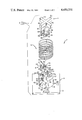
- FIG. 2 is a cross-sectional view of the key switch assembly showing the positions of the parts immediately after the beginning of the downward stroke of the plunger.
- FIG. 3 is a view of a cam provided on the frame column for camming a camming rod into engagement with a switch closing lever.
- FIG. 4 is a diagram showing the movement of the plunger of a key switch assembly during a complete stroke of the key.
- FIG. 5 is a diagram showing the condition of the switch during the stroke of a key switch assembly in accordance with the invention.
- FIG. 6 is a diagram similar to FIG. 5 but showing the condition of the switch with a conventional prior art key switch assembly.
- a key switch assembly 2 in accordance with the invention comprises a frame 3, the plunger 4, a biasing spring 6, a switchclosing lever 8, and a key top 10 which is mounted on the upper end of the plunger 4.
- the frame may be of molded plastic material and comprises a base 12 having a column 14 extending therefrom.
- the column has a lower or fixed end 16, an upper free end 18, and an axially extending opening 20 extending therethrough from the free end through the fixed end and throughthe base 12.
- the column has oppositely facing side surfaces 22, 24 and end surfaces 26. Slots 28, 30 are provided in the side surfaces 22, 24 and communicate with the axially extending opening 20.
- the end surfaces 26 arestepped adjacent to the free end 18 as shown at 32 and slots 34 are provided in these end surfaces which extend from the free end 18 to the surfaces 32.
- the slots 28, 30, 34 receive radially extending arms on the upper end of the plunger 4 as will be described below.
- the plunger comprises a cruciform plunger shaft 36 having oppositely directed projections 38, 40 and oppositely directed projections 41.
- the projections 38, 40 have upwardly facing shoulders 42 adjacent to the lowerend 43 of the plunger for cooperation with downwardly facing shoulders 44 in the column 14.
- the shoulders 44 are proximate to the free end 18 of thecolumn and the plunger can be assembled to the column by forcing the shaft portion thereof into the axially extending opening until the shoulders 42 are beneath the shoulders 44.
- the biasing spring 6 is mounted on the base 12 in surrounding relationship to the column 14 and bears against the arms46, 48, 50, 52 as shown in FIG. 2.
- arms 46-52 extend radially from the upper or outer end of the plungerand are received in a recess in the under side of the key top 10, the arrangement being such that when the plunger is moved to its fully depressed position, portions of the arms 46-52 will be received in the slots 28, 30, 34.
- a stiffly flexible camming rod 54 extends from the underside of the arm 48 and has an inwardly turned end portion 56 which functions as a cam follower in a manner described below.
- a cam 58 is provided on the side 24 of the column adjacent to the slot 30.
- the camming rod is normally locatedwith its axis offset from the center line of the slot 30 and a deflecting surface 60 on the cam 58 engages the end 56 of the camming rod during an initial portion of the downward stroke of the plunger.
- the deflecting surface causes the camming rod to be flexed so that the inwardly turned end 56 engages the camming portion 84 of the switch closing lever as described below.
- the switch closing lever 8 is essentially a bell crank having a U-shaped mounting portion 64 that has parallel spaced apart ears 66, a switch closing arm 76, and a camming arm 78.
- the U-shaped portion 64 is received in an opening 68 in the base 12 of the frame and is pivotally mounted on its pivotal axis by means of opposed bosses 72 on ears 70 which are provided on each side of the opening.
- the ears 66 of the closing lever have inwardly formed bosses 74 which when formed, produce spherical recesses in the ears 66.
- the recesses conform to the bosses 72 so that thebell crank switch closing lever can be moved in either direction about the pivotal axis.
- the arms 76, 78 extend through an opening 86 in the side 24 of the column 14 and the switch closing arm 76 has a free end 80 which is substantially against the upper surface of a flexible membrane.
- the camming arm 78 is reversely formed as shown at 82 so that it extends alongside the plunger and towards the upper or free end 18 of the column. Clearance is provided for the camming arm by a slot 88 in the projection 40 of the shaft portion36 of the plunger.
- the camming arm 78 Adjacent to its upper end, the camming arm 78 has a camming portion 84 which projects through the slot 30 and beyond the plane of the side surface 24 of the column. This camming portion is located such that it is engaged by the inwardly directed portion 56 of the camming rod 54 as this inwardly directed portion moves downwardly from the position shown in FIG.2.
- the portion 56 of the camming rod engages the camming portion 84, the bell crank is swung through a slight clockwise arc and when the inwardly directed portion 56 moves past the cam 58, the camming rod returns to its normal position and the bell crank will be returned to its normal position.
- the key switch assembly 2 is shown as being mounted above switch electrodes98, 100 on the substrate 90 and the flexible membrane 96 of a membrane switch.
- the substrate is separated from the flexible membrane by a separator 94 and the substrate in turn is supported on a rigid panel-like support 92.
- the membrane and substrate will usually extend over the entire area of the keyboard with switch electrodes at each key site.
- the key is secured in position by adhesive as shown at 102.
- the camming rod moves past the cam 58 as explained above and the surface 60 causes deflection of the camming rod sothat its inwardly turned end 56 engages camming portion 84 of the actuator lever 8.
- the actuator lever is swung through a slight arc and the electrodes 100, 98 are moved into contact with each other.
- the switch immediately opens and the parts return to their normal positions.
- the amount of force required to close the switch is very slight and the amount of force on thearm 76 to return the bell crank to its normal position is also very slight.
- the bell crank is returned by the membrane 2. If desired, domes can be provided on the membrane to assist in returning the bell crank to its normal position.
- FIGS. 4-6 show the performance of a key switch assembly in accordance with the invention as compared with a conventional key switch assembly.
- FIG. 4 is a diagram illustrating the movement of the plunger from the extended position to the fully depressed position and back to the extended positionwhen the operator depresses the key.
- the associated membrane switch is open during most of this interval and is closed for only a brief interval while the plunger is being moved to its depressed position.
- the actual interval of switch closure will vary to some extent but can be as little as 3 milliseconds.
- the switch can be caused to close at the beginning of the downward stroke of the plunger rather than towards the end of the downward stroke of the plunger.
Landscapes
- Push-Button Switches (AREA)
Abstract
Description
Claims (9)
Priority Applications (1)
| Application Number | Priority Date | Filing Date | Title |
|---|---|---|---|
| US06/502,368 US4450331A (en) | 1983-06-08 | 1983-06-08 | Key switch assembly having momentary closed interval |
Applications Claiming Priority (1)
| Application Number | Priority Date | Filing Date | Title |
|---|---|---|---|
| US06/502,368 US4450331A (en) | 1983-06-08 | 1983-06-08 | Key switch assembly having momentary closed interval |
Publications (1)
| Publication Number | Publication Date |
|---|---|
| US4450331A true US4450331A (en) | 1984-05-22 |
Family
ID=23997491
Family Applications (1)
| Application Number | Title | Priority Date | Filing Date |
|---|---|---|---|
| US06/502,368 Expired - Fee Related US4450331A (en) | 1983-06-08 | 1983-06-08 | Key switch assembly having momentary closed interval |
Country Status (1)
| Country | Link |
|---|---|
| US (1) | US4450331A (en) |
Cited By (3)
| Publication number | Priority date | Publication date | Assignee | Title |
|---|---|---|---|---|
| US4553009A (en) * | 1982-09-03 | 1985-11-12 | Oak Industries Inc. | Keyboard switch with pivotal actuator lever |
| US4642433A (en) * | 1984-07-11 | 1987-02-10 | Alps Electric Co., Ltd. | Pushbutton switch with aural confirmation of operation |
| US5444203A (en) * | 1991-11-01 | 1995-08-22 | Asea Brown Boveri Ab | Safety switch for an industrial machine |
Citations (4)
| Publication number | Priority date | Publication date | Assignee | Title |
|---|---|---|---|---|
| US3367206A (en) * | 1965-06-10 | 1968-02-06 | Westinghouse Electric Corp | Pushbutton actuator |
| US3566705A (en) * | 1968-02-14 | 1971-03-02 | Telephone Mfg Co Ltd | Push button keys |
| US3931911A (en) * | 1971-12-06 | 1976-01-13 | King-Seeley Thermos Co. | Ice dispensing machine |
| DE2848567A1 (en) * | 1977-12-30 | 1979-07-05 | Alps Electric Co Ltd | PUSH BUTTON SWITCH WITH A LEAF SPRING |
-
1983
- 1983-06-08 US US06/502,368 patent/US4450331A/en not_active Expired - Fee Related
Patent Citations (4)
| Publication number | Priority date | Publication date | Assignee | Title |
|---|---|---|---|---|
| US3367206A (en) * | 1965-06-10 | 1968-02-06 | Westinghouse Electric Corp | Pushbutton actuator |
| US3566705A (en) * | 1968-02-14 | 1971-03-02 | Telephone Mfg Co Ltd | Push button keys |
| US3931911A (en) * | 1971-12-06 | 1976-01-13 | King-Seeley Thermos Co. | Ice dispensing machine |
| DE2848567A1 (en) * | 1977-12-30 | 1979-07-05 | Alps Electric Co Ltd | PUSH BUTTON SWITCH WITH A LEAF SPRING |
Cited By (3)
| Publication number | Priority date | Publication date | Assignee | Title |
|---|---|---|---|---|
| US4553009A (en) * | 1982-09-03 | 1985-11-12 | Oak Industries Inc. | Keyboard switch with pivotal actuator lever |
| US4642433A (en) * | 1984-07-11 | 1987-02-10 | Alps Electric Co., Ltd. | Pushbutton switch with aural confirmation of operation |
| US5444203A (en) * | 1991-11-01 | 1995-08-22 | Asea Brown Boveri Ab | Safety switch for an industrial machine |
Similar Documents
| Publication | Publication Date | Title |
|---|---|---|
| US4095066A (en) | Hinged flyplate actuator | |
| US5057657A (en) | Electrical switch actuator mechanism | |
| US5510584A (en) | Sequentially operated snap action membrane switches | |
| US4440515A (en) | Keybar keyboard | |
| US5280147A (en) | Keyswitch assembly with a key support limiting transverse, longitudinal and rotational movement of the key | |
| US6218635B1 (en) | Push and rotary operating type electronic device | |
| US5442152A (en) | Computer key switch | |
| EP0142593B1 (en) | Keyboard switch with pivotal actuator lever | |
| US5278374A (en) | Assembly with an asymmetrical resilient spring | |
| KR101312136B1 (en) | Switch Responsive to See-saw Key | |
| US4417115A (en) | Switch actuating assembly having improved cams and plural modes | |
| US3940578A (en) | Keyboard structure having panel mounted key actuators with electrical component operating element | |
| US20020027062A1 (en) | Push-button switch and multiple switch using the same | |
| US5430267A (en) | Keyboard switch | |
| US5004880A (en) | Click-type push button switch with improved leaf spring | |
| US4952762A (en) | Keyboard switch | |
| US4181826A (en) | Dome switch actuating apparatus | |
| US4978818A (en) | Key for a circuit board | |
| US4931605A (en) | Multi-pole switch | |
| US6774330B2 (en) | Multi-stage push button switch apparatus | |
| US5012055A (en) | Spring loaded push-button switch having predictable switching time despite varying spring characteristics | |
| US4450331A (en) | Key switch assembly having momentary closed interval | |
| CA1160269A (en) | Pushbutton key switch | |
| EP1133720B1 (en) | Keyboard for an electronic device | |
| CA2437332A1 (en) | Depression switch and multidirectional input device |
Legal Events
| Date | Code | Title | Description |
|---|---|---|---|
| AS | Assignment |
Owner name: AMP INCORPORATED P.O. BOX 3608 HARRISBURG, PA 171 Free format text: ASSIGNMENT OF ASSIGNORS INTEREST.;ASSIGNOR:FUKUKURA, KAZUTOYO;REEL/FRAME:004140/0955 Effective date: 19830520 |
|
| FEPP | Fee payment procedure |
Free format text: PAYOR NUMBER ASSIGNED (ORIGINAL EVENT CODE: ASPN); ENTITY STATUS OF PATENT OWNER: LARGE ENTITY |
|
| FPAY | Fee payment |
Year of fee payment: 4 |
|
| AS | Assignment |
Owner name: AMP KEYBOARD TECHNOLOGIES, INC., A WHOLLY OWNED SU Free format text: ASSIGNMENT OF ASSIGNORS INTEREST.;ASSIGNOR:AMP INCORPORATED;REEL/FRAME:005258/0518 Effective date: 19890418 Owner name: LUCAS DURALITH AKT CORPORATION Free format text: CHANGE OF NAME;ASSIGNOR:AMP KEYBOARD TECHNOLOGIES INC.;REEL/FRAME:005258/0527 Effective date: 19890428 |
|
| REMI | Maintenance fee reminder mailed | ||
| REMI | Maintenance fee reminder mailed | ||
| REMI | Maintenance fee reminder mailed | ||
| LAPS | Lapse for failure to pay maintenance fees | ||
| FP | Lapsed due to failure to pay maintenance fee |
Effective date: 19920524 |
|
| STCH | Information on status: patent discontinuation |
Free format text: PATENT EXPIRED DUE TO NONPAYMENT OF MAINTENANCE FEES UNDER 37 CFR 1.362 |