EP0095367B1 - Schnelles Evakuieren für Hochvakuumbearbeitung - Google Patents
Schnelles Evakuieren für Hochvakuumbearbeitung Download PDFInfo
- Publication number
- EP0095367B1 EP0095367B1 EP19830302950 EP83302950A EP0095367B1 EP 0095367 B1 EP0095367 B1 EP 0095367B1 EP 19830302950 EP19830302950 EP 19830302950 EP 83302950 A EP83302950 A EP 83302950A EP 0095367 B1 EP0095367 B1 EP 0095367B1
- Authority
- EP
- European Patent Office
- Prior art keywords
- processing
- processing chamber
- cooled surface
- pumping
- workpiece
- Prior art date
- Legal status (The legal status is an assumption and is not a legal conclusion. Google has not performed a legal analysis and makes no representation as to the accuracy of the status listed.)
- Expired
Links
- 238000005086 pumping Methods 0.000 claims description 20
- 235000012431 wafers Nutrition 0.000 claims description 15
- XLYOFNOQVPJJNP-UHFFFAOYSA-N water Substances O XLYOFNOQVPJJNP-UHFFFAOYSA-N 0.000 claims description 7
- 239000002245 particle Substances 0.000 claims description 5
- 239000004065 semiconductor Substances 0.000 claims description 5
- 238000004891 communication Methods 0.000 claims description 3
- 238000005259 measurement Methods 0.000 claims description 2
- 230000036961 partial effect Effects 0.000 claims description 2
- 230000005855 radiation Effects 0.000 claims description 2
- 239000002826 coolant Substances 0.000 claims 3
- 239000007789 gas Substances 0.000 claims 1
- 230000001678 irradiating effect Effects 0.000 claims 1
- 238000010943 off-gassing Methods 0.000 description 7
- 238000000034 method Methods 0.000 description 6
- 230000008569 process Effects 0.000 description 6
- 238000005468 ion implantation Methods 0.000 description 5
- 229920000642 polymer Polymers 0.000 description 5
- 230000009467 reduction Effects 0.000 description 4
- 238000010884 ion-beam technique Methods 0.000 description 3
- 239000003507 refrigerant Substances 0.000 description 3
- 238000005057 refrigeration Methods 0.000 description 3
- 238000000576 coating method Methods 0.000 description 2
- 125000004122 cyclic group Chemical group 0.000 description 2
- 230000000694 effects Effects 0.000 description 2
- 230000010354 integration Effects 0.000 description 2
- 238000002955 isolation Methods 0.000 description 2
- 229910001220 stainless steel Inorganic materials 0.000 description 2
- 239000010935 stainless steel Substances 0.000 description 2
- 230000003190 augmentative effect Effects 0.000 description 1
- 230000009286 beneficial effect Effects 0.000 description 1
- 230000008859 change Effects 0.000 description 1
- 239000011248 coating agent Substances 0.000 description 1
- 230000008878 coupling Effects 0.000 description 1
- 238000010168 coupling process Methods 0.000 description 1
- 238000005859 coupling reaction Methods 0.000 description 1
- 230000003247 decreasing effect Effects 0.000 description 1
- 238000006073 displacement reaction Methods 0.000 description 1
- 230000009977 dual effect Effects 0.000 description 1
- 238000000605 extraction Methods 0.000 description 1
- 230000004907 flux Effects 0.000 description 1
- 238000010849 ion bombardment Methods 0.000 description 1
- 238000004519 manufacturing process Methods 0.000 description 1
- 229910052751 metal Inorganic materials 0.000 description 1
- 239000002184 metal Substances 0.000 description 1
- 150000002739 metals Chemical class 0.000 description 1
- 238000006386 neutralization reaction Methods 0.000 description 1
- 230000003287 optical effect Effects 0.000 description 1
- 238000009428 plumbing Methods 0.000 description 1
- 239000000523 sample Substances 0.000 description 1
- 230000036962 time dependent Effects 0.000 description 1
- 230000007704 transition Effects 0.000 description 1
- 238000011144 upstream manufacturing Methods 0.000 description 1
Images
Classifications
-
- H—ELECTRICITY
- H01—ELECTRIC ELEMENTS
- H01J—ELECTRIC DISCHARGE TUBES OR DISCHARGE LAMPS
- H01J37/00—Discharge tubes with provision for introducing objects or material to be exposed to the discharge, e.g. for the purpose of examination or processing thereof
- H01J37/30—Electron-beam or ion-beam tubes for localised treatment of objects
- H01J37/317—Electron-beam or ion-beam tubes for localised treatment of objects for changing properties of the objects or for applying thin layers thereon, e.g. for ion implantation
- H01J37/3171—Electron-beam or ion-beam tubes for localised treatment of objects for changing properties of the objects or for applying thin layers thereon, e.g. for ion implantation for ion implantation
-
- H—ELECTRICITY
- H01—ELECTRIC ELEMENTS
- H01J—ELECTRIC DISCHARGE TUBES OR DISCHARGE LAMPS
- H01J37/00—Discharge tubes with provision for introducing objects or material to be exposed to the discharge, e.g. for the purpose of examination or processing thereof
- H01J37/02—Details
- H01J37/18—Vacuum locks ; Means for obtaining or maintaining the desired pressure within the vessel
Definitions
- the present invention relates to high vacuum processing, particularly for the purpose of semiconductor processing by ion implantation equipment.
- Straightforward refinements to these operations include provision of small volume vacuum lock chambers wherein the main portion of the chamber remains constantly at high vacuum, while the smaller volume region containing the workpiece(s) is pumped to rough vacuum.
- the lock is then isolated from the roughing system and a valve separating the lock from the main chamber is then opened.
- the time interval for pressure reduction to high vacuum was decreased by increasing the pumping speed of the high vacuum pump.
- the pumping speed is a figure of merit which quantifies the volume of vapor per unit time which is displaced or captured by the pump. Increased physical size, capital and operating expense are concomitants of higher pumping speed and thus effect the economy of the operation.
- the processing chamber pressure experienced during ion implantation processing necessarily affects the measurement of "dose", the integrated charge deposited in the wafer. This is conveniently achieved by situating the workpiece in a Faraday cage from which the current to ground is then measured. When the pressure is sufficiently high for ionization of the residual gasses (neutralization of the beam) to become appreciable due to the transmitted beam, the charge collection is, to that extent, a less accurate measure of the actual charged particle beam flux represented by the Faraday cage current integration.
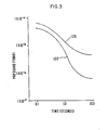
- the present invention is based upon the observation that the time dependence of the pressure reduction for a cyclic processing environment has a first component which is exponential in time and depends on system properties independent of the processing steps.
- a second component depends upon the character of the workpiece which due to its importation from atmosphere brings with it a substantial H 2 0 outgassing.
- the time dependence may be stated as where ,
- the remaining terms express the time dependence in removal of H 2 0 from the residual gasses.
- the different time dependences originate in the surface effects with respect to water vapor for the workpiece including any polymer coatings thereon, or other polymers present (o-rings, etc.).
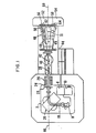
- FIG. 1 illustrates a typical ion implantation system.
- a high voltage terminal 2 is maintained at a selectable potential of +10 kev to +200 kev, typically, with respect to ground.
- an ion source 8 and associated power supplies 10 providing extraction, probe and focusing potentials which need not be considered in detail for the present purposes.
- the ion source operates on a gaseous feed stock requiring gas handling system 6 which may be employed to select among several gas cylinders and to supply the selected gas to the ion source through a controlled leak.
- a high current ion beam 18 diverging from the ion source 8 is momentum analyzed in analyzer magnet 20 and issues from the magnet defined by aperture 22 and further limited by variable slit system 24.
- the beam is then accelerated to ground potential in accelerating tube 26.
- Optical elements 28 such as a quadrupole doublet, operate on the beam to yield a spatial momentum focus at the target planes 56 or 58.
- the typical system of FIG. 1 utilizes an electrostatic deflection system including y deflection plates 40 and x deflection plates 42 to direct the beam 18 over the selected target plane.
- the wave forms are developed in scan system 44 for application to the plates 40 and 42 to achieve a desired scanning pattern.
- a dual channel target chamber 46 is provided to house the workpiece(s) subject to processing.
- An automatic wafer handling system including feed channels 52 and 54 service the two processing channels for introducing semiconductor wafers, one at a time through each of two vacuum locks for time-staggered introduction into the target chamber.
- the wafer handling system properly locates, aligns, cools the wafer during processing and removes the processed wafer from the chamber at the conclusion of processing.
- the wafer handling system is described in copending European application EP-A-0095368 based on U.S. Serial No. 381,085.
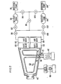
- the target chamber 46 comprises a generally trapezoidal section in the plane of the deflected beam to accommodate either of two alternative trajectories terminating at two respective end stations 62 and 64.
- Beam deflection apparatus not shown, is housed upstream of the target chamber 46 as indicated in FIG. 1 and is understood to impose a desired central trajectory on the ion beam.
- a conventional high vacuum pumping port preferably located on the floor of the chamber, communicates with a high vacuum pump 66.
- a 15 cm cryopump, Model VK12A has been used to obtain a baseline pressure of 53.2 x 10- 6 Pa (4 x 10- 7 Torr) under production cycle conditions.
- the cryopanel 68 is disposed parallel to the top surface of the chamber, and mechanical mounting is secured in straightforward fashion through mechanical insulating standoff 70 to maintain electrical isolation of the cryo-panel from the chamber.
- the cryo-panel is typically constructed of 3 mm gauge stainless steel to which there is brazed a refrigerant circulation channel 72, preferably formed from stainless steel tubing of 6 mm i.d.
- the surface of the panel is then electropolished and the refrigerant channel 72 is terminated in electrically isolated couplings 74 and 76 which in turn communicate through vacuum feedthroughs 78, 80 to a refrigeration system 82. Satisfactory results have been obtained in the present system using a Polycold PCT-200 0 refrigeration system available from Polycold, Inc., San Rafael, California.
- This refrigeration system circulates refrigerant in channel 72 to maintain the cryo-panel in the range -125°C to -150°C.
- the physical size of the target chamber permits a large area cryo-panel. In one system the area of the cryo-panel occupies 0.2 square metres, e.g., 0.4 square metres total surface area.
- the cryo-panel 68 achieves a pumping speed in excess of 10,000 liters per second and is believed to reach pumping speeds as high as 20,000 liters per second for water vapor introduced into the chamber with the wafers.
- cryo-panel Electrical isolation of the cryo-panel permits a partial charge collection function to be served.
- the charge collection is independently derived from the wafer platen under ion bombardment and from other charge collection surfaces disposed within chamber 46.
- the collected charge for the several electrically isolated surfaces is then summed for a measure of the total beam current into the chamber.
- a two-stage roughing cycle is employed for efficient pumpdown according to the scheme briefly described below.
- the wafer is secured to the platen at a given end station, for example 62, and after an interval of 0.2 seconds, valves 90 and 92 are opened to the first stage pumping of the roughing cycle.
- Actuation of all valves in the process cycle is under control of a synchronization interlock logic system which monitors pressure conditions and other variables of the system. Such logic systems are well known and need not be discussed in detail.
- Valves 94 and 96 remain closed with the result that the end station is evacuated by roughing pump 98 through expansion tank 99. Approximately 1/10 second is employed for thjs first stage pumping.
- the first stage is then valved off by valve controllers operating to close valve 92; after approximately 0.2 seconds, the second stage roughing pump and expansion tank is placed in open communication with the end station by opening valve 102.
- the latter pump reduces the pressure to approximately 26.6 Pa (200 microns of Hg) within an interval of approximately 0.3 seconds; after 0.2 seconds, the roughing valve 90 and the second stage valve 102 have been closed and the high vacuum valve 110 opens to expose the wafer at end station 62 to the processing chamber 46.
- the expansion tanks 99 and 109 are continuously evacuated by the respective pumps 98 and 108 to augment the pumping efficiency within the constraints of a fixed duty cycle. This augmenting of the pumping efficiency is discussed in greater detail in copending European application EP-A-0095369 based on U.S.
- Valves 94, 104 and 106 allow evacuation of inter-valve regions, e.g., valves 92-94 in straightforward fashion. Further vacuum plumbing, which need not be discussed, permits the roughing pumps to be applied to other requirements outside the processing cycle.
Landscapes
- Chemical & Material Sciences (AREA)
- Analytical Chemistry (AREA)
- Physical Vapour Deposition (AREA)
Claims (5)
Applications Claiming Priority (2)
| Application Number | Priority Date | Filing Date | Title |
|---|---|---|---|
| US38128882A | 1982-05-24 | 1982-05-24 | |
| US381288 | 1982-05-24 |
Publications (3)
| Publication Number | Publication Date |
|---|---|
| EP0095367A2 EP0095367A2 (de) | 1983-11-30 |
| EP0095367A3 EP0095367A3 (en) | 1985-12-04 |
| EP0095367B1 true EP0095367B1 (de) | 1989-01-04 |
Family
ID=23504456
Family Applications (1)
| Application Number | Title | Priority Date | Filing Date |
|---|---|---|---|
| EP19830302950 Expired EP0095367B1 (de) | 1982-05-24 | 1983-05-23 | Schnelles Evakuieren für Hochvakuumbearbeitung |
Country Status (3)
| Country | Link |
|---|---|
| EP (1) | EP0095367B1 (de) |
| JP (1) | JPS58210161A (de) |
| DE (1) | DE3378868D1 (de) |
Families Citing this family (4)
| Publication number | Priority date | Publication date | Assignee | Title |
|---|---|---|---|---|
| JPH0668962B2 (ja) * | 1987-12-21 | 1994-08-31 | 株式会社東芝 | 真空装置及びそれを用いてプロセスを行う方法 |
| JPH0830260B2 (ja) * | 1990-08-22 | 1996-03-27 | アネルバ株式会社 | 真空処理装置 |
| JP5289721B2 (ja) * | 2007-04-10 | 2013-09-11 | 株式会社Sen | イオン注入装置 |
| CN107993931B (zh) * | 2017-11-30 | 2019-11-19 | 上海华力微电子有限公司 | 提高注入机生产效率的方法 |
Family Cites Families (2)
| Publication number | Priority date | Publication date | Assignee | Title |
|---|---|---|---|---|
| NL6502897A (de) * | 1965-03-06 | 1966-09-07 | ||
| FR2330140A1 (fr) * | 1975-10-31 | 1977-05-27 | Physimeca | Installation comportant une enceinte pour l'execution de certains travaux sous vide pousse |
-
1983
- 1983-05-17 JP JP8517483A patent/JPS58210161A/ja active Granted
- 1983-05-23 EP EP19830302950 patent/EP0095367B1/de not_active Expired
- 1983-05-23 DE DE8383302950T patent/DE3378868D1/de not_active Expired
Also Published As
| Publication number | Publication date |
|---|---|
| EP0095367A3 (en) | 1985-12-04 |
| DE3378868D1 (en) | 1989-02-09 |
| JPS58210161A (ja) | 1983-12-07 |
| EP0095367A2 (de) | 1983-11-30 |
| JPH0332630B2 (de) | 1991-05-14 |
Similar Documents
| Publication | Publication Date | Title |
|---|---|---|
| US5343047A (en) | Ion implantation system | |
| EP0945892B1 (de) | Vorrichtung und Verfahren zur Reinigung einer Ionenquelle während eines Prozesses | |
| US6716727B2 (en) | Methods and apparatus for plasma doping and ion implantation in an integrated processing system | |
| US4371412A (en) | Dry etching apparatus | |
| US5136171A (en) | Charge neutralization apparatus for ion implantation system | |
| US6217715B1 (en) | Coating of vacuum chambers to reduce pump down time and base pressure | |
| EP0283519A1 (de) | Ionenerzeugende apparatur, dünnschichtbildende vorrichtung unter verwendung der ionenerzeugenden apparatur und ionenquelle | |
| EP0532046A1 (de) | Atmospherdruckionisation-Massenspektrometer und Vakuumanlage dafür | |
| US4496843A (en) | Method for producing metal ions | |
| EP0095369B1 (de) | Methoden und Geräte zur Evakuierung einer Schleuse | |
| US6180954B1 (en) | Dual-walled exhaust tubing for vacuum pump | |
| US5413663A (en) | Plasma processing apparatus | |
| US5672882A (en) | Ion implantation device with a closed-loop process chamber pressure control system | |
| EP0095367B1 (de) | Schnelles Evakuieren für Hochvakuumbearbeitung | |
| US4475045A (en) | Rapid pumpdown for high vacuum processing | |
| EP1095217A1 (de) | Vakuumpumpe für plasma | |
| JP4443925B2 (ja) | 陽極パルシングによりプラズマドーピングするための方法及び装置 | |
| US6559601B1 (en) | Plasma vacuum pump | |
| Matsumoto et al. | Development and properties of a Freeman-type hybrid ion source | |
| EP0487656B1 (de) | Gerät zur aufladungsneutralisierung in einem ionenimplantierungssystem | |
| JP2929149B2 (ja) | プラズマ装置 | |
| JP2929151B2 (ja) | プラズマ装置 | |
| JP3235113B2 (ja) | イオン注入装置 | |
| JP3106327B2 (ja) | 電子ビーム励起プラズマ処理装置 | |
| Klöppel et al. | A plasma ion source with plane beam profile for UHV-SIMS measurements |
Legal Events
| Date | Code | Title | Description |
|---|---|---|---|
| PUAI | Public reference made under article 153(3) epc to a published international application that has entered the european phase |
Free format text: ORIGINAL CODE: 0009012 |
|
| AK | Designated contracting states |
Designated state(s): CH DE FR GB LI NL |
|
| 17P | Request for examination filed |
Effective date: 19840508 |
|
| PUAL | Search report despatched |
Free format text: ORIGINAL CODE: 0009013 |
|
| AK | Designated contracting states |
Designated state(s): CH DE FR GB LI NL |
|
| 17Q | First examination report despatched |
Effective date: 19870605 |
|
| 17Q | First examination report despatched |
Effective date: 19870930 |
|
| GRAA | (expected) grant |
Free format text: ORIGINAL CODE: 0009210 |
|
| AK | Designated contracting states |
Kind code of ref document: B1 Designated state(s): CH DE FR GB LI NL |
|
| REF | Corresponds to: |
Ref document number: 3378868 Country of ref document: DE Date of ref document: 19890209 |
|
| ET | Fr: translation filed | ||
| PLBE | No opposition filed within time limit |
Free format text: ORIGINAL CODE: 0009261 |
|
| STAA | Information on the status of an ep patent application or granted ep patent |
Free format text: STATUS: NO OPPOSITION FILED WITHIN TIME LIMIT |
|
| 26N | No opposition filed | ||
| PGFP | Annual fee paid to national office [announced via postgrant information from national office to epo] |
Ref country code: FR Payment date: 19960415 Year of fee payment: 14 |
|
| PGFP | Annual fee paid to national office [announced via postgrant information from national office to epo] |
Ref country code: NL Payment date: 19960417 Year of fee payment: 14 |
|
| PGFP | Annual fee paid to national office [announced via postgrant information from national office to epo] |
Ref country code: DE Payment date: 19960423 Year of fee payment: 14 |
|
| PGFP | Annual fee paid to national office [announced via postgrant information from national office to epo] |
Ref country code: GB Payment date: 19960425 Year of fee payment: 14 |
|
| PGFP | Annual fee paid to national office [announced via postgrant information from national office to epo] |
Ref country code: CH Payment date: 19960429 Year of fee payment: 14 |
|
| PG25 | Lapsed in a contracting state [announced via postgrant information from national office to epo] |
Ref country code: GB Effective date: 19970523 |
|
| PG25 | Lapsed in a contracting state [announced via postgrant information from national office to epo] |
Ref country code: LI Free format text: LAPSE BECAUSE OF NON-PAYMENT OF DUE FEES Effective date: 19970531 Ref country code: CH Free format text: LAPSE BECAUSE OF NON-PAYMENT OF DUE FEES Effective date: 19970531 |
|
| PG25 | Lapsed in a contracting state [announced via postgrant information from national office to epo] |
Ref country code: NL Effective date: 19971201 |
|
| GBPC | Gb: european patent ceased through non-payment of renewal fee |
Effective date: 19970523 |
|
| REG | Reference to a national code |
Ref country code: CH Ref legal event code: PL |
|
| PG25 | Lapsed in a contracting state [announced via postgrant information from national office to epo] |
Ref country code: FR Free format text: LAPSE BECAUSE OF NON-PAYMENT OF DUE FEES Effective date: 19980130 |
|
| NLV4 | Nl: lapsed or anulled due to non-payment of the annual fee |
Effective date: 19971201 |
|
| PG25 | Lapsed in a contracting state [announced via postgrant information from national office to epo] |
Ref country code: DE Free format text: LAPSE BECAUSE OF NON-PAYMENT OF DUE FEES Effective date: 19980203 |
|
| REG | Reference to a national code |
Ref country code: FR Ref legal event code: ST |