EP0094477A1 - Laser system with interchangeable plasma chambers - Google Patents
Laser system with interchangeable plasma chambers Download PDFInfo
- Publication number
- EP0094477A1 EP0094477A1 EP83101553A EP83101553A EP0094477A1 EP 0094477 A1 EP0094477 A1 EP 0094477A1 EP 83101553 A EP83101553 A EP 83101553A EP 83101553 A EP83101553 A EP 83101553A EP 0094477 A1 EP0094477 A1 EP 0094477A1
- Authority
- EP
- European Patent Office
- Prior art keywords
- base
- plasma chamber
- laser system
- respect
- optical
- Prior art date
- Legal status (The legal status is an assumption and is not a legal conclusion. Google has not performed a legal analysis and makes no representation as to the accuracy of the status listed.)
- Granted
Links
Images

Classifications
-
- H—ELECTRICITY
- H01—ELECTRIC ELEMENTS
- H01S—DEVICES USING THE PROCESS OF LIGHT AMPLIFICATION BY STIMULATED EMISSION OF RADIATION [LASER] TO AMPLIFY OR GENERATE LIGHT; DEVICES USING STIMULATED EMISSION OF ELECTROMAGNETIC RADIATION IN WAVE RANGES OTHER THAN OPTICAL
- H01S3/00—Lasers, i.e. devices using stimulated emission of electromagnetic radiation in the infrared, visible or ultraviolet wave range
- H01S3/05—Construction or shape of optical resonators; Accommodation of active medium therein; Shape of active medium
- H01S3/06—Construction or shape of active medium
- H01S3/07—Construction or shape of active medium consisting of a plurality of parts, e.g. segments
- H01S3/073—Gas lasers comprising separate discharge sections in one cavity, e.g. hybrid lasers
-
- H—ELECTRICITY
- H01—ELECTRIC ELEMENTS
- H01S—DEVICES USING THE PROCESS OF LIGHT AMPLIFICATION BY STIMULATED EMISSION OF RADIATION [LASER] TO AMPLIFY OR GENERATE LIGHT; DEVICES USING STIMULATED EMISSION OF ELECTROMAGNETIC RADIATION IN WAVE RANGES OTHER THAN OPTICAL
- H01S3/00—Lasers, i.e. devices using stimulated emission of electromagnetic radiation in the infrared, visible or ultraviolet wave range
- H01S3/02—Constructional details
- H01S3/03—Constructional details of gas laser discharge tubes
Landscapes
- Physics & Mathematics (AREA)
- Electromagnetism (AREA)
- Engineering & Computer Science (AREA)
- Plasma & Fusion (AREA)
- Optics & Photonics (AREA)
- Lasers (AREA)
Abstract
Description
- This invention relates to gas lasers having a sealed plasma chamber using either pure or mixed atomic or molecular gases. More particularly, it relates to such lasers in which the sealed plasma chamber may be replaced by another of the same class by relatively unskilled personnel without a need for optically realigning the system to obtain oscillation.
- In general, gas lasers are constructed with a plasma chamber containing a selected gas or mixture of gases, and 'a set of electrodes that produce a high-intensity current that excites the atoms or molecules to high energy states. A pair of optical mirrors, which may be within or external to the plasma chamber envelope, are provided to produce regeneration, hence causing laser oscillation. The mirrors must be aligned accurately to cause regenreration. The aligned mirrors form the resonator for the gas laser.
- Such gas lasers have been used to obtain laser oscillations in many different configurations using various atomic and molecular gases. The output spectra that are available cover a wide electromagnetic spectrum extending from the far infrared into the visible and near ultraviolet and have power capabilities from a few milliwatts to the megawatt region.
- The practical applications of such lasers have been limited by a number of factors. Many kinds of lasers are effectively limited to laboratory usage because they cannot be operated in a sealed off condition without an auxiliary pumping system that either intermittently or continuously replenishes the gaseous medium. In molecular gas lasers, the composition of the gaseous medium gradually changes under operating conditions caused by molecular disassociation, giving rise to the requirement for the introduction of fresh gases into the envelope as used gases are removed. The life of a laser having a sealed .envelope may also be limited by gaseous reactions or decomposition within the plasma chamber that deteriorate the optical quality of the windows. For the most part, only inert gas lasers, such as Helium-Neon, and Argon, Krypton and other inert gas ion lasers have been practical for operation over an extended period of time as sealed- off units.
- The expense associated with the use of many lasers is a critical factor in commercial applications. For example, there are Helium-Neon lasers which can be manufactured at relatively low cost and which are capable',of operation under sealed conditions for a relatively long period of time. When the plasma chamber in such a laser finally fails, it may be more practical and economical to discard the entire unit rather than to replace the plasma chamber and realign the optical resonator to obtain oscillation.
- In certain higher power and more expensive sealed inert gas lasers, the costs of the plasma chamber and the auxiliary equipment are high. When failure occurs in these more expensive laser systems, the plasma chamber is usually replaced, but that replacement requires skilled personnel because of the high voltages involved and the need for precise optical realignment. Nevertheless, such sealed inert-gas lasers are used commercially because the operating life is sufficiently long to justify the cost of replacement of the plasma chamber.
- That is not true of molecular and most other gas lasers which have a more limited life under sealed operating conditions. For example, in lasers using carbon dioxide, excitation of the plasma causes disassociation of the gas molecules into carbon monoxide and oxygen. Such lasers are provided with a pumping station and the necessary auxiliary equipment to allow operation with a continuous gas flow. Recent developments in the use of catalysts to regenerate the carbon dioxide have lengthened the life of such sealed lasers, but commercial units still require a flow of make-up gas to achieve acceptable operating life.
- Similar and more serious problems arise with gas lasers using halides, for such gases are corrosive and surface reactions reduce the effectiveness of the optical windows. The resulting short life requires that these lasers also be provided with continuing gas replenishment and, in addition, means must be provided for collecting the corrosive used gases.
- The commercial application of many kinds of prior art lasers requiring replenishment of the used gas in the plasma chamber generally require a bulky gas handling system.
- In accordance with the present invention a gas laser is provided in which the plasma chamber can be quickly and easily replaced by relatively unskilled personnel. This feature makes it possible to use sealed plasma chambers in cases where the sealed chamber has a long shelf life, but gradual deterioration occurs when the plasma chamber is operated to obtain oscillations. In many applications such lasers are operated only intermittently. With the elimination of the gas handling system, it becomes posssible to manufacture a compact, and in some important cases, portable and light weight lasers. The invention is addressed to lasers operating at low to medium power output and is not broadly applicable to very high energy lasers.
- The sealed plasma chamber includes the usual high voltage electrodes and optical windows. To make chamber replacement possible without need for elaborate optical realignment, one section of a mating mechanical coupler is secured to the envelope of the demountable plasma chamber and is positioned in a predetermined spatial and angular position with respect to the electrodes, optical windows and the optical axis of the plasma chamber. The positioning of the mechanical coupler with respect to the electrodes, the windows and the optical axis is identical for each of the interchangeable plasma chambers. A separate base on which the resonator mirrors are mounted, and .which may carry the electrical connecting joints to the electrodes, the power supply and auxiliary equipment, is provided with the other section of the mating coupler fixed in a precise predetermined spatial and angular posi- ! tion with respect to a pair of mirrors mounted on the base. The position of this section of the mechanical coupler with respect to the mirrors is identical for each of the interchangeable bases. Each base and each plasma chamber is thus interchangeable with any other similarly aligned unit. When a plasma chamber fails, it is easily replaced by merely disconnecting the old chamber from the base and inserting the replacement. The predetermined positions of the two coupler sections, one with respect to the electrodes and optical axis of the plasma chamber and the other with respect to the two mirrors, precisely locates the replacement chamber in position with sufficient accuracy to produce laser oscillations without elaborate adjustment. In important cases, the sealed plasma chamber containing an optimum laser gas mixture can be manufactured at low cost. This feature makes it possible to discard the used chamber and conveniently replace it with another one. More expensive chambers, such as in molecular lasers using rare isotropic species or those requiring elaborate electrode configuration, can be returned to the factory for reconditioning while the replacement chamber is in service.
- This ability to replace a sealed plasma chamber while retaining the mirrors, power supply and auxiliary equipment, makes it feasible to use lasers in many applications where cost restrictions or conditions of use now rule out their application. Advantage is taken here of the fact that plasma chambers of the types that have a relatively short life under actual operating conditions, may have a satisfactorily long shelf life in an inactive condition. Thus, even these so-called short-lived plasma chambers become feasible for use in many non-laboratory applications.
- The invention also permits different plasma chambers containing different gases but belonging to the same class of lasers to be used with a common base, thus providing greater versatility of application at minimum cost.
- In one embodiment of the invention, the base supports a folded storage capacitor that serves as a Blumlein circuit. The capacitor is formed in two sections positioned in spaced parallel configuration and extending on either side of the plasma chamber. The plasma chamber is in the form of a block of non-conducting impervious material having flat surfaces that are adjacent the inner condenser plates of the capacitor.
- In another embodiment, one mirror is incorporated into the replaceable plasma chamber and a second mirror is positioned on the base.
-
- Figure 1 is an elevation of an interchangeable plasma chamber in accordance with the present invention;
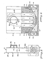
- Figure 2 is a diagrammatic elevation, partly in section along the line A-A of Figure 3, illustrating the plasma chamber in position on its base;
- Figure 3 is a side view of the laser system of Figure 2 with part of the structure cut away to show the plasma chamber construction and partly in section along line B-B of Figure 2 to illustrate the arrangement of a gas switch;
- Figure 4 is a partial view illustrating one method of mirror mount and adjustment; and
- Figure 5 is a partial view similar to Figure 1 illus. trating a plasma chamber incorporating one mirror and one window.
- As illustrated in Figure 1, an interchangeable plasm chamber, generally indicated at 2, includes a sealed en velope 4 formed in a
block 6 of non-conductive imperviou material. In this example, theblock 6 is formed of methacrylate plastic of the kind sold under the trademar Plexiglas. A plasma cavity 8 is formed by a bore extendin transversely through the lower portion of theblock 6. pair ofelectrodes 12 and 14 (see also Figure 3) are posi tioned in the chamber. Theelectrode 12 includes a rec tangular base 16 that is seated in a slot in the block that extends from the exterior wall of theblock 6 int the cavity 8. The outer surface of the base 16 is coir cident with the adjacent surface of theblock 6 and prc vides a contact surface for theelectrode 12. The opposeelectrode 14 is identical in configuration with asimile base 18 that is exposed on the opposite side of thebloc 6. - Two pairs of vertical cooling ducts, generally ind: cated at 22 and 24, formed within the
block 6, open in mechanism. The lower end of aduct 22a is positioned adjacent theelectrodes return duct 22b that also opens into the cavity 8 at a point farther removed from the electrodes. The heated gas flows upwardly through theduct 22a and returns after cooling through theduct 22b. The other pair ofducts duct 24a and returning to the cavity 8 through theduct 24b. - The lower section of the
block 6 is tapered to form a Brewster angle at each end of the cavity 8. Twowindows block 6 and extend over the ends of the .cavity 8. - The plasma chamber is filled with a gas or a mixture of gases suitable for a particular laser. The choice of pressure and the selection of gases, and the selection of materials and Brewster angles for the
windows - The
interchangeable plasma chamber 2 shown in Figure 1 is inserted into abase 32, as shown in Figures 2 and 3. Thebase 32 is in the form of a rectangular tray, formed of heavy aluminum or other rigid material, with upstanding sides that surround the lower portion of theplasma chamber 2. - The base 32 carries a storage capacitor, generally indicated at 34, in the form of a Blumlein printed circuit. A
first section 34a of the capacitor is formed by a printed circuit having twolayers copper layers - A gas switch, generally indicated at 42, is carried by the panel 34b with an outer cup-shaped
electrode shell 44 connected around its perimeter to the rim of an opening of similar size in thecondenser plate 38a. Asecond switch electrode 46 is secured to thecondenser plate 38b and extends into theelectrode shell 44. The composition of the gas within the switch and the details of construction of the switch are well known and are not repeated here. A suitable power supply (not shown) will be connected to thecapacitor 34. - The two
capacitor sections 34a and 34b are supported in spaced face-to-face relationship by the base 32 from which they are suitably insulated. When theplasma chamber 2 is inserted into thebase 32, it slides between thecapacitor sections 34a and 34b with the electode bases 16 and 18 making electrical contact respectively with theinner condenser plates outer condenser plates - the
gas switch 42, which may be' a high-speed pressurized spark gap, may for selected applications be secured to the replaceable plasma chamber with appropriate means for making electrical connections when the plasma chamber is inserted in the base. In another arrangement, the Blumlein capacitors may be affixed to the plasma chamber rather than to the base. The structure is thus flexible in design in that any combination of these components, or any other component of the laser system that may have a short .life, may be selected to be discarded with the used plasma chamber. - The base 32 carries two
mirrors mirror 52 may be positioned between a series of spring supports 56 and a number of adjustingscrews 58 that will permit the mirror to be adjusted to any angle and then locked in that position. Each of the spring supports 56 may be formed of a pair of Belleville washers in opposing face-to-face relationship. Twoopenings end walls base 32. - To insure precise positioning of the
plasma chamber 2 with respect to themirrors base 32, engage prescisely positionedopenings 76 and 78 (Figure 1) that extend upwardly in theblock 6 from twohorizontal shoulders block 6. Thepins plasma chamber 2. In addition, theshoulders electrodes windows base 32, with thepins openings shoulders mirrors - Any desired means may be employed for mounting the plasma chamber on the base, the requirement being for a mechanical coupling having two mating sections, one section affixed to or forming a part of the base and precisely positioned with respect to the mirrors, and the other section affixed to or forming part of the plasma chamber and precisely positioned with respect to the electrodes, the windows and the optical axis of the plasma chamber.
- In manufacture, each interchangeable plasma chamber is fabricated with exactly the same spatial and angular relationship between its section of the mechanical coupling, (which in this case comprises the
openings shoulders 82 and 84) and the electrodes, windows and optical axis. Each interchangeable base is fabricated with exactly the same spatial and angular relation between its section of the mechanical coupling (which in this case comprises thepins pins 72 and 74) and the twomirrors - The precision with which the dimensional accuracy must be controlled depends upon the particular characteristics of the laser being used. In general, accuracies readily attainable in production will be adequate to enable laser oscillations to be produced either without optical adjustment or with only minor adjustment of the mirrors.
- The
plasma chamber 2 may, if desired, be fabricated with one mirror and one window, in which case the base carries only a single mirror. Such an arrangement is illustrated in the partial view of Figure 5. Amirror 86, cemented to a vertical surface of theblock 6 at the end of the cavity 8, replaces themirror 54 on thebase 32. Thewindow 28 is eliminated. Only themirror 52 is carried by thebase 32. The operation is essentially the same as dscribed previously with the obvious adjustment in the mounting relationships of the section of the coupling means on the plasma chamber to include the mirror now mounted on the plasma chamber.
Claims (10)
said envelope comprises
a block of insulating material having opposing flat surfaces.
each of said transmission type capacitors is positioned adjacent one of said flat surfaces of said envelope.
Priority Applications (1)
| Application Number | Priority Date | Filing Date | Title |
|---|---|---|---|
| AT83101553T ATE20510T1 (en) | 1982-02-23 | 1983-02-18 | LASER DEVICE WITH INTERCHANGEABLE PLASMA CHAMBERS. |
Applications Claiming Priority (2)
| Application Number | Priority Date | Filing Date | Title |
|---|---|---|---|
| US35142482A | 1982-02-23 | 1982-02-23 | |
| US351424 | 1982-02-23 |
Publications (2)
| Publication Number | Publication Date |
|---|---|
| EP0094477A1 true EP0094477A1 (en) | 1983-11-23 |
| EP0094477B1 EP0094477B1 (en) | 1986-06-18 |
Family
ID=23380871
Family Applications (1)
| Application Number | Title | Priority Date | Filing Date |
|---|---|---|---|
| EP83101553A Expired EP0094477B1 (en) | 1982-02-23 | 1983-02-18 | Laser system with interchangeable plasma chambers |
Country Status (5)
| Country | Link |
|---|---|
| EP (1) | EP0094477B1 (en) |
| JP (1) | JPS58157185A (en) |
| AT (1) | ATE20510T1 (en) |
| CA (1) | CA1189942A (en) |
| DE (1) | DE3364121D1 (en) |
Cited By (3)
| Publication number | Priority date | Publication date | Assignee | Title |
|---|---|---|---|---|
| GB2235817A (en) * | 1989-08-22 | 1991-03-13 | Marconi Gec Ltd | Dye lasers |
| GB2312985A (en) * | 1996-05-07 | 1997-11-12 | Optomedic Medical Technologies | Gas laser with disposable module |
| WO2002043197A2 (en) * | 2000-11-21 | 2002-05-30 | Zhang Yong F | Portable low-power gas discharge laser |
Citations (3)
| Publication number | Priority date | Publication date | Assignee | Title |
|---|---|---|---|---|
| FR2175662A1 (en) * | 1972-03-17 | 1973-10-26 | Comp Generale Electricite | |
| US3781709A (en) * | 1972-08-02 | 1973-12-25 | Siemens Ag | Laser arrangement |
| US4201951A (en) * | 1978-04-03 | 1980-05-06 | Lexel Corporation | Cascaded plasma tube ion laser having single resonator structure |
-
1983
- 1983-02-18 EP EP83101553A patent/EP0094477B1/en not_active Expired
- 1983-02-18 DE DE8383101553T patent/DE3364121D1/en not_active Expired
- 1983-02-18 AT AT83101553T patent/ATE20510T1/en not_active IP Right Cessation
- 1983-02-23 JP JP58030149A patent/JPS58157185A/en active Granted
- 1983-02-23 CA CA000422188A patent/CA1189942A/en not_active Expired
Patent Citations (3)
| Publication number | Priority date | Publication date | Assignee | Title |
|---|---|---|---|---|
| FR2175662A1 (en) * | 1972-03-17 | 1973-10-26 | Comp Generale Electricite | |
| US3781709A (en) * | 1972-08-02 | 1973-12-25 | Siemens Ag | Laser arrangement |
| US4201951A (en) * | 1978-04-03 | 1980-05-06 | Lexel Corporation | Cascaded plasma tube ion laser having single resonator structure |
Cited By (5)
| Publication number | Priority date | Publication date | Assignee | Title |
|---|---|---|---|---|
| GB2235817A (en) * | 1989-08-22 | 1991-03-13 | Marconi Gec Ltd | Dye lasers |
| GB2235817B (en) * | 1989-08-22 | 1993-10-27 | Marconi Gec Ltd | Lasers |
| GB2312985A (en) * | 1996-05-07 | 1997-11-12 | Optomedic Medical Technologies | Gas laser with disposable module |
| WO2002043197A2 (en) * | 2000-11-21 | 2002-05-30 | Zhang Yong F | Portable low-power gas discharge laser |
| WO2002043197A3 (en) * | 2000-11-21 | 2003-06-12 | Yong F Zhang | Portable low-power gas discharge laser |
Also Published As
| Publication number | Publication date |
|---|---|
| EP0094477B1 (en) | 1986-06-18 |
| JPS58157185A (en) | 1983-09-19 |
| ATE20510T1 (en) | 1986-07-15 |
| JPH0348673B2 (en) | 1991-07-25 |
| CA1189942A (en) | 1985-07-02 |
| DE3364121D1 (en) | 1986-07-24 |
Similar Documents
| Publication | Publication Date | Title |
|---|---|---|
| US4774714A (en) | Laser system with interchangeable modules and method for interchanging such modules | |
| US5661746A (en) | Free-space gas slab laser | |
| US5418809A (en) | Modular slab assembly for a face-pumped laser | |
| US5828686A (en) | Cartridge excimer laser system | |
| US3815047A (en) | Transversely-excited waveguide gas laser | |
| US6198758B1 (en) | Laser with heat transfer system and method | |
| US6198759B1 (en) | Laser system and method for beam enhancement | |
| EP0096899A2 (en) | Pulsed gas laser in a sealed structure | |
| US8942270B2 (en) | Diffusion-cooled CO2 laser with flexible housing | |
| US20020061045A1 (en) | Portable low-power gas discharge laser | |
| US4481634A (en) | RF Excited metal waveguide laser | |
| US6195379B1 (en) | Laser assembly system and method | |
| CA1224557A (en) | Laser system with interchangeable modules and method for interchanging such modules | |
| EP0094477B1 (en) | Laser system with interchangeable plasma chambers | |
| US4703489A (en) | Waveguide laser | |
| US6963596B2 (en) | Pre-ionizer for RF-energized gas laser | |
| US9614342B2 (en) | Air-cooled carbon-dioxide laser | |
| US5854806A (en) | Multi-channel, RF-excited gas discharge laser | |
| GB2098791A (en) | Sealed-off CO2 laser | |
| US4771437A (en) | Integrated laser/FLIR rangefinder | |
| US5684821A (en) | Microwave excited laser with uniform gas discharge | |
| JP2005044808A (en) | Drift tube accelerator for ion packet acceleration | |
| US6442185B1 (en) | All-metal, DC excited laser with RF pre-ionization | |
| JPH047111B2 (en) | ||
| JPS63228682A (en) | Gas laser oscillator |
Legal Events
| Date | Code | Title | Description |
|---|---|---|---|
| PUAI | Public reference made under article 153(3) epc to a published international application that has entered the european phase |
Free format text: ORIGINAL CODE: 0009012 |
|
| AK | Designated contracting states |
Designated state(s): AT BE CH DE FR GB IT LI LU NL SE |
|
| 17P | Request for examination filed |
Effective date: 19840229 |
|
| GRAA | (expected) grant |
Free format text: ORIGINAL CODE: 0009210 |
|
| AK | Designated contracting states |
Kind code of ref document: B1 Designated state(s): AT BE CH DE FR GB IT LI LU NL SE |
|
| PG25 | Lapsed in a contracting state [announced via postgrant information from national office to epo] |
Ref country code: NL Effective date: 19860618 Ref country code: IT Free format text: LAPSE BECAUSE OF FAILURE TO SUBMIT A TRANSLATION OF THE DESCRIPTION OR TO PAY THE FEE WITHIN THE PRESCRIBED TIME-LIMIT;WARNING: LAPSES OF ITALIAN PATENTS WITH EFFECTIVE DATE BEFORE 2007 MAY HAVE OCCURRED AT ANY TIME BEFORE 2007. THE CORRECT EFFECTIVE DATE MAY BE DIFFERENT FROM THE ONE RECORDED. Effective date: 19860618 Ref country code: FR Free format text: THE PATENT HAS BEEN ANNULLED BY A DECISION OF A NATIONAL AUTHORITY Effective date: 19860618 Ref country code: BE Effective date: 19860618 Ref country code: AT Effective date: 19860618 |
|
| REF | Corresponds to: |
Ref document number: 20510 Country of ref document: AT Date of ref document: 19860715 Kind code of ref document: T |
|
| PG25 | Lapsed in a contracting state [announced via postgrant information from national office to epo] |
Ref country code: SE Effective date: 19860630 |
|
| REF | Corresponds to: |
Ref document number: 3364121 Country of ref document: DE Date of ref document: 19860724 |
|
| EN | Fr: translation not filed | ||
| NLV1 | Nl: lapsed or annulled due to failure to fulfill the requirements of art. 29p and 29m of the patents act | ||
| PG25 | Lapsed in a contracting state [announced via postgrant information from national office to epo] |
Ref country code: LU Free format text: LAPSE BECAUSE OF NON-PAYMENT OF DUE FEES Effective date: 19870228 |
|
| PLBE | No opposition filed within time limit |
Free format text: ORIGINAL CODE: 0009261 |
|
| STAA | Information on the status of an ep patent application or granted ep patent |
Free format text: STATUS: NO OPPOSITION FILED WITHIN TIME LIMIT |
|
| 26N | No opposition filed | ||
| PG25 | Lapsed in a contracting state [announced via postgrant information from national office to epo] |
Ref country code: GB Effective date: 19890218 |
|
| PG25 | Lapsed in a contracting state [announced via postgrant information from national office to epo] |
Ref country code: LI Effective date: 19890228 Ref country code: CH Effective date: 19890228 |
|
| GBPC | Gb: european patent ceased through non-payment of renewal fee | ||
| REG | Reference to a national code |
Ref country code: CH Ref legal event code: PL |
|
| PG25 | Lapsed in a contracting state [announced via postgrant information from national office to epo] |
Ref country code: DE Effective date: 19891101 |