EP0094446A1 - Pressure detector with a membrane and an overload stopper - Google Patents
Pressure detector with a membrane and an overload stopper Download PDFInfo
- Publication number
- EP0094446A1 EP0094446A1 EP19820104379 EP82104379A EP0094446A1 EP 0094446 A1 EP0094446 A1 EP 0094446A1 EP 19820104379 EP19820104379 EP 19820104379 EP 82104379 A EP82104379 A EP 82104379A EP 0094446 A1 EP0094446 A1 EP 0094446A1
- Authority
- EP
- European Patent Office
- Prior art keywords
- pressure
- membrane
- stop
- overload
- stop screw
- Prior art date
- Legal status (The legal status is an assumption and is not a legal conclusion. Google has not performed a legal analysis and makes no representation as to the accuracy of the status listed.)
- Granted
Links
- 239000012528 membrane Substances 0.000 title claims abstract description 37
- 230000006835 compression Effects 0.000 abstract description 3
- 238000007906 compression Methods 0.000 abstract description 3
- 238000005259 measurement Methods 0.000 description 4
- 238000010276 construction Methods 0.000 description 2
- 238000013461 design Methods 0.000 description 2
- 230000007423 decrease Effects 0.000 description 1
- 230000006735 deficit Effects 0.000 description 1
- 238000011161 development Methods 0.000 description 1
- 230000000694 effects Effects 0.000 description 1
- 238000011156 evaluation Methods 0.000 description 1
- 230000001771 impaired effect Effects 0.000 description 1
- 230000002093 peripheral effect Effects 0.000 description 1
- 230000035945 sensitivity Effects 0.000 description 1
- 230000003746 surface roughness Effects 0.000 description 1
- 230000001960 triggered effect Effects 0.000 description 1
Images
Classifications
-
- G—PHYSICS
- G01—MEASURING; TESTING
- G01L—MEASURING FORCE, STRESS, TORQUE, WORK, MECHANICAL POWER, MECHANICAL EFFICIENCY, OR FLUID PRESSURE
- G01L19/00—Details of, or accessories for, apparatus for measuring steady or quasi-steady pressure of a fluent medium insofar as such details or accessories are not special to particular types of pressure gauges
- G01L19/06—Means for preventing overload or deleterious influence of the measured medium on the measuring device or vice versa
- G01L19/0618—Overload protection
-
- G—PHYSICS
- G01—MEASURING; TESTING
- G01L—MEASURING FORCE, STRESS, TORQUE, WORK, MECHANICAL POWER, MECHANICAL EFFICIENCY, OR FLUID PRESSURE
- G01L9/00—Measuring steady of quasi-steady pressure of fluid or fluent solid material by electric or magnetic pressure-sensitive elements; Transmitting or indicating the displacement of mechanical pressure-sensitive elements, used to measure the steady or quasi-steady pressure of a fluid or fluent solid material, by electric or magnetic means
- G01L9/0041—Transmitting or indicating the displacement of flexible diaphragms
- G01L9/0051—Transmitting or indicating the displacement of flexible diaphragms using variations in ohmic resistance
Definitions
- the invention relates to a pressure transducer with a diaphragm which is acted upon on one side by the pressure to be taken up and clamped on a transducer housing and which is equipped on its pressure-facing side with strain gauges, with an overload stop arranged on the pressure-facing side of the diaphragm.
- the permissible overload range of conventional pressure transducers for measuring hydraulic pressures is generally around twice the measuring range end pressure. If a higher pressure occurs, plastic deformation or even breakage of the membrane serving as the measuring element can occur.
- pressure peaks often occur that are several times the operating pressure to be measured. Such pressure peaks are triggered in particular when switching solenoid valves.
- Pressure transducers whose overload range is at double the measuring range end pressure, which in turn is designed to achieve the highest possible measuring accuracy according to the operating pressure to be expected, are in many cases damaged by the high pressure peaks that occur.
- the nominal pressure i.e. the measuring range end pressure
- the accuracy of a measurement decreases all the more, the smaller the ratio of the measured variable to the measuring range end pressure of the measuring device, so that a lower measuring accuracy must be accepted in these cases.
- the membrane In a known pressure transducer of the type mentioned at the outset, the membrane is designed in the form of a ring; it is connected to a rigid middle section that comes into contact with the overload stop when overloaded. Since the strain gauges are only attached to the circular membrane, but not on the rigid middle part, there are no difficulties in contact with the overload stop; at very high pressures, for example above 100 bar, as they often occur in hydraulic systems, a relatively large membrane diameter is required to achieve the desired measurement accuracy (DE-OS 26 11 494).
- the object of the invention is therefore to design a pressure transducer of the type mentioned in the introduction in such a way that, with a high overload capacity, a high level of measurement sensitivity is achieved without increasing the membrane diameter.
- the membrane is a circular plate also equipped in its middle part with strain gauges, and in that the overload stop is a stop screw guided without play in an internal thread of the transducer housing, the end face of which faces the middle part of the membrane is provided with an electrical insulating layer.
- the stop screw can be adjusted so that the membrane contacts the end face of the stop screw at a predetermined pressure above the measuring range end pressure. If the pressure exceeds this predetermined value, the membrane is supported on the end face of the stop screw. The greater the pressure, the greater the contact area between the membrane and the end face of the stop screw, so that the overload protection effect increases with increasing pressure. As a result, the stress on the membrane increases only slightly with increasing pressure.
- the electrically insulating layer arranged on the end face of the stop screw prevents the strain gauges arranged in the central part of the membrane from being impaired or damaged by metallic contact with the stop screw.
- the relatively thin insulating layer does not affect the rigidity and load-bearing capacity of the overload stop, but it prevents contact between the strain gauges and the metallic surface of the stop screw.
- the stop screw is expediently guided axially without play by a compression spring supported on the transducer housing in the internal thread. The flanks of the thread of the stop screw are pressed against the flank side of the internal thread from which the operating load in the event of an overload must also be absorbed. As a result, the possible thread play does not affect the setting accuracy of the overload stop.
- the internal thread receiving the stop screw is arranged in a traverse of the transducer housing.
- a membrane 2 which acts as a measuring element and has the shape of a circular plate, is attached to the end face of an approximately hollow cylindrical sensor housing 1.
- a peripheral edge 3 projecting upward from the edges of the membrane 2 is attached to the sensor housing 1 by means of a soldered or welded connection 4.
- the sensor housing 1 registers on its outside External thread 5, by means of which it can be screwed into a specific bore (not shown) of a hydraulic system or the like.
- the pressure to be measured is then on the outside of the membrane 2.
- a strain gauge rosette consisting of strain gauges 6, 7 is attached to the pressure-facing inside of the membrane 2, from whose connection contacts 8 electrical lines 9 lead to the (not shown) evaluation circuit of the measuring device.
- the device is used to measure hydraulic pressures.
- a cross member 11 which is made in one piece therewith and has bores 12 for the lines 9.
- a bore with an internal thread 13, which receives a stop screw 14, is arranged centrally in the cross member 11.
- the end face 15 of the stop screw 14 is provided with an electrical insulating layer 16 and, in the idle state, lies at a predetermined distance on the side of the diaphragm 2 which is turned away from pressure. This distance can be set by turning the stop screw 14.
- a compression spring 17 arranged between the cross member 11 and the head of the stop screw 14 guides the stop screw 14 in the internal thread 13 without play.
- the membrane 2 When the pressure to be measured is applied to the outside of the membrane 2, the membrane 2 bulges inwards. The change in length of the strain gauges 6, 7 that occurs is converted into an electrical measurement signal. If the pressure on the outside of the membrane exceeds a predetermined value which lies above the nominal pressure of the pressure transducer, the membrane 2 is supported on the end face 15 of the stop unscrew 14. This leads to a contact between the strain gauges 7 and the insulating layer 16, whereby damage or other impairment of the strain gauges 7 is prevented. The pressure at which the membrane 2 is supported on the stop screw 14 can be precisely adjusted by turning the stop screw 14.
- the surface roughness of the end face 15 of the stop screw 14 is chosen to be as small as possible in order to achieve sufficient functional reliability of the overload stop even with a very thin insulating layer 16.
Abstract
Description
Die Erfindung betrifft einen Druckaufnehmer mit einer auf einr Seite von dem aufzunehmenden Druck beaufschlagbaren, an einem Aufnehmergehäuse eingespannten Membran, die auf ihrer druckabgekehrten Seite mit Dehnungsmeßstreifen bestückt ist, mit einem auf der druckabgekehrten Seite der Membran angeordneten Überlastanschlag.The invention relates to a pressure transducer with a diaphragm which is acted upon on one side by the pressure to be taken up and clamped on a transducer housing and which is equipped on its pressure-facing side with strain gauges, with an overload stop arranged on the pressure-facing side of the diaphragm.
Der zulässige Überlastbereich herkömmlicher Druckaufnehmer zur Messung hydraulischer Drücke liegt im allgemeinen etwa beim doppelten Meßbereichsenddruck. Wenn ein höherer Druck auftritt, kann es zu einer plastischen Verformung oder schließlich sogar zu einem Bruch der als Meßglied dienenden Membran kommen.The permissible overload range of conventional pressure transducers for measuring hydraulic pressures is generally around twice the measuring range end pressure. If a higher pressure occurs, plastic deformation or even breakage of the membrane serving as the measuring element can occur.
In hydraulischen Anlagen treten häufig Druckspitzen auf, die ein Mehrfaches des zu messenden Betriebsdrucks betragen. Derartige Druckspitzen werden insbesondere bei Schaltvorgängen von Magnetventilen ausgelöst. Druckaufnehmer, deren Überlastbereich beim doppelten Meßbereichsenddruck liegt, der wiederum zur Erzielung einer möglichst hohen Meßgenauigkeit nach dem zu erwartenden Betriebsdruck ausgelegt ist, werden in vielen Fällen durch die auftretenden hohen Druckspitzen beschädigt. Um eine solche Beschädigung des Druckaufnehmers zu verhindern, muß der Nenndruck, d.h. der Meßbereichsenddruck, ein Mehrfaches des zu messenden Betriebsdrucks betragen. Die Genauigkeit einer Messung nimmt jedoch umso stärker ab, je kleiner das Verhältnis der Meßgröße zum Meßbereichsenddruck des Meßgerätes ist, so daß in diesen Fällen eine geringere Meßgenauigkeit in Kauf genommen werden muß.In hydraulic systems, pressure peaks often occur that are several times the operating pressure to be measured. Such pressure peaks are triggered in particular when switching solenoid valves. Pressure transducers whose overload range is at double the measuring range end pressure, which in turn is designed to achieve the highest possible measuring accuracy according to the operating pressure to be expected, are in many cases damaged by the high pressure peaks that occur. To prevent such damage to the pressure transducer, the nominal pressure, i.e. the measuring range end pressure, a multiple of the operating pressure to be measured. However, the accuracy of a measurement decreases all the more, the smaller the ratio of the measured variable to the measuring range end pressure of the measuring device, so that a lower measuring accuracy must be accepted in these cases.
Um eine Erhöhung des Überlastbereichs zu erreichen, ist es bekannt, den mittleren Teil der Membran bei Überlast an einem ringförmigen Überlastanschlag abzustützen. Die Dehnungsmeßstreifen sind jedoch nicht an der Membran, sondern an einem gesonderten Meßglied angebracht. Die Bewegung der Membran wird durch einen zentrischen Stift auf das Meßglied übertragen. Dies bedingt einen verhältnismäßig hohen Bauaufwand (US-PS 3o 22 672).In order to increase the overload range, it is known to apply the middle part of the membrane in the event of overload to support an annular overload stop. However, the strain gauges are not attached to the membrane, but to a separate measuring element. The movement of the membrane is transmitted to the measuring element by a central pin. This requires a relatively high construction cost (US-PS 3o 22 672).
Bekannt ist auch, auf der druckabgekehrten Seite der Membran über ihre gesamte frei zugängliche Fläche ein sogenanntes Membranbett anzuordnen, an das sich die Membran bei Überlastung flächig anlegt (DE-OS 2o 52 515). Ein solcher Überlastanschlag ist jedoch nicht brauchbar, wenn die Dehnungsmeßstreifen unmittelbar auf der Membran, und zwar auf deren druckabgekehrten Seite angebracht werden. Ein Überlastanschlag in Form eines Membranbetts kann daher nur bei Dehnungsmeßstreifen-Druckaufnehmern von verhältnismäßig aufwendigem Aufbau verwendet werden, bei dem ein mit der Membran verbundener Stift die zu messende Kraft auf ein gesondertes Meßglied überträgt. Diese Bauform eignet sich jedoch nur zur Messung von kleinen Drücken. Bei größeren Drücken wird die Beanspruchung der Membran selbst zu groß, so daß der Weg für das nachgeschaltete Meßglied nicht mehr ausreicht, um ein ausreichend großes Signal zu erzeugen.It is also known to arrange a so-called membrane bed over its entire freely accessible surface on the pressure-facing side of the membrane, to which the membrane lies flat when overloaded (DE-OS 2o 52 515). However, such an overload stop is not usable if the strain gauges are attached directly to the diaphragm, namely on its side opposite to the pressure. An overload stop in the form of a membrane bed can therefore only be used in strain gauge pressure transducers of relatively complex construction, in which a pin connected to the membrane transfers the force to be measured to a separate measuring element. However, this design is only suitable for measuring small pressures. At higher pressures, the stress on the membrane itself becomes too great, so that the path for the downstream measuring element is no longer sufficient to generate a sufficiently large signal.
Bei einem bekannten Druckaufnehmer der eingangs genannten Gattung ist die Membran kreisringförmig ausgeführt; sie ist mit einem starren Mittelteil verbunden, das bei Überlastung am Überlastanschlag zur Anlage kommt. Da die Dehnungsmeßstreifen nur auf der kreisringförmigen Membran angebracht sind, nicht jedoch auf dem starren Mittelteil, ergeben sich durch die Berührung mit dem Überlastanschlag zwar keine Schwierigkeiten; bei sehr großen Drücken, beispielsweise über 1oo bar, wie sie häufig in hydraulischen Anlagen auftreten, ist jedoch ein verhältnismäßig großer Membrandurchmesser erforderlich, um die gewünschte Meßgenauigkeit zu erreichen (DE-OS 26 11 494).In a known pressure transducer of the type mentioned at the outset, the membrane is designed in the form of a ring; it is connected to a rigid middle section that comes into contact with the overload stop when overloaded. Since the strain gauges are only attached to the circular membrane, but not on the rigid middle part, there are no difficulties in contact with the overload stop; at very high pressures, for example above 100 bar, as they often occur in hydraulic systems, a relatively large membrane diameter is required to achieve the desired measurement accuracy (DE-OS 26 11 494).
Aufgabe der Erfindung ist es daher, einen Druckaufnehmer der eingangs genannten Gattung so auszubilden, daB bei hoher Überlastbarkeit gleichwohl eine hohe Meßempfindlichkeit ohne Vergrößerung des Membrandurchmessers erreicht wird.The object of the invention is therefore to design a pressure transducer of the type mentioned in the introduction in such a way that, with a high overload capacity, a high level of measurement sensitivity is achieved without increasing the membrane diameter.
Diese Aufgabe wird erfindungsgemäß dadurch gelöst, daB die Membran eine auch in ihrem Mittelteil mit Dehnungsmeßstreifen bestückte Kreisplatte ist, und daB der Überlastanschlag eine in einem Innengewinde des Aufnehmergehäuses spielfrei geführte Anschlagschraube ist, deren dem Mittelteil der Membran zugekehrte Stirnfläche mit einer elektrischen Isolierschicht versehen ist.This object is achieved according to the invention in that the membrane is a circular plate also equipped in its middle part with strain gauges, and in that the overload stop is a stop screw guided without play in an internal thread of the transducer housing, the end face of which faces the middle part of the membrane is provided with an electrical insulating layer.
Die Anschlagschraube kann so eingestellt werden, daß die Membran bei einem vorgegebenen Druck oberhalb des Meßbereichenddrucks die Stirnfläche der Anschlagschraube berührt. Übersteigt der Druck diesen vorgegebenen Wert, so wird die Membran an der Stirnfläche der Anschlagschraube abgestützt. Je größer der Druck wird, umso größer wird die Berührungsfläche zwischen der Membran und der Stirnfläche der Anschlagschraube, so daB sich die Überlast-Schutzwirkung mit zunehmendem Druck erhöht. Dadurch erhöht sich die Beanspruchung der Membran mit zunehmendem Druck nur noch gringfügig.The stop screw can be adjusted so that the membrane contacts the end face of the stop screw at a predetermined pressure above the measuring range end pressure. If the pressure exceeds this predetermined value, the membrane is supported on the end face of the stop screw. The greater the pressure, the greater the contact area between the membrane and the end face of the stop screw, so that the overload protection effect increases with increasing pressure. As a result, the stress on the membrane increases only slightly with increasing pressure.
Die an der Stirnfläche der Anschlagschraube angeordnete, elektrisch isolierende Schicht verhindert eine Beeinträchtigung oder Beschädigung der im Mittelteil der Membran angeordneten Dehnungsmeßstreifen durch eine metallische Berührung mit der Anschlagschraube. Die verhältnismäßig dünne Isolierschicht beeinträchtigt die Steifigkeit und Tragfähigkeit des Überlastanschlags nichts sie verhindert jedoch eine Berührung zwischen den Dehnungsmeßstreifen und der metallischen Oberfläche der Anschlagschraube. Zweckmäßigerweise wird die Anschlagschraube durch eine sich am Aufnehmergehäuse abstützende Druckfeder im Innengewinde axial spielfrei geführt. Die Flanken des Gewindes der Anschlagschraube werden dabei gegen diejenige Flankenseite des Innengewindes gedrückt, von der auch die Betriebsbeanspruchung bei Überlast aufgenommen werden muß. Dadurch beeinträchtigt das mögliche Gewindespiel die Einstellgenauigkeit des Überlastanschlags nicht.The electrically insulating layer arranged on the end face of the stop screw prevents the strain gauges arranged in the central part of the membrane from being impaired or damaged by metallic contact with the stop screw. The relatively thin insulating layer does not affect the rigidity and load-bearing capacity of the overload stop, but it prevents contact between the strain gauges and the metallic surface of the stop screw. The stop screw is expediently guided axially without play by a compression spring supported on the transducer housing in the internal thread. The flanks of the thread of the stop screw are pressed against the flank side of the internal thread from which the operating load in the event of an overload must also be absorbed. As a result, the possible thread play does not affect the setting accuracy of the overload stop.
In Weiterbildung des Erfindungsgedankens ist vorgesehen, daß das die Anschlagschraube aufnehmende Innengewinde in einer Traverse des Aufnehmergehäuses angeordnet ist. Mit sehr einfachen konstruktiven Mitteln wird hierdurch eine sehr tragfähige Abstützung der Anschlagschraube im Aufnehmergehäuse erreicht.In a further development of the inventive concept, it is provided that the internal thread receiving the stop screw is arranged in a traverse of the transducer housing. With very simple structural means, a very stable support of the stop screw in the transducer housing is achieved.
Eine Durchmesservergrößerung gegenüber Ausführungsformen mit starrem Membranmittelteil wird vermieden.An increase in diameter compared to embodiments with a rigid membrane middle part is avoided.
Die Erfindung wird nachfolgend an einem Ausführungsbeispiel näher erläutert, das in der Zeichnung dargestellt ist. Es zeigt:
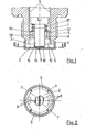
- Fig. 1 einen Längsschnitt durch einen Druckaufnehmer mit einstellbarem Überlastanschlag und
- Fig. 2 einen Schnitt längs der Linie II-II in Fig. 1.
- Fig. 1 shows a longitudinal section through a pressure sensor with adjustable overload stop and
- 2 shows a section along the line II-II in FIG. 1st
An der Stirnfläche eines angenähert hohlzylindrischen Aufnehmergehäuses 1 ist eine als Meßglied wirkende Membran 2 angebracht, die die Form einer Kreisplatte hat. Ein von den Rändern der Membran 2 nach oben ragender, umlaufender Rand 3 ist am Aufnehmergehäuse 1 mittels einer Löt- oder Schweißverbindung 4 angebracht.A
Das Aufnehmergehäuse 1 trägt an seiner Außenseite ein Außengewinde 5, mit dem es in einer hierzu bestimmten (nicht dargestellten) Gewindebohrung einer Hydraulikanlage od. dgl. eingeschraubt werden kann. Der zu messende Druck steht dann auf der Außenseite der Membran 2 an.The sensor housing 1 registers on its outside
An der druckabgekehrten Innenseite der Membran 2 ist eine aus Dehnungsmeßstreifen 6, 7 bestehende Dehnungsmeßstreifen-Rosette angebracht, von deren AnschluBkontakten 8 elektrische Leitungen 9 zur (nicht dargestellten) Auswerteschaltung des Meßgeräts führen. Das Gerät dient zur Messung hydraulischer Drücke.A strain gauge rosette consisting of
In einer Gehäusebohrung 1o des Aufnehmergehäuses 1 ist eine damit einstückig ausgeführte Traverse 11 angeordnet, die Bohrungen 12 für die Leitungen 9 aufweist. Zentrisch in der Traverse 11 ist eine Bohrung mit Innengewinde 13 angeordnet, das eine Anschlagschraube 14 aufnimmt. Die Stirnfläche 15 der Anschlagschraube 14 ist mit einer elektrischen Isolierschicht 16 versehen und liegt im Ruhezustand in einem vorgegebenen Abstand auf der druckabgekehrten Seite der Membran 2. Dieser Abstand ist durch Verdrehen der Anschlagschraube 14 einstellbar.In a housing bore 10 of the transducer housing 1 there is arranged a
Eine zwischen der Traverse 11 und dem Kopf der Anschlagschraube 14 angeordnete Druckfeder 17 führt die Anschlagschraube 14 spielfrei im Innengewinde 13.A
Wenn die Membran 2 an ihrer Außenseite mit dem zu messenden Druck beaufschlagt wird, wölbt sich die Membran 2 nach innen. Die dabei auftretende Längenänderung der Dehnungsmeßstreifen 6, 7 wird in ein elektrisches Meßsignal umgesetzt. Überschreitet der auf der Membranaußenseite anstehende Druck einen vorgegebenen Wert, der oberhalb des Nenndrucks des Druckaufhehmers liegt, so stützt sich die Membran 2 an der Stirnfläche 15 der Anschlagschraube 14 ab. Dabei kommt es zu einer Berührung zwischen den Dehnungsmeßstreifen 7 und der Isolierschicht 16, wodurch eine Beschädigung oder sonstige Beeinträchtigung der Dehnungsmeßstreifen 7 verhindert wird. Der Druck, bei dem sich die Membran 2 an der Anschlagschraube 14 abstützt, kann durch Verdrehen der Anschlagschraube 14 genau eingestellt werden.When the pressure to be measured is applied to the outside of the
Die Oberflächenrauhigkeit der Stirnseite 15 der Anschlagschraube 14 wird möglichst klein gewählt, um auch bei sehr dünner Isolierschicht 16 eine ausreichende Funktionssicherheit des Überlastanschlags zu erreichen.The surface roughness of the
Claims (3)
Priority Applications (2)
| Application Number | Priority Date | Filing Date | Title |
|---|---|---|---|
| DE8282104379T DE3269049D1 (en) | 1982-05-19 | 1982-05-19 | Pressure detector with a membrane and an overload stopper |
| EP19820104379 EP0094446B1 (en) | 1982-05-19 | 1982-05-19 | Pressure detector with a membrane and an overload stopper |
Applications Claiming Priority (1)
| Application Number | Priority Date | Filing Date | Title |
|---|---|---|---|
| EP19820104379 EP0094446B1 (en) | 1982-05-19 | 1982-05-19 | Pressure detector with a membrane and an overload stopper |
Publications (2)
| Publication Number | Publication Date |
|---|---|
| EP0094446A1 true EP0094446A1 (en) | 1983-11-23 |
| EP0094446B1 EP0094446B1 (en) | 1986-02-12 |
Family
ID=8189040
Family Applications (1)
| Application Number | Title | Priority Date | Filing Date |
|---|---|---|---|
| EP19820104379 Expired EP0094446B1 (en) | 1982-05-19 | 1982-05-19 | Pressure detector with a membrane and an overload stopper |
Country Status (2)
| Country | Link |
|---|---|
| EP (1) | EP0094446B1 (en) |
| DE (1) | DE3269049D1 (en) |
Cited By (5)
| Publication number | Priority date | Publication date | Assignee | Title |
|---|---|---|---|---|
| EP0508249A2 (en) * | 1991-04-06 | 1992-10-14 | Robert Bosch Gmbh | Pressure sensor |
| DE4115420A1 (en) * | 1991-05-10 | 1992-11-12 | Fraunhofer Ges Forschung | Semiconductor pressure sensor with enhanced overload resistance - is protected by overlap of edge of diaphragm giving relief of tension under excessively high pressure |
| DE102010063723A1 (en) * | 2010-12-21 | 2012-06-21 | Endress + Hauser Gmbh + Co. Kg | Pressure sensor has measuring diaphragm that rests on front supporting ends of profiled elements which are extended radially inward from outer surface of base, during overload condition |
| CN103239217A (en) * | 2013-04-02 | 2013-08-14 | 上海道生医疗科技有限公司 | Anti-overload pulse blood pressure wave strength sensor |
| WO2014187629A1 (en) * | 2013-05-24 | 2014-11-27 | Endress+Hauser Flowtec Ag | Swirl flow measurement sensor and swirl flow measurement meter for measuring the flow velocity of a fluid |
Families Citing this family (1)
| Publication number | Priority date | Publication date | Assignee | Title |
|---|---|---|---|---|
| CN102322990A (en) * | 2011-08-26 | 2012-01-18 | 重庆大唐科技股份有限公司 | Force transducer with overload protection function and adjustable overload capacity |
Citations (5)
| Publication number | Priority date | Publication date | Assignee | Title |
|---|---|---|---|---|
| US3022672A (en) * | 1958-05-12 | 1962-02-27 | Dimeff John | Differential pressure cell |
| DE1473686A1 (en) * | 1964-03-16 | 1969-01-23 | Battelle Development Corp | Pressure transducer |
| DE2052515A1 (en) * | 1969-10-27 | 1971-05-06 | Rosemount Eng Co Ltd | Pressure sensor |
| DE2611494A1 (en) * | 1975-03-18 | 1976-10-07 | Bell & Howell Ltd | PRESSURE OR FORCE CONVERTER |
| DE2534916A1 (en) * | 1975-08-05 | 1977-02-10 | Tyco Laboratories Inc | Pressure transducer with diaphragm clamped inside case - has strain gauge and resistive element attached to diaphragm |
-
1982
- 1982-05-19 DE DE8282104379T patent/DE3269049D1/en not_active Expired
- 1982-05-19 EP EP19820104379 patent/EP0094446B1/en not_active Expired
Patent Citations (5)
| Publication number | Priority date | Publication date | Assignee | Title |
|---|---|---|---|---|
| US3022672A (en) * | 1958-05-12 | 1962-02-27 | Dimeff John | Differential pressure cell |
| DE1473686A1 (en) * | 1964-03-16 | 1969-01-23 | Battelle Development Corp | Pressure transducer |
| DE2052515A1 (en) * | 1969-10-27 | 1971-05-06 | Rosemount Eng Co Ltd | Pressure sensor |
| DE2611494A1 (en) * | 1975-03-18 | 1976-10-07 | Bell & Howell Ltd | PRESSURE OR FORCE CONVERTER |
| DE2534916A1 (en) * | 1975-08-05 | 1977-02-10 | Tyco Laboratories Inc | Pressure transducer with diaphragm clamped inside case - has strain gauge and resistive element attached to diaphragm |
Cited By (8)
| Publication number | Priority date | Publication date | Assignee | Title |
|---|---|---|---|---|
| EP0508249A2 (en) * | 1991-04-06 | 1992-10-14 | Robert Bosch Gmbh | Pressure sensor |
| EP0508249A3 (en) * | 1991-04-06 | 1993-08-04 | Robert Bosch Gmbh | Pressure sensor |
| DE4115420A1 (en) * | 1991-05-10 | 1992-11-12 | Fraunhofer Ges Forschung | Semiconductor pressure sensor with enhanced overload resistance - is protected by overlap of edge of diaphragm giving relief of tension under excessively high pressure |
| DE102010063723A1 (en) * | 2010-12-21 | 2012-06-21 | Endress + Hauser Gmbh + Co. Kg | Pressure sensor has measuring diaphragm that rests on front supporting ends of profiled elements which are extended radially inward from outer surface of base, during overload condition |
| CN103239217A (en) * | 2013-04-02 | 2013-08-14 | 上海道生医疗科技有限公司 | Anti-overload pulse blood pressure wave strength sensor |
| WO2014187629A1 (en) * | 2013-05-24 | 2014-11-27 | Endress+Hauser Flowtec Ag | Swirl flow measurement sensor and swirl flow measurement meter for measuring the flow velocity of a fluid |
| US9719819B2 (en) | 2013-05-24 | 2017-08-01 | Endress + Hauser Flowtec Ag | Vortex flow sensor for a vortex flow transducer having a flange shaped support device for supporting a membrane in a housing |
| CN105324641B (en) * | 2013-05-24 | 2019-02-01 | 恩德斯+豪斯流量技术股份有限公司 | For measuring the eddy current measurement sensor and eddy current measurement transmitter of fluid flow rate |
Also Published As
| Publication number | Publication date |
|---|---|
| DE3269049D1 (en) | 1986-03-27 |
| EP0094446B1 (en) | 1986-02-12 |
Similar Documents
| Publication | Publication Date | Title |
|---|---|---|
| DE2237535C2 (en) | Pressure transducer | |
| DE3122375C2 (en) | Sensor arrangement | |
| DE3811311C1 (en) | ||
| EP0504676B1 (en) | Sensor for strain measurement | |
| EP0090872B1 (en) | High pressure detector | |
| DE2855582C2 (en) | Pressure switches, in particular for pneumatic tires | |
| DE2900614C3 (en) | Force transducer | |
| CH682108A5 (en) | ||
| DE19716521C2 (en) | Force sensor in LTCC technology | |
| DE2911349C2 (en) | Vacuum protection device and method for a differential pressure transducer | |
| DE69410061T3 (en) | Liquid measuring device | |
| DE2946868A1 (en) | PRESSURE FORCE MEASURING DEVICE WITH RING-SHAPED DEFORMING BODY | |
| EP0094446B1 (en) | Pressure detector with a membrane and an overload stopper | |
| DE4416978A1 (en) | High pressure or force measurement appts. | |
| DE102005053062B4 (en) | pressure sensor | |
| EP0483912B1 (en) | Disk-shaped shear force sensor for a load cell | |
| DE3534608C2 (en) | Arrangement for converting forces into electrical signals | |
| DE558690C (en) | Device for measuring or registering pressure changes with the aid of a capacitor | |
| DE3405127A1 (en) | Force transducer | |
| WO2018024519A1 (en) | Single-axis or multi-axis force measuring device having a short deformation zone | |
| EP0106900B1 (en) | Force-measuring transducer | |
| EP1143230B1 (en) | Strain and force measuring device | |
| DE3325539A1 (en) | TRANSMITTER | |
| EP0530434A1 (en) | Pressure sensor | |
| DE3528768A1 (en) | Pressure sensor |
Legal Events
| Date | Code | Title | Description |
|---|---|---|---|
| PUAI | Public reference made under article 153(3) epc to a published international application that has entered the european phase |
Free format text: ORIGINAL CODE: 0009012 |
|
| 17P | Request for examination filed |
Effective date: 19830714 |
|
| AK | Designated contracting states |
Designated state(s): DE GB |
|
| RBV | Designated contracting states (corrected) |
Designated state(s): DE GB |
|
| GRAA | (expected) grant |
Free format text: ORIGINAL CODE: 0009210 |
|
| AK | Designated contracting states |
Designated state(s): DE GB |
|
| REF | Corresponds to: |
Ref document number: 3269049 Country of ref document: DE Date of ref document: 19860327 |
|
| PLBE | No opposition filed within time limit |
Free format text: ORIGINAL CODE: 0009261 |
|
| STAA | Information on the status of an ep patent application or granted ep patent |
Free format text: STATUS: NO OPPOSITION FILED WITHIN TIME LIMIT |
|
| 26N | No opposition filed | ||
| PGFP | Annual fee paid to national office [announced via postgrant information from national office to epo] |
Ref country code: GB Payment date: 19920410 Year of fee payment: 11 |
|
| PGFP | Annual fee paid to national office [announced via postgrant information from national office to epo] |
Ref country code: DE Payment date: 19920423 Year of fee payment: 11 |
|
| PG25 | Lapsed in a contracting state [announced via postgrant information from national office to epo] |
Ref country code: GB Effective date: 19930519 |
|
| GBPC | Gb: european patent ceased through non-payment of renewal fee |
Effective date: 19930519 |
|
| PG25 | Lapsed in a contracting state [announced via postgrant information from national office to epo] |
Ref country code: DE Effective date: 19940201 |