EP0093575B1 - A method of operating a machine tool - Google Patents
A method of operating a machine tool Download PDFInfo
- Publication number
- EP0093575B1 EP0093575B1 EP83302378A EP83302378A EP0093575B1 EP 0093575 B1 EP0093575 B1 EP 0093575B1 EP 83302378 A EP83302378 A EP 83302378A EP 83302378 A EP83302378 A EP 83302378A EP 0093575 B1 EP0093575 B1 EP 0093575B1
- Authority
- EP
- European Patent Office
- Prior art keywords
- workpiece
- spindle nose
- tool
- machining
- workpiece support
- Prior art date
- Legal status (The legal status is an assumption and is not a legal conclusion. Google has not performed a legal analysis and makes no representation as to the accuracy of the status listed.)
- Expired - Lifetime
Links
Images
Classifications
-
- B—PERFORMING OPERATIONS; TRANSPORTING
- B23—MACHINE TOOLS; METAL-WORKING NOT OTHERWISE PROVIDED FOR
- B23Q—DETAILS, COMPONENTS, OR ACCESSORIES FOR MACHINE TOOLS, e.g. ARRANGEMENTS FOR COPYING OR CONTROLLING; MACHINE TOOLS IN GENERAL CHARACTERISED BY THE CONSTRUCTION OF PARTICULAR DETAILS OR COMPONENTS; COMBINATIONS OR ASSOCIATIONS OF METAL-WORKING MACHINES, NOT DIRECTED TO A PARTICULAR RESULT
- B23Q11/00—Accessories fitted to machine tools for keeping tools or parts of the machine in good working condition or for cooling work; Safety devices specially combined with or arranged in, or specially adapted for use in connection with, machine tools
- B23Q11/0042—Devices for removing chips
- B23Q11/005—Devices for removing chips by blowing
-
- B—PERFORMING OPERATIONS; TRANSPORTING
- B23—MACHINE TOOLS; METAL-WORKING NOT OTHERWISE PROVIDED FOR
- B23Q—DETAILS, COMPONENTS, OR ACCESSORIES FOR MACHINE TOOLS, e.g. ARRANGEMENTS FOR COPYING OR CONTROLLING; MACHINE TOOLS IN GENERAL CHARACTERISED BY THE CONSTRUCTION OF PARTICULAR DETAILS OR COMPONENTS; COMBINATIONS OR ASSOCIATIONS OF METAL-WORKING MACHINES, NOT DIRECTED TO A PARTICULAR RESULT
- B23Q1/00—Members which are comprised in the general build-up of a form of machine, particularly relatively large fixed members
- B23Q1/03—Stationary work or tool supports
-
- B—PERFORMING OPERATIONS; TRANSPORTING
- B23—MACHINE TOOLS; METAL-WORKING NOT OTHERWISE PROVIDED FOR
- B23Q—DETAILS, COMPONENTS, OR ACCESSORIES FOR MACHINE TOOLS, e.g. ARRANGEMENTS FOR COPYING OR CONTROLLING; MACHINE TOOLS IN GENERAL CHARACTERISED BY THE CONSTRUCTION OF PARTICULAR DETAILS OR COMPONENTS; COMBINATIONS OR ASSOCIATIONS OF METAL-WORKING MACHINES, NOT DIRECTED TO A PARTICULAR RESULT
- B23Q1/00—Members which are comprised in the general build-up of a form of machine, particularly relatively large fixed members
- B23Q1/25—Movable or adjustable work or tool supports
- B23Q1/64—Movable or adjustable work or tool supports characterised by the purpose of the movement
- B23Q1/66—Worktables interchangeably movable into operating positions
-
- B—PERFORMING OPERATIONS; TRANSPORTING
- B23—MACHINE TOOLS; METAL-WORKING NOT OTHERWISE PROVIDED FOR
- B23Q—DETAILS, COMPONENTS, OR ACCESSORIES FOR MACHINE TOOLS, e.g. ARRANGEMENTS FOR COPYING OR CONTROLLING; MACHINE TOOLS IN GENERAL CHARACTERISED BY THE CONSTRUCTION OF PARTICULAR DETAILS OR COMPONENTS; COMBINATIONS OR ASSOCIATIONS OF METAL-WORKING MACHINES, NOT DIRECTED TO A PARTICULAR RESULT
- B23Q3/00—Devices holding, supporting, or positioning work or tools, of a kind normally removable from the machine
- B23Q3/155—Arrangements for automatic insertion or removal of tools, e.g. combined with manual handling
- B23Q3/157—Arrangements for automatic insertion or removal of tools, e.g. combined with manual handling of rotary tools
- B23Q3/15706—Arrangements for automatic insertion or removal of tools, e.g. combined with manual handling of rotary tools a single tool being inserted in a spindle directly from a storage device, i.e. without using transfer devices
-
- G—PHYSICS
- G05—CONTROLLING; REGULATING
- G05B—CONTROL OR REGULATING SYSTEMS IN GENERAL; FUNCTIONAL ELEMENTS OF SUCH SYSTEMS; MONITORING OR TESTING ARRANGEMENTS FOR SUCH SYSTEMS OR ELEMENTS
- G05B19/00—Program-control systems
- G05B19/02—Program-control systems electric
- G05B19/18—Numerical control [NC], i.e. automatically operating machines, in particular machine tools, e.g. in a manufacturing environment, so as to execute positioning, movement or co-ordinated operations by means of program data in numerical form
- G05B19/401—Numerical control [NC], i.e. automatically operating machines, in particular machine tools, e.g. in a manufacturing environment, so as to execute positioning, movement or co-ordinated operations by means of program data in numerical form characterised by control arrangements for measuring, e.g. calibration and initialisation, measuring workpiece for machining purposes
- G05B19/4015—Numerical control [NC], i.e. automatically operating machines, in particular machine tools, e.g. in a manufacturing environment, so as to execute positioning, movement or co-ordinated operations by means of program data in numerical form characterised by control arrangements for measuring, e.g. calibration and initialisation, measuring workpiece for machining purposes going to a reference at the beginning of machine cycle, e.g. for calibration
-
- G—PHYSICS
- G05—CONTROLLING; REGULATING
- G05B—CONTROL OR REGULATING SYSTEMS IN GENERAL; FUNCTIONAL ELEMENTS OF SUCH SYSTEMS; MONITORING OR TESTING ARRANGEMENTS FOR SUCH SYSTEMS OR ELEMENTS
- G05B2219/00—Program-control systems
- G05B2219/30—Nc systems
- G05B2219/36—Nc in input of data, input key till input tape
- G05B2219/36513—Select out of a plurality of programs, patterns
-
- G—PHYSICS
- G05—CONTROLLING; REGULATING
- G05B—CONTROL OR REGULATING SYSTEMS IN GENERAL; FUNCTIONAL ELEMENTS OF SUCH SYSTEMS; MONITORING OR TESTING ARRANGEMENTS FOR SUCH SYSTEMS OR ELEMENTS
- G05B2219/00—Program-control systems
- G05B2219/30—Nc systems
- G05B2219/50—Machine tool, machine tool null till machine tool work handling
- G05B2219/50381—Load, unload workpiece while machining other one, dual table machine
-
- Y—GENERAL TAGGING OF NEW TECHNOLOGICAL DEVELOPMENTS; GENERAL TAGGING OF CROSS-SECTIONAL TECHNOLOGIES SPANNING OVER SEVERAL SECTIONS OF THE IPC; TECHNICAL SUBJECTS COVERED BY FORMER USPC CROSS-REFERENCE ART COLLECTIONS [XRACs] AND DIGESTS
- Y10—TECHNICAL SUBJECTS COVERED BY FORMER USPC
- Y10T—TECHNICAL SUBJECTS COVERED BY FORMER US CLASSIFICATION
- Y10T29/00—Metal working
- Y10T29/51—Plural diverse manufacturing apparatus including means for metal shaping or assembling
- Y10T29/5124—Plural diverse manufacturing apparatus including means for metal shaping or assembling with means to feed work intermittently from one tool station to another
-
- Y—GENERAL TAGGING OF NEW TECHNOLOGICAL DEVELOPMENTS; GENERAL TAGGING OF CROSS-SECTIONAL TECHNOLOGIES SPANNING OVER SEVERAL SECTIONS OF THE IPC; TECHNICAL SUBJECTS COVERED BY FORMER USPC CROSS-REFERENCE ART COLLECTIONS [XRACs] AND DIGESTS
- Y10—TECHNICAL SUBJECTS COVERED BY FORMER USPC
- Y10T—TECHNICAL SUBJECTS COVERED BY FORMER US CLASSIFICATION
- Y10T409/00—Gear cutting, milling, or planing
- Y10T409/30—Milling
- Y10T409/306664—Milling including means to infeed rotary cutter toward work
- Y10T409/307448—Milling including means to infeed rotary cutter toward work with work holder
- Y10T409/307504—Indexable
-
- Y—GENERAL TAGGING OF NEW TECHNOLOGICAL DEVELOPMENTS; GENERAL TAGGING OF CROSS-SECTIONAL TECHNOLOGIES SPANNING OVER SEVERAL SECTIONS OF THE IPC; TECHNICAL SUBJECTS COVERED BY FORMER USPC CROSS-REFERENCE ART COLLECTIONS [XRACs] AND DIGESTS
- Y10—TECHNICAL SUBJECTS COVERED BY FORMER USPC
- Y10T—TECHNICAL SUBJECTS COVERED BY FORMER US CLASSIFICATION
- Y10T409/00—Gear cutting, milling, or planing
- Y10T409/30—Milling
- Y10T409/30868—Work support
- Y10T409/308792—Indexable
-
- Y—GENERAL TAGGING OF NEW TECHNOLOGICAL DEVELOPMENTS; GENERAL TAGGING OF CROSS-SECTIONAL TECHNOLOGIES SPANNING OVER SEVERAL SECTIONS OF THE IPC; TECHNICAL SUBJECTS COVERED BY FORMER USPC CROSS-REFERENCE ART COLLECTIONS [XRACs] AND DIGESTS
- Y10—TECHNICAL SUBJECTS COVERED BY FORMER USPC
- Y10T—TECHNICAL SUBJECTS COVERED BY FORMER US CLASSIFICATION
- Y10T483/00—Tool changing
- Y10T483/16—Tool changing with means to transfer work
Definitions
- the present invention relates to a method of operating a machine tool, the machine tool comprising:
- the present invention seeks to improve the efficient production of a number of differently formed components.
- the present invention is directed to a method of operating a machine tool as set out in the opening paragraph of the present specification, characterised by the following steps:
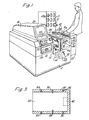
- the drilling machine shown in Figure 1 comprises a housing 8, an indexable cubic or cuboid table 10 and a spindle nose 12 mounted in the housing 8, the spindle nose 12 being spaced to one side of the table 10 so that it is generally at the same horizontal level asthetable, and so that there is a vertically extending gap 14 between the part 15 of the machine which supports the spindle nose and the part 16 which supports the table.
- the spindle nose 12 may be part of a turret arrangement (not shown).
- the machine further comprises an "egg-box" tool store 17, and a control computer 18 comprising a cathode ray tube 20, alphanumeric keyboards 22 and 24, and a memory tape unit 26.
- a further control panel 30 is provided underneath the keyboards of the computer 18, for direct manual control of the machine, as opposed to the automatic control by the computer.
- An automatically adjustable nozzle or injector32 is mounted within the housing 8 of the machine, underneath the table 10.
- a compressed air supply (not shown) is connected to this nozzle so that a jet of compressed air can be directed towards the underside of the table 10.
- a sloping swarf-collecting plate 40 extends underneath the gap 14 and also underneath table 10 down to a swarf-collecting tray (not shown) to one side of the machine.
- the table 10 is mounted on bearings 44 which allow it to be rotated by a drive motor (not shown) about a horizontal axis 45 which extends substantially at right angles to the axis of rotation of the spindle nose 12.
- the drive motor is adapted to rotate the table through 90° steps about the axis 45.
- the four sides 10a of the cubic table 10 which are parallel to its axis of rotation, and which constitute the working faces 10a of the table, are provided with a matrix of fixing formations 46 whereby clamps 48 can be used to hold workpieces of various shapes and sizes on those work faces.
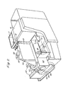
- the egg-box store 17 is provided with apertures 49 at least on one of its main faces to receive respective tools and is rotatable about a vertical axis, and also moveable vertically, to allow it to be moved from the position in which it is shown in Figure 1, which allows easy replacement by an operator of one or more of the tools which it holds, to the position it occupies in Figure 2 which allows easy selective access to the tool store 17 by the spindle nose 12, so that the latter can automatically remove any selected one of the tools held in the store 17.
- every tool is held by a tool holder 51, which is the same for each tool and has a tapered portion which fits into the spindle nose 12.
- Three drive motors 50, 52 and 54 are arranged to shift the spindle nose 12 along three mutually- perpendicular axes via respective drive couplings 56, 58 and 60: two horizontal axes being defined by guide tracks 62 and a side wall 64, and one vertical travel axis being defined by vertically extending flanges 65.
- a further drive motor 66 is connected to rotate the spindle nose 12 via a coupling 68.
- An armoured flexible conduit 70 (only part of which is shown in Figure 2) contains cables which interconnect the various drive motors 50, 52, 54 and 66 and other electrical components to the control computer 18, so that the computer can control the switching of these motors and other functions.
- Figure 2 also shows a zeroing or offsetting "target" 72. This detects the distance of the tip of a tool from the spindle nose 12 to provide the computer with the necessary zeroing or off-setting value from which, together with information as regards the size and shape of the tool and the workpiece, it can determine what movement of the spindle nose 12 is required to drill a hole of a given depth into the workpiece.
- FIG. 3 One construction for the target is shown in Figure 3. It comprises a wall 80 defining an open cavity 82, with two pairs of LED/photosensitive detector pairs 84 and 86 spaced apart axially in the wall of the target, and, between these pairs, compressed air injectors 88 and 90 for removing swarf from the tool.
- the first LED/photosensitive detector pair 84 is coupled to means (not shown) for slowing down horizontal movement of the tool as the latter is inserted into the cavity
- the second pair is coupled to means (not shown) for determining the exact position of the spindle nose 12 when the tip of the tool passes that second pair.
- the second pair may be replaced by a proximity switch 92 (shown in broken lines).
- the machine can be operated as follows: an operator 5 first loads the egg-box tool store 17 with the tools required for the variety of jobs which the machine is to perform.
- the computer is told which tools, including their sizes and shapes, are contained in the egg-box store, and in which hole of the egg-box store each tool is held.
- the computer is further informed as to the diameters, depths and other characteristics of the holes which the machine is to bore in each of a number of different shapes and sizes of workpiece.
- the first workpiece 100 is mounted on the face 10a of the table 10 which is for the time being uppermost.
- the operator may now press an indexing button 94 which causes the table to be rotated through 90° so that the workpiece 100 which he just attached to the uppermost face of the table 10 is now rotated downwardly to face the tool and spindle nose 12 of the machine.
- the computer 18 may now enter into the computer which particular workpiece he has just loaded. Alternatively he may load the machine in a particular order which he has already entered into the computer.
- the machine now carries out a drilling routine on the workpiece 100 he has just loaded leaving him free to load the next workpiece on the new face of the table 10 which is now uppermost.
- the second loading operation can be performed simultaneously with the drilling routine on the first workpiece.
- swarf can be blown from the first workpiece by the compressed-air injector 32 underneath the table 10, while at the same time the drill is operating on the second workpiece, and a third workpiece is being loaded onto the new face which is now uppermost.
- the spindle nose 12 is shifted rapidly back to the egg-box tool store 17 where a tool-change procedure is followed, the new tool is positioned in the nose 12, the tip of the tool is inserted into the zeroing or off-setting target 70, and the spindle nose 12 is then moved to the workpiece. All of these movements are performed with the use of the drive motors 50, 52 and 54 under the control of the computer 18. Because of the low inertia of the spindle nose 12 and the various other moveable parts involved, and also in view of the power of the drive motors themselves, a tool change can be accomplished in a matter of seconds, or possibly even more quickly than that.
- the machine has been described as a drilling machine, but it could be modified to perform milling or boring operations, for example.
Landscapes
- Engineering & Computer Science (AREA)
- Mechanical Engineering (AREA)
- Human Computer Interaction (AREA)
- Manufacturing & Machinery (AREA)
- Physics & Mathematics (AREA)
- General Physics & Mathematics (AREA)
- Automation & Control Theory (AREA)
- Automatic Tool Replacement In Machine Tools (AREA)
- Drilling And Boring (AREA)
- Jigs For Machine Tools (AREA)
- Machine Tool Units (AREA)
- Perforating, Stamping-Out Or Severing By Means Other Than Cutting (AREA)
- Finish Polishing, Edge Sharpening, And Grinding By Specific Grinding Devices (AREA)
- Turning (AREA)
- Apparatuses For Bulk Treatment Of Fruits And Vegetables And Apparatuses For Preparing Feeds (AREA)
- Footwear And Its Accessory, Manufacturing Method And Apparatuses (AREA)
- Manufacture Of Motors, Generators (AREA)
Abstract
Description
- The present invention relates to a method of operating a machine tool, the machine tool comprising:
- (a) a workpiece support having four support faces arranged around and substantially parallel to a horizontal indexing axis;
- (b) a spindle nose adjacent to the workpiece support and to one side thereof, so that a machining position in which a workpiece is held by the workpiece support when the machine tool is in use is horizontally displaced from the spindle nose and from a tool held by the spindle nose, and which is generally at the same horizontal level as the spindle nose and such a tool, whereby swarf is free to fall away from the workpiece without fouling the spindle nose or the workpiece itself; and
- (c) index means on which the workpiece support is mounted, the index means providing the horizontal indexing axis of rotation which is generally at the same horizontal level as the spindle nose and which is generally at right angles to the machine tool spindle axis, to enable the index means to be indexed through different positions, indexing of the workpiece support enabling one of the said four faces thereof to be turned from a workpiece loading position in which a workpiece can be mounted on thatface, to the said machining position in which such a workpiece is presented to the spindle nose, the spindle nose being moveable in three mutually perpendicular directions to enable the machine tool to operate on different parts of a workpiece whilst the latter is held stationary by the workpiece support, wherein the machine tool further comprises motor drive means coupled to the spindle nose to move the spindle nose in the three mutually perpendicular directions, a tool store accessible to the spindle nose by virtue of movement of the spindle nose, the tool store providing a plurality of storage locations for respective tools, and tool-change means to enable a tool for the time being held in the spindle nose to be changed for a selected tool stored in the tool store, the method comprising the steps of:
- (i) loading a workpiece atthe loading position on one of the said fourfaces of the workpiece support for the time being at that position;
- (ii) indexing the workpiece support about its indexing axis to the machining position in which the workpiece is presented to the spindle nose;
- (iii) machining different parts of the workpiece using movement of the spindle nose, to form a given component;
- (iv) changing the tool carried by the spindle nose in the course of that machining; and
- (v) controlling workpiece support indexing, machining and tool changing by computer.
- Such a method is disclosed in GB-A-1 263 911.
- The present invention seeks to improve the efficient production of a number of differently formed components.
- Accordingly, the present invention is directed to a method of operating a machine tool as set out in the opening paragraph of the present specification, characterised by the following steps:
- (vi) loading a second workpiece having a different form from the first-mentioned workpiece, on a second one of the said four faces 10(a) of the workpiece support, presented at the loading position whilst the first workpiece is being machined in the machining position, said loading of the second workpiece being effected independently of any tool changing operation arising during machining of the first workpiece;
- (vii) further indexing of the workpiece support following step (vi), to move the said second one of the said faces into the machining position;
- (viii) changing the computer programme, upon occurrence of step (vii), in order to control machining of the second workpiece into a second component different in form from the first mentioned component,
- whereby a succession of differently formed workpieces are loaded at one and the same loading position, and whereby components of different form are machined on the single indexable workpiece support in a selected order.
- Indexing of the workpiece support can afford safety in the event that a workpiece is attached to the workpiece support manually whilst another workpiece on a different part of the workpiece support is being machined.
- An example of a machine tool operated in accordance with the present invention is illustrated in the accompanying drawings, in which:
- Figure 1 shows a perspective elevational view of a drilling machine;
- Figure 2 shows a perspective elevational view of parts of the machine shown in Figure 1, an outer casing and certain peripherals of the machine having been removed to reveal internal drive components of the machine; and
- Figure 3 is a diagrammatic cross-sectional view of a zeroing or off-setting device of the machine.
- The drilling machine shown in Figure 1 comprises a housing 8, an indexable cubic or cuboid table 10 and a
spindle nose 12 mounted in the housing 8, thespindle nose 12 being spaced to one side of the table 10 so that it is generally at the same horizontal level asthetable, and so that there is a vertically extendinggap 14 between thepart 15 of the machine which supports the spindle nose and thepart 16 which supports the table. Thespindle nose 12 may be part of a turret arrangement (not shown). - The machine further comprises an "egg-box"
tool store 17, and acontrol computer 18 comprising acathode ray tube 20,alphanumeric keyboards memory tape unit 26. Afurther control panel 30 is provided underneath the keyboards of thecomputer 18, for direct manual control of the machine, as opposed to the automatic control by the computer. - An automatically adjustable nozzle or injector32 is mounted within the housing 8 of the machine, underneath the table 10. A compressed air supply (not shown) is connected to this nozzle so that a jet of compressed air can be directed towards the underside of the table 10. A sloping swarf-collecting
plate 40 extends underneath thegap 14 and also underneath table 10 down to a swarf-collecting tray (not shown) to one side of the machine. - The table 10 is mounted on
bearings 44 which allow it to be rotated by a drive motor (not shown) about ahorizontal axis 45 which extends substantially at right angles to the axis of rotation of thespindle nose 12. The drive motor is adapted to rotate the table through 90° steps about theaxis 45. The four sides 10a of the cubic table 10 which are parallel to its axis of rotation, and which constitute the working faces 10a of the table, are provided with a matrix offixing formations 46 whereby clamps 48 can be used to hold workpieces of various shapes and sizes on those work faces. - The egg-
box store 17 is provided withapertures 49 at least on one of its main faces to receive respective tools and is rotatable about a vertical axis, and also moveable vertically, to allow it to be moved from the position in which it is shown in Figure 1, which allows easy replacement by an operator of one or more of the tools which it holds, to the position it occupies in Figure 2 which allows easy selective access to thetool store 17 by thespindle nose 12, so that the latter can automatically remove any selected one of the tools held in thestore 17. To facilitate this, every tool is held by a tool holder 51, which is the same for each tool and has a tapered portion which fits into thespindle nose 12. - Three
drive motors spindle nose 12 along three mutually- perpendicular axes viarespective drive couplings guide tracks 62 and aside wall 64, and one vertical travel axis being defined by vertically extendingflanges 65. Afurther drive motor 66 is connected to rotate thespindle nose 12 via acoupling 68. - An armoured flexible conduit 70 (only part of which is shown in Figure 2) contains cables which interconnect the
various drive motors control computer 18, so that the computer can control the switching of these motors and other functions. Figure 2 also shows a zeroing or offsetting "target" 72. This detects the distance of the tip of a tool from thespindle nose 12 to provide the computer with the necessary zeroing or off-setting value from which, together with information as regards the size and shape of the tool and the workpiece, it can determine what movement of thespindle nose 12 is required to drill a hole of a given depth into the workpiece. - One construction for the target is shown in Figure 3. It comprises a wall 80 defining an
open cavity 82, with two pairs of LED/photosensitive detector pairs air injectors photosensitive detector pair 84 is coupled to means (not shown) for slowing down horizontal movement of the tool as the latter is inserted into the cavity, and the second pair is coupled to means (not shown) for determining the exact position of thespindle nose 12 when the tip of the tool passes that second pair. The second pair may be replaced by a proximity switch 92 (shown in broken lines). - The machine can be operated as follows: an operator 5 first loads the egg-
box tool store 17 with the tools required for the variety of jobs which the machine is to perform. The computer is told which tools, including their sizes and shapes, are contained in the egg-box store, and in which hole of the egg-box store each tool is held. The computer is further informed as to the diameters, depths and other characteristics of the holes which the machine is to bore in each of a number of different shapes and sizes of workpiece. The first workpiece 100 is mounted on the face 10a of the table 10 which is for the time being uppermost. The operator may now press anindexing button 94 which causes the table to be rotated through 90° so that the workpiece 100 which he just attached to the uppermost face of the table 10 is now rotated downwardly to face the tool andspindle nose 12 of the machine. If thecomputer 18 has not been informed of the order in which workpieces are to be operated on, he may now enter into the computer which particular workpiece he has just loaded. Alternatively he may load the machine in a particular order which he has already entered into the computer. The machine now carries out a drilling routine on the workpiece 100 he has just loaded leaving him free to load the next workpiece on the new face of the table 10 which is now uppermost. The second loading operation can be performed simultaneously with the drilling routine on the first workpiece. On the next indexing of the table 10, swarf can be blown from the first workpiece by the compressed-air injector 32 underneath the table 10, while at the same time the drill is operating on the second workpiece, and a third workpiece is being loaded onto the new face which is now uppermost. - In this way, it can be seen that idleing time of the machine is very much reduced, or completely done away with. It can also be seen that the swarf tends to fall away from the drilling equipment and the table 10 on which the workpiece is supported, through the
vertical gap 14, and that the workpiece is further cleaned by the compressed air injector 32 which is on the underneath side of the table 10. In this way, neither the workpiece nor the drilling equipment is fouled by swarf and, as each work face with its workpiece becomes the uppermost face of the table again it provides a finished product clean of swarf and ready for removal by the operator. - Although operation of the machine has been described with reference to an operator, it will be appreciated that the latter functions could be performed automatically by robots.
- During a drilling routine for any given workpiece, at each change of tool the
spindle nose 12 is shifted rapidly back to the egg-box tool store 17 where a tool-change procedure is followed, the new tool is positioned in thenose 12, the tip of the tool is inserted into the zeroing or off-settingtarget 70, and thespindle nose 12 is then moved to the workpiece. All of these movements are performed with the use of thedrive motors computer 18. Because of the low inertia of thespindle nose 12 and the various other moveable parts involved, and also in view of the power of the drive motors themselves, a tool change can be accomplished in a matter of seconds, or possibly even more quickly than that. - The machine has been described as a drilling machine, but it could be modified to perform milling or boring operations, for example.
Claims (1)
- A method of operating a machine tool, the machine tool comprising:(a) a workpiece support (10) having four support faces arranged around and substantially parallel to a horizontal indexing axis;(b) a spindle nose (12) adjacent to the workpiece support (10) and to one side thereof, so that a machining position in which a workpiece is held by the workpiece support when the machine tool is in use is horizontally displaced from the spindle nose (12) and from a tool held by the spindle nose (12), and which is generally at the same horizontal level as the spindle nose (12) and such a tool, whereby swarf is free to fall away from the workpiece (100) without fouling the spindle nose (12) or the workpiece (10) itself; and(c) index means (44) on which the workpiece support (10) is mounted, the index means (44) providing the horizontal indexing axis of rotation which is generally at the same horizontal level as the spindle nose (12) and which is generally at right angles to the machine tool spindle axis, to enable the index means (44) to be indexed through different positions, indexing of the workpiece support (10) enabling one of the said four faces (10a) thereof to be turned from a workpiece loading position in which a workpiece (100) can be mounted on that face (10a), to the said machining position in which such a workpiece (100) is presented to the spindle nose (12), the spindle nose (12) being moveable in three mutually perpendicular directions to enable the machine tool to operate on different parts of a workpiece (100) whilstthe latter is held stationary by the workpiece support (10), wherein the machine tool further comprises motor drive means (50, 52 and 54) coupled to the spindle nose (12) to move the spindle nose (12) in the three mutually perpendicular directions, a tool store (17) accessible to the spindle nose (12) by virtue of movement of the spindle nose, the tool store providing a plurality of storage locations (49) for respective tools, and tool-change means to enable a tool for the time being held in the spindle nose (12) to be changed for a selected tool stored in the tool store, the method comprising the steps of:(i) loading a workpiece at the loading position on one of the said four faces of the workpiece support (10) for the time being at that position;(ii) indexing the workpiece support (10) about its indexing axis (45) to the machining position in which the workpiece is presented to the spindle nose (12);(iii) machining different parts of the workpiece using movement of the spindle nose (12), to form a given component;(iv) changing the tool carried by the spindle nose (12) in the course of that machining;(v) controlling workpiece support indexing, machining and tool changing by computer;
characterised by the following steps:(vi) loading a second workpiece having a different form from the first-mentioned workpiece, on a second one of the said four faces (10a) of the workpiece support (10), presented at the loading position whilst the first workpiece is being machined in the machining position, said loading of the second workpiece being effected independently of any tool changing operation arising during machining of the first workpiece;(vii) further indexing of the workpiece support (10) following step (vi), to move the said second one of the said faces (10a) into the machining position;(viii) changing the computer programme, upon occurrence of step (vii), in orderto control machining of the second workpiece into a second component different in form from the first mentioned component,whereby a succession of differently formed workpieces are loaded at one and the same loading position, and whereby components of different form are machined on the single indexable workpiece support in a selected order.
Priority Applications (1)
| Application Number | Priority Date | Filing Date | Title |
|---|---|---|---|
| AT83302378T ATE55302T1 (en) | 1982-05-05 | 1983-04-27 | METHOD OF OPERATING A MACHINE TOOL. |
Applications Claiming Priority (2)
| Application Number | Priority Date | Filing Date | Title |
|---|---|---|---|
| GB8212912 | 1982-05-05 | ||
| GB08212912A GB2119295B (en) | 1982-05-05 | 1982-05-05 | Machine tool |
Publications (3)
| Publication Number | Publication Date |
|---|---|
| EP0093575A2 EP0093575A2 (en) | 1983-11-09 |
| EP0093575A3 EP0093575A3 (en) | 1985-12-18 |
| EP0093575B1 true EP0093575B1 (en) | 1990-08-08 |
Family
ID=10530165
Family Applications (1)
| Application Number | Title | Priority Date | Filing Date |
|---|---|---|---|
| EP83302378A Expired - Lifetime EP0093575B1 (en) | 1982-05-05 | 1983-04-27 | A method of operating a machine tool |
Country Status (8)
| Country | Link |
|---|---|
| US (1) | US4651404A (en) |
| EP (1) | EP0093575B1 (en) |
| JP (1) | JPS5942233A (en) |
| AT (1) | ATE55302T1 (en) |
| CA (1) | CA1220928A (en) |
| DE (1) | DE3381786D1 (en) |
| ES (1) | ES522074A0 (en) |
| GB (1) | GB2119295B (en) |
Families Citing this family (15)
| Publication number | Priority date | Publication date | Assignee | Title |
|---|---|---|---|---|
| GB2167325B (en) * | 1984-11-22 | 1987-08-26 | Wavis Engineering Dev Co Limit | Multi-spindle machining centre |
| JPS61168871A (en) * | 1985-01-19 | 1986-07-30 | Sanyo Electric Co Ltd | Hydrogen occlusion electrode |
| FR2599654B1 (en) * | 1986-06-06 | 1988-09-09 | Bucaille Bernard | MACHINING CENTER |
| US5590454A (en) * | 1994-12-21 | 1997-01-07 | Richardson; Kendrick E. | Method and apparatus for producing parts by layered subtractive machine tool techniques |
| US6190294B1 (en) * | 1997-09-30 | 2001-02-20 | Toyoda Koki Kabushiki Kaisha | Horizontal machine tool |
| JP3794938B2 (en) * | 2000-10-04 | 2006-07-12 | 株式会社牧野フライス製作所 | Processing machine equipment |
| US6561062B2 (en) * | 2001-01-18 | 2003-05-13 | Delta International Machinery Corp. | Lathe |
| USD923669S1 (en) * | 2016-10-13 | 2021-06-29 | Chetocorporation, S.A. | Machine tool for drilling deep holes |
| USD869523S1 (en) * | 2016-10-13 | 2019-12-10 | Chetocorporation, S.A. | Machine tool for drilling deep holes |
| USD929475S1 (en) * | 2016-10-13 | 2021-08-31 | Chetocorporation, S.A. | Machine tool for drilling deep holes |
| USD884754S1 (en) * | 2018-10-04 | 2020-05-19 | Chetocorporation, S.A. | Machine tool for drilling deep holes |
| CN110560756B (en) * | 2019-07-29 | 2020-09-22 | 新昌县凌智机械有限公司 | Multifunctional automatic tool changing milling machine |
| USD969180S1 (en) | 2019-12-26 | 2022-11-08 | Nagase Integrex Co., Ltd. | Machine tool |
| USD974422S1 (en) * | 2020-10-23 | 2023-01-03 | Dallan S.P.A. | Cutting machine |
| USD974424S1 (en) * | 2020-10-23 | 2023-01-03 | Dallan S.P.A. | Control desk for machine tools |
Citations (4)
| Publication number | Priority date | Publication date | Assignee | Title |
|---|---|---|---|---|
| GB1083742A (en) * | 1963-09-09 | 1967-09-20 | Mueller Hellmut Dipl -Ing | Machine tool |
| US3361033A (en) * | 1962-02-20 | 1968-01-02 | Hans Deckel | Rotating and swiveling clamping table for machine tools |
| GB1263911A (en) * | 1968-03-13 | 1972-02-16 | David Theodore Nelson Williams | Improvements in or relating to machine tools |
| US4012818A (en) * | 1973-11-14 | 1977-03-22 | Scharmann & Co. | Boring mill and milling device with a tool magazine |
Family Cites Families (22)
| Publication number | Priority date | Publication date | Assignee | Title |
|---|---|---|---|---|
| GB591788A (en) * | 1944-10-10 | 1947-08-28 | Siemens Schuckert Great Britai | Improvements in drilling and like machine tools |
| US1539471A (en) * | 1920-06-29 | 1925-05-26 | Deuring Fritz Richard | Milling machine |
| US2271848A (en) * | 1938-11-02 | 1942-02-03 | Bradford Machine Tool Company | Indexing mechanism |
| US2224108A (en) * | 1939-04-15 | 1940-12-03 | Ingersoll Milling Machine Co | Machine tool |
| US2353480A (en) * | 1941-08-28 | 1944-07-11 | Newman M Marsilius | Milling machine |
| US2953069A (en) * | 1954-10-18 | 1960-09-20 | Earl R Lowe | Device for multiple machining of work pieces |
| NL256631A (en) * | 1959-06-23 | |||
| FR1434132A (en) * | 1964-08-06 | 1966-04-08 | Derefa Etablissement Pour Le D | Rotary workpiece support device |
| DE1552393B1 (en) * | 1966-10-31 | 1969-10-16 | Froriep Gmbh Maschf | Heavy machine tool |
| GB1256876A (en) * | 1968-03-21 | 1971-12-15 | ||
| DE1961567A1 (en) * | 1968-12-24 | 1970-09-03 | Werkzeugmasch Heckert Veb | Device for changing workpieces on machine tools |
| US3587630A (en) * | 1969-05-02 | 1971-06-28 | Deere & Co | Pressure-compensated flow control valve |
| DE1963209A1 (en) * | 1969-12-17 | 1971-06-24 | Frank Rudolf Dipl Ing | Indexing table or indexing drum machine |
| FR2094268A5 (en) * | 1970-06-15 | 1972-02-04 | Huard Ucf | |
| US4075753A (en) * | 1975-10-17 | 1978-02-28 | The Monarch Machine Tool Company | Plural slide machine |
| GB1543701A (en) * | 1978-01-11 | 1979-04-04 | British Leyland Cars Ltd | Method and apparatus for the production of a multi-contoured component by broaching |
| GB1601698A (en) * | 1977-08-20 | 1981-11-04 | Gen Eng Radcliffe | Extrusion method and apparatus therefor |
| US4218815A (en) * | 1978-09-18 | 1980-08-26 | Cumming Noel N | Modular transfer machine |
| JPS57102733A (en) * | 1980-12-16 | 1982-06-25 | Toyoda Mach Works Ltd | Automatic dimension correcting apparatus for spare tool |
| US4422265A (en) * | 1981-06-15 | 1983-12-27 | Jacobi-Branston Inc. | Multistation grinding machine |
| US4423546A (en) * | 1981-09-04 | 1984-01-03 | W. A. Whitney Corp. | Punch press with automatic tool changer |
| US4425061A (en) * | 1981-09-14 | 1984-01-10 | Colt Industries Operating Corp | Tool setting device for machining center |
-
1982
- 1982-05-05 GB GB08212912A patent/GB2119295B/en not_active Expired
-
1983
- 1983-04-27 DE DE8383302378T patent/DE3381786D1/en not_active Expired - Fee Related
- 1983-04-27 AT AT83302378T patent/ATE55302T1/en not_active IP Right Cessation
- 1983-04-27 EP EP83302378A patent/EP0093575B1/en not_active Expired - Lifetime
- 1983-04-28 CA CA000426951A patent/CA1220928A/en not_active Expired
- 1983-05-04 ES ES522074A patent/ES522074A0/en active Granted
- 1983-05-05 US US06/491,800 patent/US4651404A/en not_active Expired - Fee Related
- 1983-05-06 JP JP58079184A patent/JPS5942233A/en active Pending
Patent Citations (4)
| Publication number | Priority date | Publication date | Assignee | Title |
|---|---|---|---|---|
| US3361033A (en) * | 1962-02-20 | 1968-01-02 | Hans Deckel | Rotating and swiveling clamping table for machine tools |
| GB1083742A (en) * | 1963-09-09 | 1967-09-20 | Mueller Hellmut Dipl -Ing | Machine tool |
| GB1263911A (en) * | 1968-03-13 | 1972-02-16 | David Theodore Nelson Williams | Improvements in or relating to machine tools |
| US4012818A (en) * | 1973-11-14 | 1977-03-22 | Scharmann & Co. | Boring mill and milling device with a tool magazine |
Non-Patent Citations (3)
| Title |
|---|
| Brochure of Machining Center (Giddings & Lewis-Bickford, 1977) * |
| Metalworking Production, 19.06.68, p. 113 * |
| Werkstattstechnik 12/82, p. 673-678 * |
Also Published As
| Publication number | Publication date |
|---|---|
| GB2119295B (en) | 1986-08-28 |
| CA1220928A (en) | 1987-04-28 |
| ATE55302T1 (en) | 1990-08-15 |
| JPS5942233A (en) | 1984-03-08 |
| EP0093575A2 (en) | 1983-11-09 |
| DE3381786D1 (en) | 1990-09-13 |
| US4651404A (en) | 1987-03-24 |
| ES8500783A1 (en) | 1984-11-16 |
| ES522074A0 (en) | 1984-11-16 |
| EP0093575A3 (en) | 1985-12-18 |
| GB2119295A (en) | 1983-11-16 |
Similar Documents
| Publication | Publication Date | Title |
|---|---|---|
| EP0093575B1 (en) | A method of operating a machine tool | |
| US6745455B2 (en) | Automatic milling and drilling machine | |
| US7506423B2 (en) | Multi-axis turning center and turning method | |
| EP1116548A2 (en) | A machine tool having a vertical main spindle and a method of making the same | |
| EP0349641B1 (en) | Machine tool | |
| US6457919B1 (en) | Multi-purpose machine tool for high volume secondary operations | |
| US7451533B2 (en) | NC automatic lathe | |
| US3486209A (en) | Turret lathe | |
| US7013543B2 (en) | Vertical machining center | |
| EP3919225A1 (en) | Automatic tool changer and control method therefor, and machine tool including same | |
| EP3733341A1 (en) | Tool magazine of machine tool | |
| JPH02504610A (en) | drilling and milling equipment | |
| CN113382821A (en) | Machine tool and method for operating the same | |
| JPH04283037A (en) | Machine tool | |
| EP0421580A2 (en) | Machine tool with several heads, particularly for woodworking | |
| CN112888529B (en) | machine tool | |
| GB2167325A (en) | Multi-spindle machining centre | |
| JPS61265234A (en) | Machine tool | |
| CN116475848A (en) | Multi-working-procedure integrated machine tool | |
| US6694849B1 (en) | Lathe | |
| JPH0748356Y2 (en) | Tool changer | |
| JP2639700B2 (en) | Work supply and recovery device for machine tools | |
| CN216829871U (en) | Snatch mechanism and PCB processing equipment | |
| JP2008105158A (en) | Vertical type machine tool | |
| JPH0890303A (en) | Numerically controlled automatic lathe |
Legal Events
| Date | Code | Title | Description |
|---|---|---|---|
| PUAI | Public reference made under article 153(3) epc to a published international application that has entered the european phase |
Free format text: ORIGINAL CODE: 0009012 |
|
| AK | Designated contracting states |
Designated state(s): AT BE CH DE FR IT LI NL SE |
|
| PUAL | Search report despatched |
Free format text: ORIGINAL CODE: 0009013 |
|
| AK | Designated contracting states |
Designated state(s): AT BE CH DE FR IT LI NL SE |
|
| 17P | Request for examination filed |
Effective date: 19860616 |
|
| 17Q | First examination report despatched |
Effective date: 19870401 |
|
| GRAA | (expected) grant |
Free format text: ORIGINAL CODE: 0009210 |
|
| AK | Designated contracting states |
Kind code of ref document: B1 Designated state(s): AT BE CH DE FR IT LI NL SE |
|
| REF | Corresponds to: |
Ref document number: 55302 Country of ref document: AT Date of ref document: 19900815 Kind code of ref document: T |
|
| REF | Corresponds to: |
Ref document number: 3381786 Country of ref document: DE Date of ref document: 19900913 |
|
| ET | Fr: translation filed | ||
| ITF | It: translation for a ep patent filed | ||
| PGFP | Annual fee paid to national office [announced via postgrant information from national office to epo] |
Ref country code: CH Payment date: 19910410 Year of fee payment: 9 |
|
| PGFP | Annual fee paid to national office [announced via postgrant information from national office to epo] |
Ref country code: FR Payment date: 19910412 Year of fee payment: 9 |
|
| PGFP | Annual fee paid to national office [announced via postgrant information from national office to epo] |
Ref country code: SE Payment date: 19910422 Year of fee payment: 9 |
|
| PGFP | Annual fee paid to national office [announced via postgrant information from national office to epo] |
Ref country code: AT Payment date: 19910426 Year of fee payment: 9 |
|
| PGFP | Annual fee paid to national office [announced via postgrant information from national office to epo] |
Ref country code: NL Payment date: 19910430 Year of fee payment: 9 |
|
| PGFP | Annual fee paid to national office [announced via postgrant information from national office to epo] |
Ref country code: BE Payment date: 19910514 Year of fee payment: 9 |
|
| PGFP | Annual fee paid to national office [announced via postgrant information from national office to epo] |
Ref country code: DE Payment date: 19910517 Year of fee payment: 9 |
|
| PLBE | No opposition filed within time limit |
Free format text: ORIGINAL CODE: 0009261 |
|
| STAA | Information on the status of an ep patent application or granted ep patent |
Free format text: STATUS: NO OPPOSITION FILED WITHIN TIME LIMIT |
|
| 26N | No opposition filed | ||
| PG25 | Lapsed in a contracting state [announced via postgrant information from national office to epo] |
Ref country code: AT Effective date: 19920427 |
|
| PG25 | Lapsed in a contracting state [announced via postgrant information from national office to epo] |
Ref country code: SE Effective date: 19920428 |
|
| PG25 | Lapsed in a contracting state [announced via postgrant information from national office to epo] |
Ref country code: LI Effective date: 19920430 Ref country code: CH Effective date: 19920430 Ref country code: BE Effective date: 19920430 |
|
| BERE | Be: lapsed |
Owner name: LESLIE HARTRIDGE LTD Effective date: 19920430 |
|
| PG25 | Lapsed in a contracting state [announced via postgrant information from national office to epo] |
Ref country code: NL Effective date: 19921101 |
|
| NLV4 | Nl: lapsed or anulled due to non-payment of the annual fee | ||
| PG25 | Lapsed in a contracting state [announced via postgrant information from national office to epo] |
Ref country code: FR Effective date: 19921230 |
|
| REG | Reference to a national code |
Ref country code: CH Ref legal event code: PL |
|
| PG25 | Lapsed in a contracting state [announced via postgrant information from national office to epo] |
Ref country code: DE Effective date: 19930101 |
|
| REG | Reference to a national code |
Ref country code: FR Ref legal event code: ST |
|
| EUG | Se: european patent has lapsed |
Ref document number: 83302378.1 Effective date: 19921108 |