EP0093573A1 - Scheibenbremsen für Fahrzeuge - Google Patents
Scheibenbremsen für Fahrzeuge Download PDFInfo
- Publication number
- EP0093573A1 EP0093573A1 EP83302376A EP83302376A EP0093573A1 EP 0093573 A1 EP0093573 A1 EP 0093573A1 EP 83302376 A EP83302376 A EP 83302376A EP 83302376 A EP83302376 A EP 83302376A EP 0093573 A1 EP0093573 A1 EP 0093573A1
- Authority
- EP
- European Patent Office
- Prior art keywords
- brake
- coupling
- piston
- thrust member
- cylinder
- Prior art date
- Legal status (The legal status is an assumption and is not a legal conclusion. Google has not performed a legal analysis and makes no representation as to the accuracy of the status listed.)
- Withdrawn
Links
- 230000008878 coupling Effects 0.000 claims abstract description 23
- 238000010168 coupling process Methods 0.000 claims abstract description 23
- 238000005859 coupling reaction Methods 0.000 claims abstract description 23
- 230000006835 compression Effects 0.000 claims abstract description 9
- 238000007906 compression Methods 0.000 claims abstract description 9
- 238000006243 chemical reaction Methods 0.000 claims abstract description 5
- 239000004575 stone Substances 0.000 claims description 6
- 239000000463 material Substances 0.000 claims description 3
- 238000010276 construction Methods 0.000 abstract description 6
- 238000007789 sealing Methods 0.000 abstract description 5
- 230000007246 mechanism Effects 0.000 description 11
- 230000005540 biological transmission Effects 0.000 description 4
- 230000000295 complement effect Effects 0.000 description 4
- 230000008859 change Effects 0.000 description 2
- 239000012530 fluid Substances 0.000 description 2
- 230000002093 peripheral effect Effects 0.000 description 2
- 230000008719 thickening Effects 0.000 description 2
- 239000011324 bead Substances 0.000 description 1
- 230000008901 benefit Effects 0.000 description 1
- 239000013536 elastomeric material Substances 0.000 description 1
- 239000002783 friction material Substances 0.000 description 1
- 238000005461 lubrication Methods 0.000 description 1
- 239000002184 metal Substances 0.000 description 1
- 230000004048 modification Effects 0.000 description 1
- 238000012986 modification Methods 0.000 description 1
- 230000000717 retained effect Effects 0.000 description 1
- 239000007787 solid Substances 0.000 description 1
- 230000007480 spreading Effects 0.000 description 1
- XLYOFNOQVPJJNP-UHFFFAOYSA-N water Substances O XLYOFNOQVPJJNP-UHFFFAOYSA-N 0.000 description 1
Images
Classifications
-
- F—MECHANICAL ENGINEERING; LIGHTING; HEATING; WEAPONS; BLASTING
- F16—ENGINEERING ELEMENTS AND UNITS; GENERAL MEASURES FOR PRODUCING AND MAINTAINING EFFECTIVE FUNCTIONING OF MACHINES OR INSTALLATIONS; THERMAL INSULATION IN GENERAL
- F16D—COUPLINGS FOR TRANSMITTING ROTATION; CLUTCHES; BRAKES
- F16D55/00—Brakes with substantially-radial braking surfaces pressed together in axial direction, e.g. disc brakes
- F16D55/02—Brakes with substantially-radial braking surfaces pressed together in axial direction, e.g. disc brakes with axially-movable discs or pads pressed against axially-located rotating members
- F16D55/04—Brakes with substantially-radial braking surfaces pressed together in axial direction, e.g. disc brakes with axially-movable discs or pads pressed against axially-located rotating members by moving discs or pads away from one another against radial walls of drums or cylinders
- F16D55/14—Brakes with substantially-radial braking surfaces pressed together in axial direction, e.g. disc brakes with axially-movable discs or pads pressed against axially-located rotating members by moving discs or pads away from one another against radial walls of drums or cylinders with self-tightening action, e.g. by means of coacting helical surfaces or balls and inclined surfaces
- F16D55/18—Brakes actuated by a fluid-pressure device arranged in or on the brake
-
- F—MECHANICAL ENGINEERING; LIGHTING; HEATING; WEAPONS; BLASTING
- F16—ENGINEERING ELEMENTS AND UNITS; GENERAL MEASURES FOR PRODUCING AND MAINTAINING EFFECTIVE FUNCTIONING OF MACHINES OR INSTALLATIONS; THERMAL INSULATION IN GENERAL
- F16D—COUPLINGS FOR TRANSMITTING ROTATION; CLUTCHES; BRAKES
- F16D55/00—Brakes with substantially-radial braking surfaces pressed together in axial direction, e.g. disc brakes
- F16D55/02—Brakes with substantially-radial braking surfaces pressed together in axial direction, e.g. disc brakes with axially-movable discs or pads pressed against axially-located rotating members
- F16D55/04—Brakes with substantially-radial braking surfaces pressed together in axial direction, e.g. disc brakes with axially-movable discs or pads pressed against axially-located rotating members by moving discs or pads away from one another against radial walls of drums or cylinders
- F16D55/14—Brakes with substantially-radial braking surfaces pressed together in axial direction, e.g. disc brakes with axially-movable discs or pads pressed against axially-located rotating members by moving discs or pads away from one another against radial walls of drums or cylinders with self-tightening action, e.g. by means of coacting helical surfaces or balls and inclined surfaces
-
- F—MECHANICAL ENGINEERING; LIGHTING; HEATING; WEAPONS; BLASTING
- F16—ENGINEERING ELEMENTS AND UNITS; GENERAL MEASURES FOR PRODUCING AND MAINTAINING EFFECTIVE FUNCTIONING OF MACHINES OR INSTALLATIONS; THERMAL INSULATION IN GENERAL
- F16D—COUPLINGS FOR TRANSMITTING ROTATION; CLUTCHES; BRAKES
- F16D65/00—Parts or details
- F16D65/38—Slack adjusters
- F16D65/40—Slack adjusters mechanical
- F16D65/52—Slack adjusters mechanical self-acting in one direction for adjusting excessive play
- F16D65/56—Slack adjusters mechanical self-acting in one direction for adjusting excessive play with screw-thread and nut
-
- F—MECHANICAL ENGINEERING; LIGHTING; HEATING; WEAPONS; BLASTING
- F16—ENGINEERING ELEMENTS AND UNITS; GENERAL MEASURES FOR PRODUCING AND MAINTAINING EFFECTIVE FUNCTIONING OF MACHINES OR INSTALLATIONS; THERMAL INSULATION IN GENERAL
- F16D—COUPLINGS FOR TRANSMITTING ROTATION; CLUTCHES; BRAKES
- F16D2125/00—Components of actuators
- F16D2125/18—Mechanical mechanisms
- F16D2125/20—Mechanical mechanisms converting rotation to linear movement or vice versa
- F16D2125/34—Mechanical mechanisms converting rotation to linear movement or vice versa acting in the direction of the axis of rotation
- F16D2125/36—Helical cams, Ball-rotating ramps
-
- F—MECHANICAL ENGINEERING; LIGHTING; HEATING; WEAPONS; BLASTING
- F16—ENGINEERING ELEMENTS AND UNITS; GENERAL MEASURES FOR PRODUCING AND MAINTAINING EFFECTIVE FUNCTIONING OF MACHINES OR INSTALLATIONS; THERMAL INSULATION IN GENERAL
- F16D—COUPLINGS FOR TRANSMITTING ROTATION; CLUTCHES; BRAKES
- F16D2125/00—Components of actuators
- F16D2125/18—Mechanical mechanisms
- F16D2125/58—Mechanical mechanisms transmitting linear movement
- F16D2125/68—Lever-link mechanisms, e.g. toggles with change of force ratio
Definitions
- This invention relates to disc brakes for vehicles of the kind in which at least one friction disc rotatable within a stationary housing is adapted to be moved into engagement with a relatively stationary surface, and actuating means are provided for moving the disc into engagement with the said surface to apply the brake, the actuating means comprising at least one pressure plate which is located in the housing adjacent to the disc, and balls housed in recesses in the pressure plate and an adjacent face of a reaction member, actuating movement of the pressure plate relative to the reaction member in the plane of the pressure plate being accompanied by axial movement of the pressure plate to urge the friction disc into engagement with the stationary surface.
- the actuating movement of the pressure plate can be effected hydraulically by an actuator comprising a cylinder and piston assembly of which the axis is substantially normal to that of the brake and of which one component is fixed relative to the housing and the other is movable and acts through a so-called spherical rocking thrust coupling associated with a pull-rod passing through the actuator with a substantial clearance, and the pull-rod is adapted for connection to a manually-operable brake applying device, a hand lever for example, by means of which the pull-rod can be moved in a brake-applying direction and relative to the cylinder and piston assembly.
- a brake of that kind is referred to below as "a brake of the kind set forth” and is particularly suitable for use in tractors and like vehicles.
- GB-A-2 067 692 discloses a brake of the kind set forth in which a laterally slidable thrust member is placed between the movable component and the spherical rocking coupling in order to relieve the movable component of side loads on angular movement of the pull-rod when the brake is applied hydraulically.
- a laterally slidable thrust member is placed between the movable component and the spherical rocking coupling in order to relieve the movable component of side loads on angular movement of the pull-rod when the brake is applied hydraulically.
- a thrust member is disposed between the movable component and the spherical rocking coupling, and the thrust member is engageable with a thrust transmitting face on the movable component for sliding movement in a transverse direction with respect to the axis of the piston and cylinder assembly, the thrust member and the spherical rocking coupling being biassed towards each other so that the thrust member is restrained from moving radially with respect to the coupling when brake application is effected by the manually-operable brake applying device.
- the biassing may be achieved by a compression spring which acts on either the thrust member or the coupling.
- the spring acts between the thrust member and a shoulder on the piston of the piston and cylinder assembly or the spring may act between the coupling and a stone guard for the adjacent end of the cylinder.
- the biassing is achieved by the resilience in the material of a boot for sealing an adjacent end of the housing.
- the boot seals a space between the spherical rocking coupling and the adjacent wall of the housing.
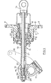
- the mechanism includes an hydraulic cylinder 1 which is open at both ends and has an outwardly extending annular flange 2 at one end containing axial bolt holes 3.
- the cylinder is, in use, bolted to a housing of the brake which is formed with a peripheral opening surrounded by a seating for the flange 2.
- the axis of the cylinder 1 is substantially at right angles to that of the brake.
- the cylinder 1 has a stepped bore 4 in which works a hollow annular stepped piston 5 sealed by axially spaced seals 6.
- the working space of the cylinder is the annular space 7 around the piston at the step in diameter and a connection (not shown) is made to this space from a master cylinder or other source of fluid under pressure.
- Outward movement of the piston is limited by a circlip 8 located in an annular groove in the piston wall adjacent to its open inner end.
- annular thrust member 9 Seating on the outer end of the piston is an annular thrust member 9 having a part-spherical outer surface co-operating with a complementary surface on the inner end of a collar 10 to form a spherical rocking coupling.
- the thrust member 9 is of a low-friction material and has a sliding engagement for radial movement with the outer end of the piston 5 which is of greater diameter.
- the thrust member 9 is urged outwardly away from the piston 5 by a compression spring 11 located within the outer end of the piston 5. The inner end of the spring 11 bears against an annular abutment 12 formed on the inside of the piston.
- the collar 10 is associated with a force transmitting assembly 13 for transmitting a brake-applying force from the piston 5 to a clevis 14 which, in use, is pivoted to opposed toggle levers of which the opposite ends are connected to lugs on the pressure plates of a brake of the self-energising spreading type.
- a brake is illustrated in Figures.4 and 5 of GB-A-2 067 692 and may be of the dry or of the oil-immersed type).
- the force transmitting assembly 13 comprises a trunnion 15 which is journalled for rotation in a bifurcated crank 16 fast with a rotatable transverse shaft 17, and a radial brake-applying lever 18 is also fast with the shaft 17.
- a compression tube in the form of a distance piece 19 abuts at opposite ends between the collar 10 and a flat 20 on the trunnion 15.
- a pull-rod 21 extending through the tube 19 and the collar 10 also extends at its outer end through an opening in the trunnion 15 to act on a second flat 22 parallel with and diametrically opposed to the flat 20 through a thrust washer 23, a nut 24 and a lock nut 25.
- the inner end of the rod 21 is coupled to the clevis 14.
- Circumferential movement of the clevis 14 with the toggle levers when the brake is applied is accommodated by the thrust member 9 sliding with respect to the outer end of the piston 5, with angular movement of the assembly 13 being accommodated by the collar 10 rocking in the recess in the thrust member 9.
- the lever 18 When the brake is to be applied mechanically or manually, for parking or in an emergency, the lever 18 is moved angularly by a force applied to its outer end by a transmission line in the form of a rod or cable. The angular movement of the lever 18 imparts corresponding movement to the crank 16 which, in turn, withdraws the rod 21 from the brake housing to withdraw the toggle levers as described above.
- the tube 19, collar 10 and thrust member 9 are urged outwardly by the spring 11 so that they all travel in unison with the rod 21, the thrust member 9 becoming separated from the piston 5 which remains unaffected.
- the collar 10 thus remains correctly seated on the thrust member 9 so that when the lever 18 is returned to release the brake there is no danger of the rod 21 being held off its correct released position by the thrust member 9 having become displaced radially with respect to the collar 10.
- the spring is, of course, not strong enough to move the crank 16.
- the collar 10 and tube 19 may be formed in one piece.
- wear in the friction linings may be compensated for by screwing the nut 24 further onto the rod 21 to shorten its effective length.
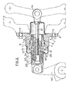
- this calls for periodical manual checking and adjustment which is avoided in the embodiment of Figure 2, which will now be described.
- the collar 10 of Figure 1 is replaced by a sleeve 10' in screw threaded engagement with an end portion of the pull-rod 21.
- the inner end of the sleeve 10' forms a spherical rocking coupling with the thrust member 9.
- the outer end of the sleeve is slidably received within a housing 28 which is formed in two parts for ease of assembly.
- the outer end of the housing 28 is pivotally connected to a crank 16' which is arranged to be operated by a transmission line in a similar manner to the crank 16 of Figure 1.
- Outward movement of the housing 28 relative to the sleeve 10' is limited by abutment of the end of a coarse fast thread 29 on the outside of the sleeve 10' with a radial shoulder 30 surrounding an opening at the inner end of the housing 28 and through which the sleeve 10' is otherwise. guided to slide.
- a clutch ring 31 is carried in screw-threaded engagement with the fast thread 29 and is urged inwardly towards the shoulder 30 by a compression spring 32 so that an inclined peripheral face 33 of the clutch ring 31 is in frictional engagement with a complementary clutch face 34 on the inside of the housing 28.
- a degree of back lash defining the brake clearances is provided between the threads of the ring 31 and the sleeve 10'. Unless adjustment is required, the clutch ring 31 is held in frictional engagement with the face 34 during the brake-applying and brake-release operations.
- the piston 5 transmits an outward thrust to the sleeve 10' which, because of its screw-threaded engagement with the pull-rod 21, applies a tensile force to the rod 21 to apply the brake, and angular movement of the rod 21 is accommodated by transverse sliding of the thrust member 9.
- the sleeve 10' moves rearwardly relative to the housing 28 which is held relatively stationary by the lever 16'.
- the ring 31 is carried by the sleeve 10' out of frictional engagement with the clutch face 34 against the force in the spring 32.
- crank 16' moves angularly and acts through the abutment of the shoulder 30 on the housing 28 with the thread 29 to withdraw the rod 21 and apply the brake.
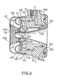
- the spring 11 is replaced by a compression spring 40 of conical outline, and the flexible boot 35 is enclosed within a snap-on stone guard 41 which encloses the adjacent end of the cylinder 1.
- the stone guard 41 comprises a metal pressing having a cylindrical skirt 42 which receives a spigot portion 43 on that end of the cylinder 1.
- the skirt 42 has an inwardly directed radial rib 44 at its free end for engagement in a radial groove 45 in the spigot portion 43 to retain the guard 41 against axial movement with respect to the cylinder 1.
- a bead or thickening 46 at the outer edge of the boot 35 is received in a groove defined between an outwardly directed radial shoulder 47 on the spigot portion 43 and a complementary outwardly directed radial shoulder 48 on the skirt 42.
- the stone guard 41 is provided with a central aperture 49 through which the force-transmitting assembly projects.
- a seal 54 retained in a groove 55 in the bore of the collar 10 provides a seal against the force-transmitting assembly so that the outer end of the mechanism is fluid-tight.
- the cylinder 1 is particularly suitable for being clamped at its rear face 56 against the housing of a brake.
- the face has an axially projecting annular locating spigot 57 and is provided with a groove 58 to receive a sealing ring 59, as illustrated in the lower portion of the drawing.
- the sealing ring 59 can be replaced by a gasket 60 which spans the groove 58.
- the insert In transit and storage an insert 61 is inserted into the mechanism.
- the insert may be hollow as illustrated, or it may be of solid construction.
- the insert 61 has a stem 62 which retains the ring 54 in the groove and a radial flange 63 which acts to retain either the seal 59 in the groove 58 or the gasket 60 against the face 56.
- the capacity of the mechanism can be altered by changing the relative diameters of the two portions of the bore 4 and fitting a suitable piston in order to change the capacity of the annular space 7.
Landscapes
- Engineering & Computer Science (AREA)
- General Engineering & Computer Science (AREA)
- Mechanical Engineering (AREA)
- Braking Arrangements (AREA)
Applications Claiming Priority (4)
| Application Number | Priority Date | Filing Date | Title |
|---|---|---|---|
| GB8212585 | 1982-04-30 | ||
| GB8212585 | 1982-04-30 | ||
| GB8232269 | 1982-11-11 | ||
| GB8232269 | 1982-11-11 |
Publications (1)
| Publication Number | Publication Date |
|---|---|
| EP0093573A1 true EP0093573A1 (de) | 1983-11-09 |
Family
ID=26282696
Family Applications (2)
| Application Number | Title | Priority Date | Filing Date |
|---|---|---|---|
| EP83302377A Withdrawn EP0093574A1 (de) | 1982-04-30 | 1983-04-27 | Scheibenbremsen für Fahrzeuge |
| EP83302376A Withdrawn EP0093573A1 (de) | 1982-04-30 | 1983-04-27 | Scheibenbremsen für Fahrzeuge |
Family Applications Before (1)
| Application Number | Title | Priority Date | Filing Date |
|---|---|---|---|
| EP83302377A Withdrawn EP0093574A1 (de) | 1982-04-30 | 1983-04-27 | Scheibenbremsen für Fahrzeuge |
Country Status (4)
| Country | Link |
|---|---|
| US (1) | US4508198A (de) |
| EP (2) | EP0093574A1 (de) |
| ES (2) | ES8404028A1 (de) |
| GB (4) | GB8310822D0 (de) |
Cited By (1)
| Publication number | Priority date | Publication date | Assignee | Title |
|---|---|---|---|---|
| EP0222527A1 (de) * | 1985-11-06 | 1987-05-20 | Automotive Products Public Limited Company | Bremsbedienungsvorrichtung |
Families Citing this family (6)
| Publication number | Priority date | Publication date | Assignee | Title |
|---|---|---|---|---|
| US4549636A (en) * | 1982-11-06 | 1985-10-29 | Lucas Industries Public Limited Company | Disc brakes for vehicles |
| US4711327A (en) * | 1985-08-30 | 1987-12-08 | Lucas Industries | Self-energizing disc brakes |
| GB9114649D0 (en) * | 1991-07-06 | 1991-08-21 | Lucas Ind Plc | Liquid-immersed disc brake |
| GB2312247A (en) * | 1996-04-18 | 1997-10-22 | Richard Charles Snowden Cobley | Hydraulic Brake Activator to Replace an Air Activator |
| US6581485B1 (en) * | 2000-10-09 | 2003-06-24 | Deere & Company | Control lever knob rubber boot interface |
| US20050121840A1 (en) * | 2002-07-26 | 2005-06-09 | Orscheln Products Llc | Spring assembly |
Citations (4)
| Publication number | Priority date | Publication date | Assignee | Title |
|---|---|---|---|---|
| GB1277345A (en) * | 1970-06-02 | 1972-06-14 | Girling Ltd | Improvements relating to disc brakes |
| GB1443320A (en) * | 1973-01-20 | 1976-07-21 | Girling Ltd | Self-energising disc brakes |
| GB1572602A (en) * | 1976-01-29 | 1980-07-30 | Girling Ltd | Disc brakes |
| GB2067692A (en) * | 1980-01-04 | 1981-07-30 | Lucas Industries Ltd | Improvements in disc brakes for vehicles |
Family Cites Families (9)
| Publication number | Priority date | Publication date | Assignee | Title |
|---|---|---|---|---|
| FR1176489A (fr) * | 1957-06-04 | 1959-04-10 | Renault | Dispositif de réglage pour freins à disques |
| US3245499A (en) * | 1963-10-07 | 1966-04-12 | Lambert & Brake Corp | Spreading type disc brake |
| US3392805A (en) * | 1966-10-27 | 1968-07-16 | Lambert & Brake Corp | Adjustable brake actuating mechanism |
| GB1213212A (en) * | 1968-02-10 | 1970-11-25 | Girling Ltd | Improvements relating to disc brakes |
| GB1381282A (en) * | 1971-01-13 | 1975-01-22 | Girling Ltd | Brake adjusters |
| US3774733A (en) * | 1971-08-11 | 1973-11-27 | Girling Ltd | Brake adjusters |
| US4014415A (en) * | 1975-09-10 | 1977-03-29 | Itt Industries, Inc. | Adjusting device for hydraulic working pistons |
| JPS5813150Y2 (ja) * | 1978-10-13 | 1983-03-14 | 曙ブレーキ工業株式会社 | デイスクブレ−キの制動間隙自動調節装置 |
| DE3066214D1 (en) * | 1980-01-04 | 1984-02-23 | Lucas Ind Plc | Improvements in disc brakes for vehicles |
-
1983
- 1983-04-21 GB GB838310822A patent/GB8310822D0/en active Pending
- 1983-04-21 GB GB838310824A patent/GB8310824D0/en active Pending
- 1983-04-27 EP EP83302377A patent/EP0093574A1/de not_active Withdrawn
- 1983-04-27 GB GB08311483A patent/GB2122293A/en not_active Withdrawn
- 1983-04-27 EP EP83302376A patent/EP0093573A1/de not_active Withdrawn
- 1983-04-27 GB GB08311484A patent/GB2119463A/en not_active Withdrawn
- 1983-04-29 ES ES521944A patent/ES8404028A1/es not_active Expired
- 1983-04-29 ES ES521945A patent/ES521945A0/es active Granted
- 1983-04-29 US US06/490,199 patent/US4508198A/en not_active Expired - Fee Related
Patent Citations (4)
| Publication number | Priority date | Publication date | Assignee | Title |
|---|---|---|---|---|
| GB1277345A (en) * | 1970-06-02 | 1972-06-14 | Girling Ltd | Improvements relating to disc brakes |
| GB1443320A (en) * | 1973-01-20 | 1976-07-21 | Girling Ltd | Self-energising disc brakes |
| GB1572602A (en) * | 1976-01-29 | 1980-07-30 | Girling Ltd | Disc brakes |
| GB2067692A (en) * | 1980-01-04 | 1981-07-30 | Lucas Industries Ltd | Improvements in disc brakes for vehicles |
Cited By (1)
| Publication number | Priority date | Publication date | Assignee | Title |
|---|---|---|---|---|
| EP0222527A1 (de) * | 1985-11-06 | 1987-05-20 | Automotive Products Public Limited Company | Bremsbedienungsvorrichtung |
Also Published As
| Publication number | Publication date |
|---|---|
| GB2119463A (en) | 1983-11-16 |
| GB8311483D0 (en) | 1983-06-02 |
| ES521944A0 (es) | 1984-04-01 |
| GB2122293A (en) | 1984-01-11 |
| ES8404028A1 (es) | 1984-04-01 |
| ES8404029A1 (es) | 1984-04-01 |
| GB8311484D0 (en) | 1983-06-02 |
| GB8310822D0 (en) | 1983-05-25 |
| US4508198A (en) | 1985-04-02 |
| GB8310824D0 (en) | 1983-05-25 |
| EP0093574A1 (de) | 1983-11-09 |
| ES521945A0 (es) | 1984-04-01 |
Similar Documents
| Publication | Publication Date | Title |
|---|---|---|
| US5086884A (en) | Disc brake caliper assembly | |
| US5219047A (en) | Disc brake caliper assembly | |
| US3835961A (en) | Disk type brake | |
| US3800920A (en) | Self-energized disc brake parking brake integral with a non-energized service disc brake | |
| US4550810A (en) | Disc brakes for vehicles | |
| US4611691A (en) | Hydraulic actuator assemblies for vehicle brakes | |
| US4508198A (en) | Spreading type disc brakes for vehicles | |
| US4649804A (en) | Mechanical release arrangement for a fluid-pressure-operated braking cylinder | |
| US3954160A (en) | Mechanically actuated disc brake assembly | |
| US3797613A (en) | Automatic adjuster with limiting device | |
| US4552056A (en) | Manual release and automatic reset arrangement for spring-applied/air-released brake | |
| US2064575A (en) | Brake | |
| US4685541A (en) | Self-energizing disc brakes | |
| US3943829A (en) | Vehicle wheel brake actuators | |
| GB2097876A (en) | A disc brake with caliper retract mechanism | |
| EP0033032B1 (de) | Scheibenbremsen für Kraftfahrzeuge | |
| US4800993A (en) | Tandem parking brake caliper for disc brakes | |
| US4358002A (en) | Spreading disc brakes for vehicles | |
| US4549636A (en) | Disc brakes for vehicles | |
| GB2067692A (en) | Improvements in disc brakes for vehicles | |
| EP0063871A1 (de) | Scheibenbremsanordnung | |
| US4926980A (en) | Automatic brake adjusting mechanism | |
| US4276963A (en) | Spreading disc brakes for vehicles | |
| EP0097447A1 (de) | Scheibenbremsen für Fahrzeuge | |
| EP0067287A2 (de) | Selbsttätige Bremsnachstellvorrichtung |
Legal Events
| Date | Code | Title | Description |
|---|---|---|---|
| PUAI | Public reference made under article 153(3) epc to a published international application that has entered the european phase |
Free format text: ORIGINAL CODE: 0009012 |
|
| AK | Designated contracting states |
Designated state(s): DE FR IT |
|
| 17P | Request for examination filed |
Effective date: 19840406 |
|
| STAA | Information on the status of an ep patent application or granted ep patent |
Free format text: STATUS: THE APPLICATION HAS BEEN WITHDRAWN |
|
| 18W | Application withdrawn |
Withdrawal date: 19850201 |
|
| RIN1 | Information on inventor provided before grant (corrected) |
Inventor name: GORNALL, GRAHAM JOHN Inventor name: PRICE, ANTHONY GEORGE Inventor name: PARRY, DAVID |