EP0093561A2 - Coupling device - Google Patents
Coupling device Download PDFInfo
- Publication number
- EP0093561A2 EP0093561A2 EP83302336A EP83302336A EP0093561A2 EP 0093561 A2 EP0093561 A2 EP 0093561A2 EP 83302336 A EP83302336 A EP 83302336A EP 83302336 A EP83302336 A EP 83302336A EP 0093561 A2 EP0093561 A2 EP 0093561A2
- Authority
- EP
- European Patent Office
- Prior art keywords
- collar
- cylindrical member
- main seal
- annular
- locking collar
- Prior art date
- Legal status (The legal status is an assumption and is not a legal conclusion. Google has not performed a legal analysis and makes no representation as to the accuracy of the status listed.)
- Granted
Links
- 230000008878 coupling Effects 0.000 title claims abstract description 16
- 238000010168 coupling process Methods 0.000 title claims abstract description 16
- 238000005859 coupling reaction Methods 0.000 title claims abstract description 16
- 238000007789 sealing Methods 0.000 claims description 12
- 230000006835 compression Effects 0.000 claims description 4
- 238000007906 compression Methods 0.000 claims description 4
- 238000001125 extrusion Methods 0.000 claims description 4
- 239000003129 oil well Substances 0.000 abstract description 3
- 239000004568 cement Substances 0.000 description 14
- 239000002002 slurry Substances 0.000 description 8
- 239000012530 fluid Substances 0.000 description 7
- 238000005553 drilling Methods 0.000 description 6
- 238000010276 construction Methods 0.000 description 4
- 238000006073 displacement reaction Methods 0.000 description 2
- 238000011109 contamination Methods 0.000 description 1
- 238000010790 dilution Methods 0.000 description 1
- 239000012895 dilution Substances 0.000 description 1
- 239000007787 solid Substances 0.000 description 1
Images


Classifications
-
- E—FIXED CONSTRUCTIONS
- E21—EARTH OR ROCK DRILLING; MINING
- E21B—EARTH OR ROCK DRILLING; OBTAINING OIL, GAS, WATER, SOLUBLE OR MELTABLE MATERIALS OR A SLURRY OF MINERALS FROM WELLS
- E21B17/00—Drilling rods or pipes; Flexible drill strings; Kellies; Drill collars; Sucker rods; Cables; Casings; Tubings
- E21B17/02—Couplings; joints
- E21B17/08—Casing joints
-
- E—FIXED CONSTRUCTIONS
- E21—EARTH OR ROCK DRILLING; MINING
- E21B—EARTH OR ROCK DRILLING; OBTAINING OIL, GAS, WATER, SOLUBLE OR MELTABLE MATERIALS OR A SLURRY OF MINERALS FROM WELLS
- E21B33/00—Sealing or packing boreholes or wells
- E21B33/02—Surface sealing or packing
- E21B33/03—Well heads; Setting-up thereof
- E21B33/04—Casing heads; Suspending casings or tubings in well heads
- E21B33/05—Cementing-heads, e.g. having provision for introducing cementing plugs
-
- F—MECHANICAL ENGINEERING; LIGHTING; HEATING; WEAPONS; BLASTING
- F16—ENGINEERING ELEMENTS AND UNITS; GENERAL MEASURES FOR PRODUCING AND MAINTAINING EFFECTIVE FUNCTIONING OF MACHINES OR INSTALLATIONS; THERMAL INSULATION IN GENERAL
- F16L—PIPES; JOINTS OR FITTINGS FOR PIPES; SUPPORTS FOR PIPES, CABLES OR PROTECTIVE TUBING; MEANS FOR THERMAL INSULATION IN GENERAL
- F16L37/00—Couplings of the quick-acting type
- F16L37/08—Couplings of the quick-acting type in which the connection between abutting or axially overlapping ends is maintained by locking members
- F16L37/12—Couplings of the quick-acting type in which the connection between abutting or axially overlapping ends is maintained by locking members using hooks, pawls, or other movable or insertable locking members
Definitions
- This invention relates generally to couplings constructed to be quickly connected to a cylindrical member, and more particularly, but not by way of limitation, to a coupling for quickly connecting a plug container to a casing of an oil or gas well.
- One operation which is often conducted during the completion of an oil or gas well is a cementing operation wherein fluid cement is pumped down the central bore of a well casing and out through ports in the side of the well casing into an annulus between the well casing and the oil well borehole where the cement is allowed to harden to provide a seal between the well casing and the well borehole.
- the well casing and the well borehole are usually filled with drilling mud.
- drilling mud To reduce contamination at the interface between the drilling mud and the cement which is pumped into the well casing on top of the drilling mud, a bottom cementing plug is pumped ahead of the cement slurry so that the interface between the cement slurry and the drilling mud already in the well casing is defined by the bottom cementing plug.
- the bottom cementing plug As the cement is pumped into the well casing, the bottom cementing plug is pumped down the well casing and this plug also serves the function of wiping mud from the walls of the casing ahead of the cement slurry thereby reducing dilution of the cement slurry.
- this bottom cementing plug reaches a float collar located in a portion of the well casing, the bottom cementing plug catches in the float collar and the differential pressure due to the high pressure cement located above the bottom cementing plug ruptures a diaphragm of the bottom cementing plug thereby allowing the cement slurry to proceed down through the plug and in through the appropriate ports into the annulus between the well casing and the borehole.
- a top cementing plug is pumped into the well casing similarly defining an interface between the upper level of the cement slurry within the well casing and drilling mud which is pumped in on top of the cement slurry.
- This top cementing plug is solid and when it lands in the float collar, and the displacement of cement is terminated.
- a plug container is mounted on top of the well casing. This plug container holds the cementing plugs and includes a mechanical retaining means which keeps the plugs from falling into the well casing until the desired time.
- a great many of the prior art plug containers are connected to the well casing by merely utilizing a threaded male lower end which is threaded into a casing collar.
- Several problems have been encountered using this type of prior art threaded connection between the plug container and the casing collar.
- the top of the casing stands as much as fifteen feet above the floor of the drilling rig thus creating a hazard to personnel who attempt to work at that height to perform the threading operation. This is apparent when one considers that the plug container is a relatively heavy piece of equipment which is typically handled with chain tongs.
- the prior art device of this type is susceptible to cross-threading when threaded to the casing collar. Such cross-threading sometimes may cause blowouts under high pressure conditions.
- plug containers having means for quickly connecting the plug container to a casing collar in some manner other than making a threaded connection to the casing collar.
- a coupling apparatus for connection to a cylindrical member, comprising: a body; a main seal means, operably associated with said body, for sealing between said body and said cylindrical member; an adjusting means having a variable engagement with said body so that a longitudinal position of said adjusting means relative to said body may be varied; and a cylindrical locking collar connected to said adjusting means for longitudinal movement therewith relative to said body, said locking collar including first and second arcuate collar portions pivotally connected together, said collar portions being pivotally movable relative to each other between an open position of said locking collar wherein, in use, an enlarged diameter portion of said cylindrical member may pass through a central opening of said collar, and a closed position wherein said enlarged diameter portion of said cylindrical member is prevented from passing through said central opening of said collar.
- the coupling apparatus includes a body having a cylindrical bore disposed in a lower end thereof and having a radially outer surface, and the upper end of the casing collar is (in use of the coupling) closely received within the bore of the body.
- a main seal means is disposed in the bore of the body and includes an outer seal sealing against the bore of the body and a lower main seal for sealing against the upper end of the casing collar. This main seal is preferably hydraulically biased against the casing collar.
- a cylindrical adjusting nut has an internally threaded upper end threadedly engaged with a threaded outer surface of the body.
- a locking collar including first and second pivotally connected arcuate collar portions is connected to the adjusting nut. The locking collar may be opened so as to be placed over a casing collar, and then the locking collar may be closed by pivotally swinging the arcuate collar portions together so that, for example, a lower lip of each of the collar portions engages a lower end of the casing collar.
- a limit means is preferably provided for limiting the opening movement of the arcuate collar portions, and a latch means is preferably provided for latching the collar in either its open or closed position.
- the plug container of the present invention is shown and generally designated by the numeral 10.
- the plug container 10 includes a housing 12 which has a cap 14 threadedly connected to an upper end thereof. Lugs such as 16 are integrally constructed on the cap 14 so that the plug container 10 may be lifted by attaching a chain 18 or the like to the lugs 16.
- a plunger coupling 20 and first and second lower inlet nozzles 22 and 24 Disposed through a wall of the housing 12 is a plunger coupling 20 and first and second lower inlet nozzles 22 and 24 ( Figure 2).
- a release plunger (not shown) is disposed through the plunger coupling 20 for holding a cementing plug (not shown) in a pre-release position above the plunger.
- a release plunger and a plug are shown in the similar plug container illustrated in Figure 7.
- the housing 12 At its lower end the housing 12 includes an internal thread 26 which threadedly engages an upper external thread 28 of a body 30.
- the body 30 has a cylindrical bore 32 disposed in a lower end thereof and has a radially outer threaded lower surface 34.
- a casing 36 of a well has a casing collar 38 connected to an upper end thereof.
- the casing collar 38 has a radially outer surface 40 closely received in the bore 32 of the body 30.
- a main seal means 42 is disposed in the bore 32 of body 30 for sealing against an annular upward facing end surface 44 of casing collar 38.
- a cylindrical adjusting nut 46 has an internally threaded upper end 48 engaged with the lower outer threaded surface 34 of body 30. Adjusting nut 46 further includes an annular groove 50 disposed in a radially outer surface 52 thereof.
- a locking collar 54 is connected to the adjusting nut 46 for longitudinal movement therewith relative to the body 30.
- FIGS. 4 and 4A are opened and closed views, respectively, of the locking collar 54.
- the locking collar 54 includes first and second arcuate collar portions 56 and 58.
- First arcuate collar portion 56 includes a first end 60 to which are welded upper and lower pivot pin receiving sleeves 62 and 64 (see FIG. 1).
- Second arcuate collar portion 58 includes a first end 66 to which is welded a middle pivot pin receiving sleeve 68.
- a pivot pin 70 is disposed through the pivot pin receiving sleeves 62, 64 and 68 to pivotally connect the first and second arcuate collar portions 56 and 58.
- Each of the first and second arcuate collar portions includes an upper radially inward extending lip 72 and a lower radially inward extending lip 74.
- the upper radially inward extending lips 72 are received in the annular groove 50 of adjusting nut 46.
- the lower annular radially inward extending lips 74 engage a lower end 76 of casing collar 38.
- the casing 36 and casing collar 38 may generally be referred to as a cylindrical member.
- the casing collar 38 may be referred to as an enlarged diameter portion of the cylindrical member.
- the upper end 44 of casing collar 38 may be referred to as either an upward facing end or a longitudinally outward facing end of the enlarged diameter portion of the cylindrical member.
- the lower end 76 of casing collar 38 may be referred to as either a downward facing annular surface or a longitudinally inward facing annular surface of an enlarged diameter portion of the cylindrical member.
- the first and second arcuate collar portions 56 and 58 have second ends 78 and 80, respectively, which may be brought together as shown in FIG. 4 wherein the collar 54 is said to be in a closed position, or which may be spread apart as shown in FIG. 4A wherein the collar 54 is said to be in the open position.
- a latch means generally indicated at 82 is provided for selectively latching the first and second collar portions 56 and 58 in either the open or closed position of the collar 54.
- the latch means 82 includes an arcuate latch arm 84 which is pivotally connected adjacent the second end of first arcuate member 56 by a vertically oriented pivot bolt 86.
- the arcuate latch arm 84 is disposed substantially concentrically to the collar 54 and extends across the space between the second ends 78 and 80 of the first and second arcuate collar portions 56 and 58.
- the closed positioning hole is located between positioning pin sleeves 90 and 92 which are welded to the second arcuate collar portion 58 substantially adjacent its second end 80 thereof.
- a quick release positioning pin 94 is disposed through the sleeves 90 and 92 and through the closed positioning hole of the latch arm 84.
- a limit plate 96 which can best be seen in FIGS. 1 and 5, is an annular flat plate concentrically disposed about the adjusting nut 46.
- Limit plate 96 has an orienting hole 98 disposed therethrough through which is received the pivot pin 70 as seen in FIG. 1.
- the pivot pin 70 is held in place by a nut 100 threaded on the upper end thereof above the limit plate 96.
- the limit plate 96 includes a cutout 102 in a portion thereof substantially opposite the orienting hole 98.
- the cutout 102 defines limit shoulders 104 and 106 which serve to limit the opening movement of the collar 54 to an extent such that the upper lips 72 of first and second arcuate collar portions 56 and 58 can never be completely removed from the groove 50 of adjusting nut 46.
- the quick release pin 94 is attached to a keeper chain 110 which has its other end 112 clipped to a hole 114 disposed in the limit plate 96.
- the main seal 42 is carried by a hydraulically biased seal carrier means 118.
- the seal carrier means 118 includes an annular carrier ring 120 slidably disposed in the bore 32 of body 30.
- An annular outer carrier seal 122 is disposed between the carrier ring 120 and the bore 32 of body 30.
- the main seal 42 includes an L-shaped cross-section annular resilient ring 124 having a first leg 126 engaging bore 32 of body 30 and having a second leg 128 engaging the upper end 44 of casing collar 38.
- L-shaped resilient ring 124 is disposed in a lower radially outer end groove 130 of carrier ring 120.
- Main seal 42 further includes an anti-extrusion ring 132 engaging both the first and second legs 126 and 128 for preventing extrusion of the resilient ring 124 through an annular clearance between the outer surface 40 of casing collar 38 and the bore 32 of body 30.
- the carrier ring 120 includes an inner cylindrical extension 134 extending downward longitudinally beyond main seal means 42 toward the casing 36.
- Extension 134 includes a tapered radially outer end surface 136 for centering seal carrier ring 120 relative to the upper end 44 of casing collar 38.
- An effective sealing diameter of second leg 128 against upper end 44 of casing collar 38 will be somewhere in the midportion of the annular area of engagement. That effective sealing diameter is less than the inner diameter of bore 32, so that hydraulic pressure within the body 30 will act across an annular differential area on carrier member 120 thus pushing the carrier member 120 downward and providing a hydraulic bias biasing the main seal 42 against the upper end 44 of casing collar 38.
- FIGS. 7A-7 a slightly modified version of the present invention is there illustrated.
- the difference of interest is in the fact that the body 30 and the housing 12 of FIG. 1 have been constructed as an integral housing-body member 138.
- FIGS. 7 and 8 Another feature of the present invention which is best illustrated in FIGS. 7 and 8 is the construction and orientation of the fluid inlet nozzles relative to the housing body 138. It is noted that the fluid inlet nozzles of the embodiment of FIG. 1 are similarly constructed.
- the housing body 138 includes a plug receiving chamber 140 disposed therein.
- a cylindrically shaped plug 142 is disposed in the chamber 140 and releasably held in a pre-launch position as illustrated by a releasable plunger 144 in a manner which will be familiar to those skilled in the art.
- An upper fluid inlet nozzle 146 is disposed substantially tangentially through a wall of the housing body 138 and directed against a side of the plug 142 when the plug 142 is in its pre-launch position as illustrated.
- First and second lower fluid inlet nozzles 148 and 150 are located below the bottom of plug 142 when plug 142 is in its pre-launch position, and are disposed substantially tangentially through the wall of the housing body 138.
- the lower nozzles 148 and 150 are located 180' from each other about a circumference of the housing body 138.
- All of the nozzles 146, 148 and 150 are oriented at angles of 90 . to a longitudinal axis of the housing, thus when the housing is oriented vertically as shown in FIG. 7 the nozzles are all oriented in a horizontal plane.
- all of the nozzles 146, 148 and 150 are oriented so as to direct fluid in a counterclockwise rotational direction as viewed from above within the housing body 138.
- the upper inlet nozzle will be located above the plug when the plug is in its pre-launch position and the upper inlet nozzle is typically oriented radially relative to the housing.
- the housing 12 is assembled to the body 30.
- the adjusting nut 46 is made up on the body 30.
- the first and second arcuate collar portions 56 and 58 ' are placed about the adjusting nut 46 with the upper lips 70 in the groove 50 and the locking collar 54 is then assembled by placing the pivot pin 70 in place through the first and second arcuate collar portions 56 and 58 and the limit plate 96.
- the locking collar 54 is then latched in its open position as shown in FIG. 4A.
- Suitable cementing plugs such as 142 are placed in the housing 12 and the cap 14 is placed on the housing 12.
- the plug container 10 is then lowered over the casing collar 38 so that the casing collar 38 is received within the bore 32 of body 30 and engages the main seal 42.
- the latch pin 94 is then removed and the locking collar 54 is moved to its closed position and latched in place therein with the latch pin 94 so that the lower lips 74 extend below and engage the lower end 76 of casing collar 38.
- the initial compression of main seal 42 may then be adjusted by increasing the threaded connection between threads 48 and 34 of adjusting nut 46 in body 30.
Landscapes
- Engineering & Computer Science (AREA)
- Geology (AREA)
- Life Sciences & Earth Sciences (AREA)
- Mining & Mineral Resources (AREA)
- Physics & Mathematics (AREA)
- Environmental & Geological Engineering (AREA)
- Fluid Mechanics (AREA)
- Mechanical Engineering (AREA)
- General Life Sciences & Earth Sciences (AREA)
- Geochemistry & Mineralogy (AREA)
- General Engineering & Computer Science (AREA)
- Pressure Vessels And Lids Thereof (AREA)
- Quick-Acting Or Multi-Walled Pipe Joints (AREA)
- Closures For Containers (AREA)
Abstract
Description
- This invention relates generally to couplings constructed to be quickly connected to a cylindrical member, and more particularly, but not by way of limitation, to a coupling for quickly connecting a plug container to a casing of an oil or gas well.
- One operation which is often conducted during the completion of an oil or gas well is a cementing operation wherein fluid cement is pumped down the central bore of a well casing and out through ports in the side of the well casing into an annulus between the well casing and the oil well borehole where the cement is allowed to harden to provide a seal between the well casing and the well borehole.
- At the beginning of a typical cementing job, in rotary drilled wells, the well casing and the well borehole are usually filled with drilling mud. To reduce contamination at the interface between the drilling mud and the cement which is pumped into the well casing on top of the drilling mud, a bottom cementing plug is pumped ahead of the cement slurry so that the interface between the cement slurry and the drilling mud already in the well casing is defined by the bottom cementing plug.
- As the cement is pumped into the well casing, the bottom cementing plug is pumped down the well casing and this plug also serves the function of wiping mud from the walls of the casing ahead of the cement slurry thereby reducing dilution of the cement slurry. When this bottom cementing plug reaches a float collar located in a portion of the well casing, the bottom cementing plug catches in the float collar and the differential pressure due to the high pressure cement located above the bottom cementing plug ruptures a diaphragm of the bottom cementing plug thereby allowing the cement slurry to proceed down through the plug and in through the appropriate ports into the annulus between the well casing and the borehole.
- At the completion of the mixing of the cement slurry, a top cementing plug is pumped into the well casing similarly defining an interface between the upper level of the cement slurry within the well casing and drilling mud which is pumped in on top of the cement slurry.
- This top cementing plug is solid and when it lands in the float collar, and the displacement of cement is terminated.
- Sometimes it is desirable to be able to place the cementing plugs in the well casing without opening the well casing. In such a situation, a plug container is mounted on top of the well casing. This plug container holds the cementing plugs and includes a mechanical retaining means which keeps the plugs from falling into the well casing until the desired time.
- A great many of the prior art plug containers are connected to the well casing by merely utilizing a threaded male lower end which is threaded into a casing collar. Several problems have been encountered using this type of prior art threaded connection between the plug container and the casing collar. Often, the top of the casing stands as much as fifteen feet above the floor of the drilling rig thus creating a hazard to personnel who attempt to work at that height to perform the threading operation. This is apparent when one considers that the plug container is a relatively heavy piece of equipment which is typically handled with chain tongs. In addition, the prior art device of this type is susceptible to cross-threading when threaded to the casing collar. Such cross-threading sometimes may cause blowouts under high pressure conditions.
- It has also been proposed in the prior art to provide plug containers having means for quickly connecting the plug container to a casing collar in some manner other than making a threaded connection to the casing collar.
- We have now devised an improved coupling device, useful for a quick connecting plug container, which is simpler in its construction than that of Stomberg, and which provides an advantage in that it may be adjusted for any length of casing collar, and there is no need to measure the lengths of the casing collars involved.
- According to the present invention, there is provided a coupling apparatus for connection to a cylindrical member, comprising: a body; a main seal means, operably associated with said body, for sealing between said body and said cylindrical member; an adjusting means having a variable engagement with said body so that a longitudinal position of said adjusting means relative to said body may be varied; and a cylindrical locking collar connected to said adjusting means for longitudinal movement therewith relative to said body, said locking collar including first and second arcuate collar portions pivotally connected together, said collar portions being pivotally movable relative to each other between an open position of said locking collar wherein, in use, an enlarged diameter portion of said cylindrical member may pass through a central opening of said collar, and a closed position wherein said enlarged diameter portion of said cylindrical member is prevented from passing through said central opening of said collar.
- In preferred embodiments of the present invention, the coupling apparatus includes a body having a cylindrical bore disposed in a lower end thereof and having a radially outer surface, and the upper end of the casing collar is (in use of the coupling) closely received within the bore of the body. Preferably a main seal means is disposed in the bore of the body and includes an outer seal sealing against the bore of the body and a lower main seal for sealing against the upper end of the casing collar. This main seal is preferably hydraulically biased against the casing collar.
- Preferably a cylindrical adjusting nut has an internally threaded upper end threadedly engaged with a threaded outer surface of the body. A locking collar including first and second pivotally connected arcuate collar portions is connected to the adjusting nut. The locking collar may be opened so as to be placed over a casing collar, and then the locking collar may be closed by pivotally swinging the arcuate collar portions together so that, for example, a lower lip of each of the collar portions engages a lower end of the casing collar.
- Then, by making up the threaded connection between the adjusting nut and the body, the body is pulled downward toward the casing thus compressing the main seal means. A limit means is preferably provided for limiting the opening movement of the arcuate collar portions, and a latch means is preferably provided for latching the collar in either its open or closed position.
- In order that the invention may be more fully understood, embodiments thereof will now be described, by way of example only, with reference to the accompanying drawings, wherein:
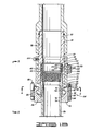
- FIGURES 1A and 1B comprise a sectioned elevation view of a plug container utilizing one form of coupling apparatus of the present invention in place upon a casing of an oil well.
- FIGURE 2 is a plan section view along line 2-2 of Figure 1 showing the orientation of the lower inlet nozzles of the plug container.
- FIGURE 3 is a side elevation view of the latch assembly of the collar taken along line 3-3 of Figure 1.
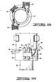
- FIGURE 4 is a plan view of the locking collar pinned in its closed position.
- FIGURE 4A is a plan view of the locking collar pinned in its open position.
- FIGURE 5 is a plan view of the limit ring of the locking collar.
- FIGURE 6 is a plan sectional view along line 6-6 of Figure 1 illustrating the manner in which the upper lips of the locking collar engage the lower surface of the groove of the adjusting nut when the locking collar is in its open position.
- FIGURES 7A and 7B comprise a sectioned elevation view of an alternative embodiment of a plug container of the present invention wherein the housing of the plug container is integral with the body member of the coupling apparatus which is threadably engaged with the adjusting nut of the coupling apparatus.
- FIGURE 8 is a sectional plan view along line 8-8 of Figure 7 showing the orientation of the lower inlet nozzles of the plug container of Figure 7.
- Referring now to the drawings, and particularly to Figure 1, the plug container of the present invention is shown and generally designated by the numeral 10.
- The plug container 10 includes a
housing 12 which has acap 14 threadedly connected to an upper end thereof. Lugs such as 16 are integrally constructed on thecap 14 so that the plug container 10 may be lifted by attaching achain 18 or the like to thelugs 16. - Disposed through a wall of the
housing 12 is aplunger coupling 20 and first and secondlower inlet nozzles 22 and 24 (Figure 2). A release plunger (not shown) is disposed through theplunger coupling 20 for holding a cementing plug (not shown) in a pre-release position above the plunger. A release plunger and a plug are shown in the similar plug container illustrated in Figure 7. - At its lower end the
housing 12 includes aninternal thread 26 which threadedly engages an upperexternal thread 28 of abody 30. - The
body 30 has acylindrical bore 32 disposed in a lower end thereof and has a radially outer threadedlower surface 34. - As shown in Figure 1, a
casing 36 of a well has acasing collar 38 connected to an upper end thereof. Thecasing collar 38 has a radiallyouter surface 40 closely received in thebore 32 of thebody 30. - , A main seal means 42 is disposed in the
bore 32 ofbody 30 for sealing against an annular upward facingend surface 44 ofcasing collar 38. - A
cylindrical adjusting nut 46 has an internally threadedupper end 48 engaged with the lower outer threadedsurface 34 ofbody 30. Adjustingnut 46 further includes anannular groove 50 disposed in a radiallyouter surface 52 thereof. - A
locking collar 54 is connected to the adjustingnut 46 for longitudinal movement therewith relative to thebody 30. - The details of construction of
locking collar 54 are best seen in FIGS. 4 and 4A which are opened and closed views, respectively, of thelocking collar 54.. - The
locking collar 54 includes first and secondarcuate collar portions - First
arcuate collar portion 56 includes afirst end 60 to which are welded upper and lower pivotpin receiving sleeves 62 and 64 (see FIG. 1). - Second
arcuate collar portion 58 includes afirst end 66 to which is welded a middle pivot pin receiving sleeve 68. - A
pivot pin 70 is disposed through the pivotpin receiving sleeves arcuate collar portions - Each of the first and second arcuate collar portions includes an upper radially inward extending
lip 72 and a lower radially inward extendinglip 74. - The upper radially inward extending
lips 72 are received in theannular groove 50 of adjustingnut 46. The lower annular radially inward extendinglips 74 engage alower end 76 ofcasing collar 38. - In order to accurately define the orientations of the various components of the present invention relative to the
casing 36 andcasing collar 38, it is appropriate to define certain orientation terminology. - The
casing 36 andcasing collar 38 may generally be referred to as a cylindrical member. Thecasing collar 38 may be referred to as an enlarged diameter portion of the cylindrical member. Theupper end 44 ofcasing collar 38 may be referred to as either an upward facing end or a longitudinally outward facing end of the enlarged diameter portion of the cylindrical member. Thelower end 76 ofcasing collar 38 may be referred to as either a downward facing annular surface or a longitudinally inward facing annular surface of an enlarged diameter portion of the cylindrical member. - The first and second
arcuate collar portions collar 54 is said to be in a closed position, or which may be spread apart as shown in FIG. 4A wherein thecollar 54 is said to be in the open position. - A latch means generally indicated at 82 is provided for selectively latching the first and
second collar portions collar 54. - The latch means 82 includes an
arcuate latch arm 84 which is pivotally connected adjacent the second end of firstarcuate member 56 by a vertically orientedpivot bolt 86. - As can best be seen in FIGS. 4 and 4A, the
arcuate latch arm 84 is disposed substantially concentrically to thecollar 54 and extends across the space between the second ends 78 and 80 of the first and secondarcuate collar portions - Disposed vertically through the
latch arm 84 is an openlatch position hole 88 and a closed latch position hole (not shown). - When the
collar 54 is in the closed position as shown in FIGS. 3 and 4, the closed positioning hole is located betweenpositioning pin sleeves arcuate collar portion 58 substantially adjacent itssecond end 80 thereof. A quickrelease positioning pin 94 is disposed through thesleeves latch arm 84. - To move the
collar 54 to its open position, it is necessary to remove thepin 94 from thelatch arm 84 and then pivot the first and secondarcuate collar portions open positioning hole 88 oflatch arm 84 is aligned with thesleeves positioning pin 94 is inserted through thesleeves open positioning hole 88 to releasably hold the'collar in its open position. - A
limit plate 96, which can best be seen in FIGS. 1 and 5, is an annular flat plate concentrically disposed about the adjustingnut 46.Limit plate 96 has an orientinghole 98 disposed therethrough through which is received thepivot pin 70 as seen in FIG. 1. Thepivot pin 70 is held in place by anut 100 threaded on the upper end thereof above thelimit plate 96. - As best seen in FIG. 5, the
limit plate 96 includes acutout 102 in a portion thereof substantially opposite the orientinghole 98. - The
cutout 102 defines limit shoulders 104 and 106 which serve to limit the opening movement of thecollar 54 to an extent such that theupper lips 72 of first and secondarcuate collar portions groove 50 of adjustingnut 46. - This limiting of the opening movement of the
collar 54 is achieved by the fact that thepin sleeve 90 attached to thesecond end 80 ofarcuate collar portion 58 abuts thesecond stop shoulder 106, and asimilar pin sleeve 108 attached to thesecond end 78 of firstarcuate collar portion 56 abuts thefirst stop shoulder 104. - Preferably, the
quick release pin 94 is attached to akeeper chain 110 which has itsother end 112 clipped to ahole 114 disposed in thelimit plate 96. - As is best seen in FIG. 6, when the
collar 54 is open to the maximum extent allowed bylimit plate 96, theupper lips 72 of the first and secondarcuate collar portions lower surface 116 defininggroove 50. This prevents thecollar 54 from being removed from the adjustingnut 46 without total disassembly of thecollar 54 by removal of thepivot pin 70. - The main seal 42 is carried by a hydraulically biased seal carrier means 118.
- The seal carrier means 118 includes an
annular carrier ring 120 slidably disposed in thebore 32 ofbody 30. - An annular
outer carrier seal 122 is disposed between thecarrier ring 120 and thebore 32 ofbody 30. - The main seal 42 includes an L-shaped cross-section annular
resilient ring 124 having a first leg 126 engaging bore 32 ofbody 30 and having asecond leg 128 engaging theupper end 44 ofcasing collar 38. L-shapedresilient ring 124 is disposed in a lower radiallyouter end groove 130 ofcarrier ring 120. - Main seal 42 further includes an
anti-extrusion ring 132 engaging both the first andsecond legs 126 and 128 for preventing extrusion of theresilient ring 124 through an annular clearance between theouter surface 40 ofcasing collar 38 and thebore 32 ofbody 30. - The
carrier ring 120 includes an innercylindrical extension 134 extending downward longitudinally beyond main seal means 42 toward thecasing 36.Extension 134 includes a tapered radiallyouter end surface 136 for centeringseal carrier ring 120 relative to theupper end 44 ofcasing collar 38. - An effective sealing diameter of
second leg 128 againstupper end 44 ofcasing collar 38 will be somewhere in the midportion of the annular area of engagement. That effective sealing diameter is less than the inner diameter ofbore 32, so that hydraulic pressure within thebody 30 will act across an annular differential area oncarrier member 120 thus pushing thecarrier member 120 downward and providing a hydraulic bias biasing the main seal 42 against theupper end 44 ofcasing collar 38. - It is also noted, that if a vacuum is present within the casing 36 a downward bias is still provided due to atmospheric pressure acting across the entire area within a circle within the effective sealing diameter of main seal 42. This is because atmospheric pressure will be pushing down upon the entire plug container 10, while there will be no pressure pushing up on the plug container 10 within the area within the effective sealing diameter of main seal 42.
- Referring now to FIGS. 7A-7 , a slightly modified version of the present invention is there illustrated. In the embodiment of FIGS. 7A-7 , the difference of interest is in the fact that the
body 30 and thehousing 12 of FIG. 1 have been constructed as an integral housing-body member 138. - Another feature of the present invention which is best illustrated in FIGS. 7 and 8 is the construction and orientation of the fluid inlet nozzles relative to the
housing body 138. It is noted that the fluid inlet nozzles of the embodiment of FIG. 1 are similarly constructed. - In FIG. 7, the
housing body 138 includes aplug receiving chamber 140 disposed therein. A cylindrically shapedplug 142 is disposed in thechamber 140 and releasably held in a pre-launch position as illustrated by areleasable plunger 144 in a manner which will be familiar to those skilled in the art. An upperfluid inlet nozzle 146 is disposed substantially tangentially through a wall of thehousing body 138 and directed against a side of theplug 142 when theplug 142 is in its pre-launch position as illustrated. - First and second lower
fluid inlet nozzles plug 142 whenplug 142 is in its pre-launch position, and are disposed substantially tangentially through the wall of thehousing body 138. Thelower nozzles housing body 138. - All of the
nozzles - Also, all of the
nozzles housing body 138. - In most prior art plug containers utilizing an upper inlet connection such as 146, the upper inlet nozzle will be located above the plug when the plug is in its pre-launch position and the upper inlet nozzle is typically oriented radially relative to the housing.
- By orienting the
upper inlet nozzle 146 tangentially, and directing it against the side of theplug 142, a twisting force is imposed on theplug 142 which is believed to help initiate movement of theplug 142 within thehousing body 138 so that it may be reliably displaced therefrom when theplunger 144 is released. - The tangential orientation of the lower
fluid inlet nozzles plug 142 creates a swirling vortex type flow which is believed to further aid in the displacement of theplug 142 by imposing a rotational force thereon and also creating a downward sucking force due to the vortex action. - The manner of use of the present invention is generally as follows.
- Referring to FIG. 1 as an example, the
housing 12 is assembled to thebody 30. The adjustingnut 46 is made up on thebody 30. The first and secondarcuate collar portions nut 46 with theupper lips 70 in thegroove 50 and the lockingcollar 54 is then assembled by placing thepivot pin 70 in place through the first and secondarcuate collar portions limit plate 96. The lockingcollar 54 is then latched in its open position as shown in FIG. 4A. Suitable cementing plugs such as 142 are placed in thehousing 12 and thecap 14 is placed on thehousing 12. - The plug container 10 is then lowered over the
casing collar 38 so that thecasing collar 38 is received within thebore 32 ofbody 30 and engages the main seal 42. - The
latch pin 94 is then removed and the lockingcollar 54 is moved to its closed position and latched in place therein with thelatch pin 94 so that thelower lips 74 extend below and engage thelower end 76 ofcasing collar 38. - The initial compression of main seal 42 may then be adjusted by increasing the threaded connection between
threads nut 46 inbody 30. - Additional sealing is provided once hydraulic pressure is present within the
casing 36 due to the hydraulic biasing of seal carrier means 118. - Thus it is seen that the apparatus of the present invention readily achieves the ends and advantages mentioned as well as those inherent therein. While certain preferred embodiments of the present invention has been illustrated for the purposes of this disclosure, numerous changes in the arrangement and construction of parts may be made by those skilled in the art.
Claims (9)
Priority Applications (1)
| Application Number | Priority Date | Filing Date | Title |
|---|---|---|---|
| MYPI87001705A MY102360A (en) | 1982-05-04 | 1987-09-17 | Coupling device. |
Applications Claiming Priority (2)
| Application Number | Priority Date | Filing Date | Title |
|---|---|---|---|
| US06/374,869 US4524998A (en) | 1982-05-04 | 1982-05-04 | Tubular connecting device |
| US374869 | 1982-05-04 |
Publications (3)
| Publication Number | Publication Date |
|---|---|
| EP0093561A2 true EP0093561A2 (en) | 1983-11-09 |
| EP0093561A3 EP0093561A3 (en) | 1985-01-23 |
| EP0093561B1 EP0093561B1 (en) | 1987-07-08 |
Family
ID=23478520
Family Applications (1)
| Application Number | Title | Priority Date | Filing Date |
|---|---|---|---|
| EP83302336A Expired EP0093561B1 (en) | 1982-05-04 | 1983-04-25 | Coupling device |
Country Status (9)
| Country | Link |
|---|---|
| US (2) | US4524998A (en) |
| EP (1) | EP0093561B1 (en) |
| AU (1) | AU563357B2 (en) |
| BR (1) | BR8302270A (en) |
| CA (1) | CA1208676A (en) |
| DE (1) | DE3372392D1 (en) |
| ES (1) | ES8500378A1 (en) |
| MY (1) | MY102360A (en) |
| SG (1) | SG103087G (en) |
Cited By (3)
| Publication number | Priority date | Publication date | Assignee | Title |
|---|---|---|---|---|
| US5441310A (en) * | 1994-03-04 | 1995-08-15 | Fmc Corporation | Cement head quick connector |
| WO2002037015A1 (en) * | 2000-10-16 | 2002-05-10 | Weatherford/Lamb, Inc. | Coupling apparatus |
| GB2526436A (en) * | 2014-05-21 | 2015-11-25 | Vetco Gray Scandinavia As | Hydraulic tool |
Families Citing this family (89)
| Publication number | Priority date | Publication date | Assignee | Title |
|---|---|---|---|---|
| US4524998A (en) * | 1982-05-04 | 1985-06-25 | Halliburton Company | Tubular connecting device |
| US4574882A (en) * | 1984-10-29 | 1986-03-11 | Halliburton Company | Plug container |
| AU575244B2 (en) * | 1985-03-08 | 1988-07-21 | Halliburton Company | Coupling for cement plug container |
| DE3519725A1 (en) * | 1985-06-01 | 1986-12-04 | Merck Patent Gmbh | CHROMATOGRAPHIC COLUMN |
| US4718495A (en) * | 1986-05-08 | 1988-01-12 | Halliburton Company | Surface packer and method for using the same |
| FR2636716B1 (en) * | 1988-09-21 | 1990-12-07 | Staubli Sa Ets | DEVICE FOR COUPLING ELEMENT HOLDER PLATES OF MULTIPLE FITTINGS |
| US4917184A (en) * | 1989-02-14 | 1990-04-17 | Halliburton Company | Cement head and plug |
| FR2645616A1 (en) * | 1989-04-07 | 1990-10-12 | Saint Hubert Ind Laitiere | Collar for fixing a hose made from a flexible material to a rigid pipe |
| US5348351A (en) * | 1990-12-18 | 1994-09-20 | Lafleur Petroleum Services, Inc. | Coupling apparatus |
| US5152554A (en) * | 1990-12-18 | 1992-10-06 | Lafleur Petroleum Services, Inc. | Coupling apparatus |
| US5152556A (en) * | 1990-12-24 | 1992-10-06 | Kaiser Aerospace And Electronics Corporation | High temperature tubing joint with threaded, split collar |
| US5131693A (en) * | 1991-04-12 | 1992-07-21 | Pacific Roller Die Co., Inc. | Pipe coupling method |
| US5413171A (en) * | 1992-05-01 | 1995-05-09 | Downhole Systems, Inc. | Latching and sealing assembly |
| US7228901B2 (en) | 1994-10-14 | 2007-06-12 | Weatherford/Lamb, Inc. | Method and apparatus for cementing drill strings in place for one pass drilling and completion of oil and gas wells |
| US7040420B2 (en) | 1994-10-14 | 2006-05-09 | Weatherford/Lamb, Inc. | Methods and apparatus for cementing drill strings in place for one pass drilling and completion of oil and gas wells |
| US5501280A (en) * | 1994-10-27 | 1996-03-26 | Halliburton Company | Casing filling and circulating apparatus and method |
| US5603152A (en) * | 1994-12-19 | 1997-02-18 | General Motors Corporation | Method for manufacturing a two block line connector |
| US5605358A (en) * | 1995-10-13 | 1997-02-25 | Cajon Company | Tube coupling |
| US5950724A (en) * | 1996-09-04 | 1999-09-14 | Giebeler; James F. | Lifting top drive cement head |
| US7509722B2 (en) | 1997-09-02 | 2009-03-31 | Weatherford/Lamb, Inc. | Positioning and spinning device |
| US6536520B1 (en) | 2000-04-17 | 2003-03-25 | Weatherford/Lamb, Inc. | Top drive casing system |
| US6742596B2 (en) | 2001-05-17 | 2004-06-01 | Weatherford/Lamb, Inc. | Apparatus and methods for tubular makeup interlock |
| US5971079A (en) * | 1997-09-05 | 1999-10-26 | Mullins; Albert Augustus | Casing filling and circulating apparatus |
| US6675889B1 (en) | 1998-05-11 | 2004-01-13 | Offshore Energy Services, Inc. | Tubular filling system |
| US6390190B2 (en) | 1998-05-11 | 2002-05-21 | Offshore Energy Services, Inc. | Tubular filling system |
| US6244349B1 (en) * | 1998-05-14 | 2001-06-12 | Halliburton Energy Services, Inc. | Circulating nipple and method for setting well casing |
| US6199914B1 (en) | 1998-06-09 | 2001-03-13 | Duhn Oil Tool, Inc. | Drilling quick connectors |
| GB9815809D0 (en) | 1998-07-22 | 1998-09-16 | Appleton Robert P | Casing running tool |
| GB2340858A (en) * | 1998-08-24 | 2000-03-01 | Weatherford Lamb | Methods and apparatus for facilitating the connection of tubulars using a top drive |
| GB2340857A (en) | 1998-08-24 | 2000-03-01 | Weatherford Lamb | An apparatus for facilitating the connection of tubulars and alignment with a top drive |
| GB2340859A (en) | 1998-08-24 | 2000-03-01 | Weatherford Lamb | Method and apparatus for facilitating the connection of tubulars using a top drive |
| US6779599B2 (en) | 1998-09-25 | 2004-08-24 | Offshore Energy Services, Inc. | Tubular filling system |
| US7188687B2 (en) | 1998-12-22 | 2007-03-13 | Weatherford/Lamb, Inc. | Downhole filter |
| GB2345074A (en) | 1998-12-24 | 2000-06-28 | Weatherford Lamb | Floating joint to facilitate the connection of tubulars using a top drive |
| US6302140B1 (en) | 1999-01-28 | 2001-10-16 | Halliburton Energy Services, Inc. | Cementing head valve manifold |
| US6173777B1 (en) | 1999-02-09 | 2001-01-16 | Albert Augustus Mullins | Single valve for a casing filling and circulating apparatus |
| US7311148B2 (en) | 1999-02-25 | 2007-12-25 | Weatherford/Lamb, Inc. | Methods and apparatus for wellbore construction and completion |
| AU776634B2 (en) | 1999-12-22 | 2004-09-16 | Weatherford Technology Holdings, Llc | Drilling bit for drilling while running casing |
| US7334650B2 (en) | 2000-04-13 | 2008-02-26 | Weatherford/Lamb, Inc. | Apparatus and methods for drilling a wellbore using casing |
| US7325610B2 (en) | 2000-04-17 | 2008-02-05 | Weatherford/Lamb, Inc. | Methods and apparatus for handling and drilling with tubulars or casing |
| US6811189B1 (en) * | 2000-10-04 | 2004-11-02 | Grant Prideco, L.P. | Corrosion seal for threaded connections |
| KR100398790B1 (en) * | 2001-05-03 | 2003-09-19 | 윤종경 | a support belt of flange coupling tube |
| US7055870B2 (en) * | 2001-07-12 | 2006-06-06 | Hayes Jr Frank F | Molded flare assembly |
| US6994176B2 (en) | 2002-07-29 | 2006-02-07 | Weatherford/Lamb, Inc. | Adjustable rotating guides for spider or elevator |
| US6764109B2 (en) * | 2002-07-31 | 2004-07-20 | H. Gary Richardson | Hammer union and seal therefor |
| US7730965B2 (en) * | 2002-12-13 | 2010-06-08 | Weatherford/Lamb, Inc. | Retractable joint and cementing shoe for use in completing a wellbore |
| US7303022B2 (en) | 2002-10-11 | 2007-12-04 | Weatherford/Lamb, Inc. | Wired casing |
| US6899358B2 (en) | 2002-11-13 | 2005-05-31 | H. Gary Richardson | Hammer union and seal therefor |
| USRE42877E1 (en) | 2003-02-07 | 2011-11-01 | Weatherford/Lamb, Inc. | Methods and apparatus for wellbore construction and completion |
| US7413020B2 (en) | 2003-03-05 | 2008-08-19 | Weatherford/Lamb, Inc. | Full bore lined wellbores |
| US7874352B2 (en) | 2003-03-05 | 2011-01-25 | Weatherford/Lamb, Inc. | Apparatus for gripping a tubular on a drilling rig |
| CA2517978C (en) | 2003-03-05 | 2009-07-14 | Weatherford/Lamb, Inc. | Drilling with casing latch |
| CA2677247C (en) | 2003-03-05 | 2012-09-25 | Weatherford/Lamb, Inc. | Casing running and drilling system |
| CA2520072C (en) | 2003-04-04 | 2010-02-16 | Weatherford/Lamb, Inc. | Method and apparatus for handling wellbore tubulars |
| US6978844B2 (en) * | 2003-07-03 | 2005-12-27 | Lafleur Petroleum Services, Inc. | Filling and circulating apparatus for subsurface exploration |
| US7264067B2 (en) | 2003-10-03 | 2007-09-04 | Weatherford/Lamb, Inc. | Method of drilling and completing multiple wellbores inside a single caisson |
| US7284617B2 (en) * | 2004-05-20 | 2007-10-23 | Weatherford/Lamb, Inc. | Casing running head |
| GB2415445B (en) * | 2004-06-22 | 2008-12-17 | Schlumberger Holdings | Logging plug with high integrity internal seal |
| DE602005006198T2 (en) | 2004-07-20 | 2009-07-09 | Weatherford/Lamb, Inc., Houston | Upper drive for connecting casing pipes |
| CA2514136C (en) | 2004-07-30 | 2011-09-13 | Weatherford/Lamb, Inc. | Apparatus and methods of setting and retrieving casing with drilling latch and bottom hole assembly |
| US7694744B2 (en) | 2005-01-12 | 2010-04-13 | Weatherford/Lamb, Inc. | One-position fill-up and circulating tool and method |
| CA2533115C (en) | 2005-01-18 | 2010-06-08 | Weatherford/Lamb, Inc. | Top drive torque booster |
| CA2538196C (en) | 2005-02-28 | 2011-10-11 | Weatherford/Lamb, Inc. | Deep water drilling with casing |
| US7392840B2 (en) * | 2005-12-20 | 2008-07-01 | Halliburton Energy Services, Inc. | Method and means to seal the casing-by-casing annulus at the surface for reverse circulation cement jobs |
| GB2437647B (en) | 2006-04-27 | 2011-02-09 | Weatherford Lamb | Torque sub for use with top drive |
| CA2651966C (en) | 2006-05-12 | 2011-08-23 | Weatherford/Lamb, Inc. | Stage cementing methods used in casing while drilling |
| US8276689B2 (en) | 2006-05-22 | 2012-10-02 | Weatherford/Lamb, Inc. | Methods and apparatus for drilling with casing |
| US7882902B2 (en) | 2006-11-17 | 2011-02-08 | Weatherford/Lamb, Inc. | Top drive interlock |
| US20090261575A1 (en) * | 2008-04-22 | 2009-10-22 | Halliburton Energy Services Inc. | Adjustable Length Discharge Joint for High Pressure Applications |
| WO2009132259A2 (en) * | 2008-04-24 | 2009-10-29 | National Oilwell Varco, L.P. | Torque member for threaded connections |
| US8381808B2 (en) * | 2008-10-29 | 2013-02-26 | Halliburton Energy Services, Inc. | Cement head |
| CN103124829B (en) | 2010-07-07 | 2015-08-26 | 国民油井华高有限公司 | The screw thread coupling that moment of torsion increases |
| US8540031B2 (en) * | 2010-12-29 | 2013-09-24 | Michael Rimi | Encapsulating device |
| US9791076B2 (en) * | 2010-12-31 | 2017-10-17 | Eaton Corporation | Swage visual indicator for fluid coupling |
| GB201112163D0 (en) * | 2011-07-15 | 2011-08-31 | Rolls Royce Plc | Tip clearance control for turbine blades |
| EP2941532A4 (en) | 2013-01-04 | 2017-04-19 | Carbo Ceramics Inc. | Electrically conductive proppant and methods for detecting, locating and characterizing the electrically conductive proppant |
| US9434875B1 (en) | 2014-12-16 | 2016-09-06 | Carbo Ceramics Inc. | Electrically-conductive proppant and methods for making and using same |
| US11008505B2 (en) | 2013-01-04 | 2021-05-18 | Carbo Ceramics Inc. | Electrically conductive proppant |
| US9638362B2 (en) | 2014-05-02 | 2017-05-02 | National Oilwell Varco, L.P. | Threaded connections with an adjustable secondary shoulder |
| US9551210B2 (en) | 2014-08-15 | 2017-01-24 | Carbo Ceramics Inc. | Systems and methods for removal of electromagnetic dispersion and attenuation for imaging of proppant in an induced fracture |
| NL1041552B1 (en) * | 2015-10-30 | 2017-05-24 | Wavin Bv | A coupling system and a method for coupling two pipe ends. |
| US10480696B2 (en) * | 2015-12-01 | 2019-11-19 | Forum Us, Inc. | Locking collar quick union connection |
| US10041308B2 (en) * | 2015-12-09 | 2018-08-07 | Nabors Drilling Technologies Usa, Inc. | Oilfield tubular connection system and method |
| NL1041958B1 (en) | 2016-06-29 | 2018-01-05 | Wavin Bv | Press fitting device |
| US10605051B2 (en) | 2017-06-22 | 2020-03-31 | Unseated Tools LLC | Method of pumping fluids down a wellbore |
| US10605017B2 (en) | 2017-06-22 | 2020-03-31 | Unseated Tools LLC | Unseating tool for downhole standing valve |
| USD882641S1 (en) | 2017-07-25 | 2020-04-28 | Unseated Tools LLC | Two-pronged latch for downhole tool |
| US11959339B2 (en) * | 2020-12-17 | 2024-04-16 | McClinton Energy Group, LLC | Cementing adapter systems and methods |
| CN117266783A (en) * | 2023-10-27 | 2023-12-22 | 中国石油化工股份有限公司 | A non-welded quick-installation casing cement head |
Family Cites Families (29)
| Publication number | Priority date | Publication date | Assignee | Title |
|---|---|---|---|---|
| US1016620A (en) * | 1910-07-06 | 1912-02-06 | John Gapp | Pipe-coupling. |
| US1098620A (en) * | 1913-02-01 | 1914-06-02 | Henry Gillar | Hose connection. |
| US1509906A (en) * | 1922-07-17 | 1924-09-30 | Sawtelle Gilbert Goss | Wire-line lubricator |
| US1662311A (en) * | 1923-04-04 | 1928-03-13 | Leland S Hamer | Well-capping device |
| US1629022A (en) * | 1924-04-22 | 1927-05-17 | Herbert A Davis | Cementing head |
| US1866726A (en) * | 1929-09-20 | 1932-07-12 | Grant John | Casing head |
| CH148383A (en) * | 1930-07-14 | 1931-07-15 | Burkhardt Hans | Coupling for hose and pipelines. |
| US2223388A (en) * | 1939-10-28 | 1940-12-03 | Oil Equipment Engineering Corp | Cementing head |
| US2498915A (en) * | 1948-02-02 | 1950-02-28 | Nels A Espegren | Gasket unit for swivel connections |
| US2620037A (en) * | 1951-07-02 | 1952-12-02 | Halliburton Oil Well Cementing | Cementing head |
| DE1149069B (en) * | 1957-10-31 | 1963-05-22 | Siemens Ag | Coupling device for tubular lines |
| US3113792A (en) * | 1960-02-16 | 1963-12-10 | Fmc Corp | Pipe union with separable flange for nut |
| US3291442A (en) * | 1964-07-27 | 1966-12-13 | Stile Craft Mfg Inc | Gas or vacuum-operated couplings |
| US3545542A (en) * | 1968-06-10 | 1970-12-08 | Byron Jackson Inc | Cementing plug launching apparatus |
| US3616850A (en) * | 1970-04-20 | 1971-11-02 | Byron Jackson Inc | Cementing plug launching mandrel |
| US3863716A (en) * | 1974-04-05 | 1975-02-04 | Halliburton Co | Cementing plug release assist apparatus |
| US3915226A (en) * | 1974-10-11 | 1975-10-28 | Halliburton Co | Double collet release mechanism |
| US4061366A (en) * | 1975-10-01 | 1977-12-06 | Affa Stephen N | Connector |
| DE2553189C3 (en) * | 1975-11-27 | 1978-05-18 | Karl Ing.(Grad.) 4040 Neuss Weinhold | Device for the detachable fastening of hose or pipe ends |
| US4209270A (en) * | 1977-04-18 | 1980-06-24 | Hydrotech International, Inc. | Pipe connector apparatus and method |
| US4124233A (en) * | 1977-05-04 | 1978-11-07 | Vetco, Inc. | Rigid pipe connector with lock ring and method of making the same |
| US4209193A (en) * | 1977-05-17 | 1980-06-24 | Vetco, Inc. | Rigid connector for large diameter pipe |
| US4219226A (en) * | 1978-07-27 | 1980-08-26 | Westinghouse Electric Corp. | Cylinder joint |
| US4246967A (en) * | 1979-07-26 | 1981-01-27 | The Dow Chemical Company | Cementing head apparatus and method of operation |
| US4278278A (en) * | 1979-08-30 | 1981-07-14 | W-K-M Wellhead Systems, Inc. | Means for tensioning tubing in a wellhead assembly |
| US4290482A (en) * | 1980-04-29 | 1981-09-22 | Halliburton Company | Plug container |
| US4522430A (en) * | 1981-02-27 | 1985-06-11 | Halliburton Company | Quick connect coupler |
| US4453745A (en) * | 1981-08-17 | 1984-06-12 | Nelson Norman A | Lockdown mechanism for wellhead connector |
| US4524998A (en) * | 1982-05-04 | 1985-06-25 | Halliburton Company | Tubular connecting device |
-
1982
- 1982-05-04 US US06/374,869 patent/US4524998A/en not_active Expired - Lifetime
-
1983
- 1983-04-20 CA CA000426214A patent/CA1208676A/en not_active Expired
- 1983-04-25 EP EP83302336A patent/EP0093561B1/en not_active Expired
- 1983-04-25 DE DE8383302336T patent/DE3372392D1/en not_active Expired
- 1983-05-02 AU AU14145/83A patent/AU563357B2/en not_active Ceased
- 1983-05-03 ES ES522041A patent/ES8500378A1/en not_active Expired
- 1983-05-03 BR BR8302270A patent/BR8302270A/en unknown
-
1985
- 1985-03-08 US US06/709,628 patent/US4613161A/en not_active Expired - Lifetime
-
1987
- 1987-09-17 MY MYPI87001705A patent/MY102360A/en unknown
- 1987-11-25 SG SG1030/87A patent/SG103087G/en unknown
Cited By (7)
| Publication number | Priority date | Publication date | Assignee | Title |
|---|---|---|---|---|
| US5441310A (en) * | 1994-03-04 | 1995-08-15 | Fmc Corporation | Cement head quick connector |
| WO2002037015A1 (en) * | 2000-10-16 | 2002-05-10 | Weatherford/Lamb, Inc. | Coupling apparatus |
| US7147254B2 (en) | 2000-10-16 | 2006-12-12 | Weatherford/Lamb, Inc. | Coupling apparatus |
| US7384077B2 (en) | 2000-10-16 | 2008-06-10 | Weatherford/Lamb, Inc. | Coupling apparatus |
| US7758087B2 (en) | 2000-10-16 | 2010-07-20 | Weatherford/Lamb, Inc. | Coupling apparatus |
| GB2526436A (en) * | 2014-05-21 | 2015-11-25 | Vetco Gray Scandinavia As | Hydraulic tool |
| GB2526436B (en) * | 2014-05-21 | 2017-09-13 | Vetco Gray Scandinavia As | Hydraulic tool |
Also Published As
| Publication number | Publication date |
|---|---|
| BR8302270A (en) | 1984-01-03 |
| MY102360A (en) | 1992-06-17 |
| ES522041A0 (en) | 1984-10-01 |
| SG103087G (en) | 1988-06-03 |
| EP0093561B1 (en) | 1987-07-08 |
| DE3372392D1 (en) | 1987-08-13 |
| US4524998A (en) | 1985-06-25 |
| ES8500378A1 (en) | 1984-10-01 |
| US4613161A (en) | 1986-09-23 |
| CA1208676A (en) | 1986-07-29 |
| AU1414583A (en) | 1983-11-10 |
| AU563357B2 (en) | 1987-07-09 |
| EP0093561A3 (en) | 1985-01-23 |
Similar Documents
| Publication | Publication Date | Title |
|---|---|---|
| EP0093561B1 (en) | Coupling device | |
| US6517125B2 (en) | Cementing head | |
| US4624483A (en) | Quick connect coupler | |
| US4522430A (en) | Quick connect coupler | |
| CA2142375C (en) | Cement head quick connector | |
| DE3784382T2 (en) | VALVE FOR LEAK TEST TESTING. | |
| CA1086223A (en) | Split-ring riser latch | |
| US5236035A (en) | Swivel cementing head with manifold assembly | |
| CA1201379A (en) | Ball actuated releasable coupling | |
| US6470971B1 (en) | Tubing head control and pressure monitor device | |
| DE3855150T2 (en) | Sealing arrangement for submarine casing hanger | |
| US3915226A (en) | Double collet release mechanism | |
| US5535822A (en) | Apparatus for retrieving whipstock | |
| CA1187407A (en) | Hydraulic setting tool with flapper valve | |
| US5054833A (en) | Releasable overshot | |
| US4237979A (en) | Valve for hydraulic setting packer setting tool and method of setting a hydraulically settable packer therewith | |
| US4773478A (en) | Hydraulic setting tool | |
| US3036810A (en) | Subsurface valve apparatus | |
| US4436149A (en) | Hydraulic setting tool | |
| US4040649A (en) | Oil well tool with packing means | |
| US4018275A (en) | Anchoring device for well tools | |
| CN114427438A (en) | Multifunctional pressure testing device for shaft | |
| US1961762A (en) | Rotary drill pipe collar or coupling with sealed joints | |
| EP0204823A1 (en) | Side pocket mandrel. | |
| US9970259B2 (en) | Dump valve arrangement for fracturing tool set |
Legal Events
| Date | Code | Title | Description |
|---|---|---|---|
| PUAI | Public reference made under article 153(3) epc to a published international application that has entered the european phase |
Free format text: ORIGINAL CODE: 0009012 |
|
| AK | Designated contracting states |
Designated state(s): DE FR GB IT NL |
|
| PUAL | Search report despatched |
Free format text: ORIGINAL CODE: 0009013 |
|
| AK | Designated contracting states |
Designated state(s): DE FR GB IT NL |
|
| 17P | Request for examination filed |
Effective date: 19850306 |
|
| 17Q | First examination report despatched |
Effective date: 19860204 |
|
| ITF | It: translation for a ep patent filed | ||
| GRAA | (expected) grant |
Free format text: ORIGINAL CODE: 0009210 |
|
| AK | Designated contracting states |
Kind code of ref document: B1 Designated state(s): DE FR GB IT NL |
|
| REF | Corresponds to: |
Ref document number: 3372392 Country of ref document: DE Date of ref document: 19870813 |
|
| ET | Fr: translation filed | ||
| PLBE | No opposition filed within time limit |
Free format text: ORIGINAL CODE: 0009261 |
|
| STAA | Information on the status of an ep patent application or granted ep patent |
Free format text: STATUS: NO OPPOSITION FILED WITHIN TIME LIMIT |
|
| 26N | No opposition filed | ||
| ITTA | It: last paid annual fee | ||
| REG | Reference to a national code |
Ref country code: GB Ref legal event code: IF02 |
|
| PGFP | Annual fee paid to national office [announced via postgrant information from national office to epo] |
Ref country code: FR Payment date: 20020410 Year of fee payment: 20 |
|
| PGFP | Annual fee paid to national office [announced via postgrant information from national office to epo] |
Ref country code: GB Payment date: 20020424 Year of fee payment: 20 |
|
| PGFP | Annual fee paid to national office [announced via postgrant information from national office to epo] |
Ref country code: NL Payment date: 20020426 Year of fee payment: 20 |
|
| PGFP | Annual fee paid to national office [announced via postgrant information from national office to epo] |
Ref country code: DE Payment date: 20020502 Year of fee payment: 20 |
|
| PG25 | Lapsed in a contracting state [announced via postgrant information from national office to epo] |
Ref country code: GB Free format text: LAPSE BECAUSE OF EXPIRATION OF PROTECTION Effective date: 20030424 |
|
| PG25 | Lapsed in a contracting state [announced via postgrant information from national office to epo] |
Ref country code: NL Free format text: LAPSE BECAUSE OF EXPIRATION OF PROTECTION Effective date: 20030425 |
|
| REG | Reference to a national code |
Ref country code: GB Ref legal event code: PE20 |
|
| NLV7 | Nl: ceased due to reaching the maximum lifetime of a patent |
Effective date: 20030425 |