EP0093537A2 - Optisches Abbildungssystem - Google Patents
Optisches Abbildungssystem Download PDFInfo
- Publication number
- EP0093537A2 EP0093537A2 EP83302201A EP83302201A EP0093537A2 EP 0093537 A2 EP0093537 A2 EP 0093537A2 EP 83302201 A EP83302201 A EP 83302201A EP 83302201 A EP83302201 A EP 83302201A EP 0093537 A2 EP0093537 A2 EP 0093537A2
- Authority
- EP
- European Patent Office
- Prior art keywords
- document
- imaging
- photoreceptor
- velocity
- platen
- Prior art date
- Legal status (The legal status is an assumption and is not a legal conclusion. Google has not performed a legal analysis and makes no representation as to the accuracy of the status listed.)
- Granted
Links
Images


Classifications
-
- G—PHYSICS
- G03—PHOTOGRAPHY; CINEMATOGRAPHY; ANALOGOUS TECHNIQUES USING WAVES OTHER THAN OPTICAL WAVES; ELECTROGRAPHY; HOLOGRAPHY
- G03B—APPARATUS OR ARRANGEMENTS FOR TAKING PHOTOGRAPHS OR FOR PROJECTING OR VIEWING THEM; APPARATUS OR ARRANGEMENTS EMPLOYING ANALOGOUS TECHNIQUES USING WAVES OTHER THAN OPTICAL WAVES; ACCESSORIES THEREFOR
- G03B27/00—Photographic printing apparatus
- G03B27/32—Projection printing apparatus, e.g. enlarger, copying camera
- G03B27/52—Details
- G03B27/522—Projection optics
- G03B27/525—Projection optics for slit exposure
- G03B27/526—Projection optics for slit exposure in which the projection optics move
Definitions
- the present invention relates to an imaging system which utilizes a linear lens array in an optical system to transmit an image of a document at an object plane to an image plane at a reduction or enlargement value. More particularly, the invention relates to an imaging system which utilizes a moving document, a moving imaging assembly and a moving photoreceptor belt in a predetermined set of velocity relationships.
- Each of these prior art copiers uses a single gradient index lens array to transmit images at a magnification of 1:1.
- Each of these imaging systems utilizes a fixed lens system, scanning being accomplished by moving the document past the lens in conjunction with a similar motion of a photoconductive imaging plane.
- a third system is known wherein the document, photoconductive imaging plane and linear lens array all move at speeds bearing a certain relationship to each other.
- This type of system as disclosed in Japanese Publications 53-97436, 55-52074 and U. S. Patent 3,754,822 have the desirable characteristics of compactness coupled with increases in copy rate for a given process speed.
- All of the above-disclosed systems are related to imaging systems which transrr it images at unity (1X) magnification.
- An imaging system using a linear lens array in a multi-magnification mode system is disclosed in U. S. Patent 4,331-380.
- various reproduction systems are disclosed which utilize a gradient index lens array as the imaging device.
- One embodiment jiscloses a lens assembly consisting of a 1X array coupled with a reduction/er argement lens array, the latter constructed according to the principles di-closed in said application.
- This system utilizes a moving platen and fixed lens array, the platen to photoreceptor speed changing during magnificatic changes to maintain proper image exposure at the photoreceptf
- the present invention is directed to modification of this system whei in the document, photoreceptor and lens array assembly are all moving in uniquenly defined relationships during a reduction or enlargement mode of opei ation. More specifically, the invention is directed to an imaging system for projecting an erect image of a document lying in an object plane onto a photo eceptor lying in an image plane parallel to said object plane at a plurality of agnifications other than unity.
- a i additional feature of the above system is the added advantage of enabling be scanning system in a precession scanning mode in which the scanning of a cocument is accomplished at a faster rate than the process speed so as to caus the image at the image plane to be precessed, or moved, along the image pl ne in a direction opposite to the movement of the image plane.
- a major advamtage of any precession system is that it can reduce throughput time by using the process distance gained during the precession activity to accomplish a specific time consuming activity such as placing a new document on the platen and/or returning the scan system to a start-of-scan position.
- Figure 1 illustrates, in side view schematic, an optical system which utilizes a moving linear gradient index lens array to project a reduced image of a document moving through a scanning zone onto the surface of a moving photoreceptor.
- the system is shown at a start-of-scan position.
- a document 12 is shown, on a platen 14 which is movable along a horizontal plane during scanning operation by operation of a suitable drive means such as reversible drive motor 16.
- a suitable drive means such as reversible drive motor 16.
- the movement during scanning is in the direction indicated by the solid arrow.
- a flat portion 17 of an endless loop photoreceptor belt lies in a plane which is parallel to that traversed by the platen.
- Belt 17 is continually driven by a suitable drive means such as motor 18, in the direction shown by the solid arrow during a scanning operation.
- a reduction gradient index array 20 is positioned, in generally perpendicular orientation, between platen 14 and belt 17. Design details for construction of lens array 20 are provided in U. S. Patent 4,331,380. Attached to array 20 is an elongated lamp/reflector combination 22 which is adapted to provide a narrow, longitudinally extending, illumination strip along the bottom of platen 14. Lens array 20 and lamp/reflector combination 22 together form an imaging assembly 24. Assembly 24 is moved during scanning, in the direction shown by the arrow, by any suitable drive means such as reversible motor 26.
- the scanning rates of movement, or velocities, of the various moving components during a document scan operation are identified as follows:
- the general principle applicable to any document imaging system is that, to obtain properly focused, blur-free imaging, the velocity of the image being transmitted to the photoreceptor must be synchronized to the velocity of the photoreceptor.
- this principle requires consideration of the object, image and photoreceptor velocities with regard to the imaging assembly velocity.
- Equation (1) provides the general conditions for determining the necessary velocity relationships which will enable the Figure 1 system.
- the exposure velocity is v + v
- the image width at the photoreceptor is mw
- the exposure time is
- the sum of the platen displacement and the lens displacement equals the document width w for any value of imaging assembly velocity v", photoreceptor velocity v or platen velocity v'. Also, the imac ng assembly displacement plus the photoreceptor displacement equals the imace width mw for any value of v, v' or v".
- Figure 2 also illustrates an additional advantage of the present invention.
- platen 14 and assembly 24 can easily be driven by their respective motors 16, 26 back to the start-of-scan positions.
- the next image can thus be formed on photoreceptor 17 with little or no inter-image separation thereby increasing process throughput.
- the time t can also be used to replace document 12 with another document.
- a second desirable lens-platen velocity relationship is to drive the lens at one half the platen speed; i. e. make Solving equation (1) for this condition:
- Photoreceptor 17 moves at a velocity determined by equation (6) to point A" for a displacement z'. The sum of the lens displacement y' plus the photoreceptor displacement z' equals mw (.707w).
- the velocities and displacements are to be determined for enlargement modes of operation using the principles set forth above.
- the image width at the photoreceptor is mw and the exposure time is Then, the necessary platen, imaging assembly and photoreceptor displacements are defined as follows: Platen displacement equals zero; from equation (3), imaging assembly displacement equals w and, from equation (4) photoreceptor displacement equals (m - 1) w.
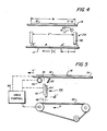
- FIG. 4 there is shown a scanning system in which document 12 of width w is placed on stationary platen 14.
- a photoreceptor belt 17 is continually driven in the direction shown.
- Imaging assembly 24 is moved, during scanning, in a direction determined by the magnification factor m.
- FIG. 4 shows the lens and photoreceptor at the beginning and end-of-scan positions for a .707 reduction.
- imaging assembly 24 is at the solid line position projecting the r ght hand edge of the document onto point A of belt 17.
- the assembly 24 displacement value y" is equal to w.
- Point A on the photoreceptor is displaced a distance of (m - 1)
- either the imaging assembly or the photoreceptor must reverse direction. Since it is usually quite difficult to provide for a 2-way belt travel, the direction of assembly 24 would be reversed and the assembly would be moved at a velocity determined by Eq ration (7). Thus, the start-and-end-of-scan position shown in Figure 4 will be re versed.
- Figures 5 and 6 show an optical system which employs a simple drive means for enabling operation in a full range of ma nifications including unity.
- a sca system wherein a conventional 1X lens array is used in conjunction with a reduction/enlargement lens array designed for a particular magnification wi ich, in the system disclosed, is a .707X reduction.
- a document 32 is placed on platen 34 which is adapted to move at a velocity v'.
- a constantly changing exposure strip 36 is brightly illuminated by apertured lamp 38 acting in combination with a reflector 40.
- a gradient index lens array assembly movable at velocity v" includes gradient index lens array 42, which transmits an image at unity magnification, and a reduction lens array 44 connected to array 42.
- Shutter 46 is adapted to place the appropriate lens array into an optically transmitting position.
- Lamp 38, reflector 40, and lens arrays 42, 44 together form an imaging assembly 48.
- a document image is transmitted to photoreceptor belt 49 moving at a velocity v in the indicated direction.
- drive control system 50 is adapted to vary these velocity relationships upon selection of a particular magnification mode.
- Figure 6 shows a preferred embodiment o drive system 50 (shown in block form in Figure 2).
- This drive system trar, lates an initial motion imparted to the photoreceptor belt 49 into the required motions of platen 34, imaging assembly 48 by using a combination of pulleys, drive cables and clutches.
- the system components are shown in a start-of-scan position, the imaging assembly scanning dire; :ion being from left to right, and platen and photoreceptor movement from ricat to left.
- Photoreceptor belt 49 is continually driven in a counterclockwise direction at a velocity v by means of motor 60 drivinc shaft 61 via belt/pulley assembly 62.
- Belt 49 is entrained about drive pulley 64a which is driven by shaft 61.
- the belt is driven in the counterclockwise direction being maintained in a flat exposure condition by entraining along roller pulleys 64a, 64b, 64c.
- the motion of drive pulley 63 is transmitted to .ackshaft 65 via timing belt 66 entrained about pulley 63 and pulley 67.
- belt 66 motion is transmitted in the same direction as platen 34 by energizing clutch 68.
- This action transmits the motion of jackshaft 65 to platen drive shaft 70 via belt 72 driving pulley 74.
- Shaft 70 drives a pair of capstan pulleys 76, 78,'in a counterclockwise (scan) direction.
- Drive cables 79a, 79b are entrained about pulleys 76, 78 and idler pulleys 80a (not visible), 80b.
- Platen 34 is carried on a carriage arrangement (not shown) to which the drive cables are fixedly connected at ground points 79c (not visible) 79d.
- Lens arrays 42, 44 are fixedly connected to lens capstan pulleys 84a, 84b. Cables 79a, 79b are entrained about these capstans. The entire drive system formed by these cables is shown schematically in Figure 7 which depicts the connection, of cable 79b. Starting from the right side of platen carriage ground point 79d, cable 79b makes a 180 0 turn about idler pulley 80b, a 180 0 turn about lens capstan pulley 84b, a 180° turn about idler pulleys 88b, 89b attached to the ends of shaft 86, and another 180 0 turn again about capstan pulley 84b. The cable is wrapped about drive pulley 78 and terminates at the left side of ground point 79d.
- lens array 44 is placed in the optical path and appropriate signals are sent to motor 60 to increase the velocity of the platen.
- Clutch 85 is engaged thus bringing drive belt 88, driven by platen drive pulley 89, into driving contact with lens drive pulley 87.
- Pulley 87 drives shaft 86 imparting a velocity component to that shaft, and hence to the lower portion of cables 79a, 79b. This velocity component is determined by the ratio of pulleys 76, 78, 84, 87 and 88a, 88b.
- the resultant lens array 44 velocity v" is the average of the upper portion (platen drive) of cables 78a, 79b and the lower (lens drive) portion.
- the systems thus far described can also be characterized as a precession type system. That is, the image being laid down on the photoreceptor surface during scan is being precessed or "walked" along the photoreceptor belt surface in a direction opposite to the belt motion. If the imaging assembly and platen are returned to the start-of-scan position at the scan velocity, the next scan cycle can begin without the usual inter-document gap associated with fixed lens systems. This feature permits some relaxation in the rescan time and also frees up time to place a new document on the platen with minimal loss of throughput.
- Additional means are required to return the scan components to the beginning of scan position. These are supplied by means of rescan drive assembly 90.
- a limit switch (not shown) at the end of scan position disengages scan clutch 68 and engages rescan clutch 92.
- Shaft 93 is then driven at the photoreceptor velocity, causing rescan drive pulley 96 and rescan belt 98 to rotate in a clockwise direction.
- Belt 98 is entrained about platen drive pulley 74 and drives the capstan pulleys 76, 78 in a clockwise direction, reversing the motion of platen 34 and imaging assembly 48.
- These units will return to their assigned start-of-scan positions when another limit switch (not shown) disengages clutch 94 and reengages clutch 68.
- Table 1 lists the characteristics for an exemplary imaging system utilizing the moving platen mode described with reference to Figures 5 and 6. A process (photoreceptor) speed of 178mm/sec. is assumed. The values shown do not include the effects of the slit width (i. e. width w is slightly larger than the width of the document to be copied so as to take into account the typical 2-3 mm slit width) nor the small displacements required for acceleration and deceleration.
- the rescan velocity can be altered by changing the diameter of rescan pulley 96 relative to drive pulley 74.
- the lens assembly can be used to transmit light onto spaces between document images.
- the invention is applicable to other linear imaging transmitters such as lens strips or any imaging system which projects erect images onto a photosensitive plane.
- lens array 44 in the disclosed embodiments provided a reduction of the image
- reversal of the lens array orientation provide an enlarged image at the photoreceptor.
Landscapes
- Physics & Mathematics (AREA)
- Optics & Photonics (AREA)
- General Physics & Mathematics (AREA)
- Variable Magnification In Projection-Type Copying Machines (AREA)
- Optical Systems Of Projection Type Copiers (AREA)
- Exposure Or Original Feeding In Electrophotography (AREA)
Applications Claiming Priority (4)
| Application Number | Priority Date | Filing Date | Title |
|---|---|---|---|
| US373462 | 1982-04-30 | ||
| US06/373,461 US4459010A (en) | 1982-04-30 | 1982-04-30 | Linear lens array scanning system for a multi-magnification copier |
| US373461 | 1982-04-30 | ||
| US06/373,462 US4415258A (en) | 1982-04-30 | 1982-04-30 | Linear lens array imaging system for forming reduced or enlarged images at an image plane |
Publications (3)
| Publication Number | Publication Date |
|---|---|
| EP0093537A2 true EP0093537A2 (de) | 1983-11-09 |
| EP0093537A3 EP0093537A3 (en) | 1986-03-05 |
| EP0093537B1 EP0093537B1 (de) | 1989-11-15 |
Family
ID=27006183
Family Applications (1)
| Application Number | Title | Priority Date | Filing Date |
|---|---|---|---|
| EP19830302201 Expired EP0093537B1 (de) | 1982-04-30 | 1983-04-19 | Optisches Abbildungssystem |
Country Status (3)
| Country | Link |
|---|---|
| EP (1) | EP0093537B1 (de) |
| BR (1) | BR8301439A (de) |
| DE (1) | DE3380855D1 (de) |
Family Cites Families (3)
| Publication number | Priority date | Publication date | Assignee | Title |
|---|---|---|---|---|
| US3754822A (en) * | 1971-02-26 | 1973-08-28 | Xerox Corp | Scanning system |
| US4129373A (en) * | 1976-09-09 | 1978-12-12 | Ricoh Company, Ltd. | Electrophotographic apparatus |
| US4331380A (en) * | 1980-05-21 | 1982-05-25 | Xerox Corporation | Gradient index lens array having reduction properties |
-
1983
- 1983-03-22 BR BR8301439A patent/BR8301439A/pt not_active IP Right Cessation
- 1983-04-19 EP EP19830302201 patent/EP0093537B1/de not_active Expired
- 1983-04-19 DE DE8383302201T patent/DE3380855D1/de not_active Expired
Also Published As
| Publication number | Publication date |
|---|---|
| EP0093537A3 (en) | 1986-03-05 |
| DE3380855D1 (en) | 1989-12-21 |
| BR8301439A (pt) | 1983-11-29 |
| EP0093537B1 (de) | 1989-11-15 |
Similar Documents
| Publication | Publication Date | Title |
|---|---|---|
| US4209248A (en) | Continuously variable reduction copier optics systems | |
| DK152770B (da) | Indretning til trinloes indstillelig billedformindskelse ved en elektrografisk kopieringsmaskine. | |
| US4459010A (en) | Linear lens array scanning system for a multi-magnification copier | |
| US4394083A (en) | Imaging system for a multi-magnification copier utilizing gradient index lens array | |
| US4346984A (en) | Document scanner | |
| US4627720A (en) | Variable magnification image projector | |
| US4531831A (en) | Variable magnification image formation apparatus | |
| EP0093537A2 (de) | Optisches Abbildungssystem | |
| US4378706A (en) | Reciprocally driving device | |
| US4415258A (en) | Linear lens array imaging system for forming reduced or enlarged images at an image plane | |
| EP0094838B1 (de) | Kompaktes optisches Abtastsystem | |
| US4629310A (en) | Optical scanning system for variable-magnification copier | |
| US4542983A (en) | Multi-magnification reproduction device utilizing linear lens assembly | |
| US4116562A (en) | Optical system featuring change in magnification by combined lens and mirror motion | |
| EP0193350B1 (de) | Optischer Abtaster | |
| US4403853A (en) | Slit exposure device | |
| CA1217228A (en) | Moving platen precession system | |
| US4368976A (en) | Variable speed scanning system | |
| US4415259A (en) | Variable magnification and reciprocal exposure copying method | |
| US4901105A (en) | Constant velocity optical scanning system | |
| EP0207711A1 (de) | Zweifachsystem zur fortschreitenden zeilenweisen Abtastung mit zwei Geschwindigkeiten | |
| JPS58219542A (ja) | 光学像投影装置 | |
| JPS5821274A (ja) | 複写機の走査露光装置 | |
| KR860003539A (ko) | 화상형성장치 | |
| JPH0785160B2 (ja) | ズ−ム変倍複写機 |
Legal Events
| Date | Code | Title | Description |
|---|---|---|---|
| PUAI | Public reference made under article 153(3) epc to a published international application that has entered the european phase |
Free format text: ORIGINAL CODE: 0009012 |
|
| AK | Designated contracting states |
Designated state(s): DE FR GB IT |
|
| PUAL | Search report despatched |
Free format text: ORIGINAL CODE: 0009013 |
|
| AK | Designated contracting states |
Kind code of ref document: A3 Designated state(s): DE FR GB IT |
|
| 17P | Request for examination filed |
Effective date: 19860809 |
|
| 17Q | First examination report despatched |
Effective date: 19871207 |
|
| GRAA | (expected) grant |
Free format text: ORIGINAL CODE: 0009210 |
|
| AK | Designated contracting states |
Kind code of ref document: B1 Designated state(s): DE FR GB IT |
|
| REF | Corresponds to: |
Ref document number: 3380855 Country of ref document: DE Date of ref document: 19891221 |
|
| ITF | It: translation for a ep patent filed | ||
| ET | Fr: translation filed | ||
| PLBE | No opposition filed within time limit |
Free format text: ORIGINAL CODE: 0009261 |
|
| STAA | Information on the status of an ep patent application or granted ep patent |
Free format text: STATUS: NO OPPOSITION FILED WITHIN TIME LIMIT |
|
| 26N | No opposition filed | ||
| PGFP | Annual fee paid to national office [announced via postgrant information from national office to epo] |
Ref country code: FR Payment date: 19910222 Year of fee payment: 9 |
|
| ITTA | It: last paid annual fee | ||
| PG25 | Lapsed in a contracting state [announced via postgrant information from national office to epo] |
Ref country code: FR Effective date: 19921230 |
|
| REG | Reference to a national code |
Ref country code: FR Ref legal event code: ST |
|
| PGFP | Annual fee paid to national office [announced via postgrant information from national office to epo] |
Ref country code: GB Payment date: 19990421 Year of fee payment: 17 |
|
| PGFP | Annual fee paid to national office [announced via postgrant information from national office to epo] |
Ref country code: DE Payment date: 20000417 Year of fee payment: 18 |
|
| PG25 | Lapsed in a contracting state [announced via postgrant information from national office to epo] |
Ref country code: GB Free format text: LAPSE BECAUSE OF NON-PAYMENT OF DUE FEES Effective date: 20000419 |
|
| GBPC | Gb: european patent ceased through non-payment of renewal fee |
Effective date: 20000419 |
|
| PG25 | Lapsed in a contracting state [announced via postgrant information from national office to epo] |
Ref country code: DE Free format text: LAPSE BECAUSE OF NON-PAYMENT OF DUE FEES Effective date: 20020201 |