EP0093290A2 - Plug connector for I.C. modules - Google Patents
Plug connector for I.C. modules Download PDFInfo
- Publication number
- EP0093290A2 EP0093290A2 EP83103572A EP83103572A EP0093290A2 EP 0093290 A2 EP0093290 A2 EP 0093290A2 EP 83103572 A EP83103572 A EP 83103572A EP 83103572 A EP83103572 A EP 83103572A EP 0093290 A2 EP0093290 A2 EP 0093290A2
- Authority
- EP
- European Patent Office
- Prior art keywords
- contact
- base
- clamping plate
- connector according
- base body
- Prior art date
- Legal status (The legal status is an assumption and is not a legal conclusion. Google has not performed a legal analysis and makes no representation as to the accuracy of the status listed.)
- Granted
Links
Images


Classifications
-
- H—ELECTRICITY
- H05—ELECTRIC TECHNIQUES NOT OTHERWISE PROVIDED FOR
- H05K—PRINTED CIRCUITS; CASINGS OR CONSTRUCTIONAL DETAILS OF ELECTRIC APPARATUS; MANUFACTURE OF ASSEMBLAGES OF ELECTRICAL COMPONENTS
- H05K7/00—Constructional details common to different types of electric apparatus
- H05K7/02—Arrangements of circuit components or wiring on supporting structure
- H05K7/10—Plug-in assemblages of components, e.g. IC sockets
- H05K7/1007—Plug-in assemblages of components, e.g. IC sockets with means for increasing contact pressure at the end of engagement of coupling parts
Definitions
- the invention relates to a connector for I.C. units according to the preamble of claim l.
- Such a connector is known for example from US Pat. No. 4,266,840.
- the connector described therein has two clamping plate parts which pivotally connect them via a separate hinge connection arranged above the clamping plate parts, so that when an IC module is inserted into the base body, the underside of the IC module presses on the swivel connection.
- the clamping plates are pressed against the base contact springs, which in turn press the connecting legs of the IC module increasingly firmly against the support surfaces formed by edge regions of the base body.
- socket bodies are aimed at, for example, electrical circuits arranged on printed circuit boards, in which a permanent and reliable function of the IC assembly is required, then it is of particular importance that firstly the IC assembly uniquely reaches the desired position and second Avoid any contact bends in the contact legs of the IC assembly.
- the base arrangements just described are not very suitable for this. Therefore, socket arrangements have been developed in which the IC assembly is first inserted into the socket and then the socket legs are clamped in place. Such arrangements are described, for example, in US Pat. No.
- 4,266,840 has the disadvantage that a separate securing device has to be provided via pawls, which prevents the clamping plates from shaking the base according to the spring forces acting on them from the unstable holding state to the more stable one Swing open the release state and thus the IC assembly in would release their contact to the socket contacts.
- latch locking is a further disadvantage that a simple and inexpensive base construction prohibits.
- a particular advantage of the invention can be seen in the fact that the new connector can also be used for the subsequent assembly of already existing printed circuits, because when a damaged IC component is unsoldered, the new connector can be soldered in its place and the others become Printed circuit elements not at risk from repeated soldering. A further exchange of the individual IC components is then possible simply by opening and closing the socket contacts. However, this presupposes that the dimensions of the new connector essentially correspond to those of the IC module itself and, moreover, the base contacts have solder pins or wrap connections which correspond in their arrangement to the arrangement of the connection legs of an IC module.
- the solder pin of the new plug is particularly advantageous connector with a square cross-section selected, because this means that the base cannot "float" during automatic soldering in a solder bath, because the liquid solder finds enough space between the side walls of the square cross-sectional soldering pin and the round hole in the circuit board to penetrate and thus to prevent floating.
- Another significant advantage of the invention is that the new connector can hold the IC module securely even when shaken, since the clamping plates have a stable position in the locking position, and should only be transferred to the even more spring-loaded clamping position when shaken that they can move from the unstable clamping position to a stable release position again.
- a particularly simple yet extremely effective securing of the I.C. units used is achieved.
- the hinge connection between the clamping plate parts has a swivel angle limitation, so that the spring forces acting in the released position on the outer clamping plate edges hold the clamping plate device in a clamped arrangement in the base device.
- the outer edges of the clamping plate are held directly by the spring contacts and by separately designed retaining profile elements, which would be both constructive and costly.
- the holding profiles and the shape of the outer clamping plate edges are formed in the shape of an arc segment or even in the form of a circular segment, so that the clamping plate edges can serve as bearings and the spring elements can serve as bearing shells.
- an actuating pin which can also be arranged on both sides, is advantageously formed on at least one end face of the clamping plate parts.
- the selected construction of the hinge parts formed on the clamping plates and / or the hinge pin of the swivel connection is particularly advantageous.
- the locking position only has to be formed by a stop point for the clamping plate device on the top of the base body, the provision of a corresponding stop on the top of the base body would in principle be sufficient for this purpose.
- the formation of these clamping plate contact surfaces can already be taken into account during the production of the clamping plate body in the printing or spraying process without significant additional tool costs.
- the design of the base contacts which can be pressed into the base body largely or in one piece. Since the upper end areas of the base contacts are designed as spring tongues, they deliver the desired spring pressure on the outer clamping plate edges. In order to be able to insert the spring tongues with the base contacts under a corresponding pretension in the base body, it is particularly advantageous if a spring tongue contact surface is formed on the top of the base body, which can extend into the base body in the form of a notch. It is sufficient if the spring tongue with the tongue-F Eder bearing surface a small angle, which determines the amount of travel substantially.
- the contact legs of the I.C. assembly are pressed by the spring tongue against a support surface, which is formed by a raised edge of the base body.
- This raised edge can advantageously have a run-in slope that facilitates the insertion of the I.C. assembly into the base.
- the support surface is formed by a support contact which is formed at the upper end region of the base contact with the latter, so that the upper end region of the base contact consists on the one hand of the spring tongue and on the other hand of the support contact.
- a tulip-like solution can be selected for the upper end region of the base contact, in which part of the base contact is formed as a spring tongue by means of two corresponding incisions. If particularly high retention forces are desired, then the support contact is largely solid with the base contact and a separate spring tongue is connected to the base contact, so that the spring tongue extends from the lower end region through the middle holding region into the upper end region of the base contact.
- the support contact can then advantageously have a head section which gives the support contact a further strength in the upper region and which has a nose-shaped contact surface, as a result of which a more punctiform and less flat load occurs, which leads to more intensive contact between the contact leg of the IC Unit and the base contact leads.
- the support contact is in addition to the elasticity modules in the clamping plate and essentially Lichen achieved another elastic moment in the spring tongue. This is particularly important because, due to the small construction dimensions, all parts of the new connector have to be used functionally.
- the support contact meets a support contact contact surface at a short distance, which can be formed in the edge of the base body and thus on the one hand prevents the support contacts from being overstretched when inserting IC modules or when fiddling with the contacts, and on the other hand the risk of Prevents contact with a neighboring contact of the neighboring base.
- the new connector can also be configured with test socket brackets to form a pronounced test socket connector, in that the new connector is only provided with actuating pins, which are advantageously the hinge pins that extend into a corresponding lever device of a test socket.
- the new connector can also be used for the test socket area, which is a further advantage for a uniform connector design.
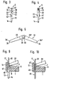
- a base body 1 has an underside 2, an upper side 3 and lateral long sides 4.
- the upper side 3 of the base body 1 is covered between a base plate contact 5 inserted into the base body 1 by a clamping plate contact surface section 6, on the free upper side of which the clamping plate contact surface 7 is formed.
- the clamping plate contact surface 7 is V-shaped from the center of the base body and includes an obtuse angle ⁇ of cica 165 0 .
- the angle ⁇ depending on the purpose of the socket body for a range of 180 0 and 150 ° exert the same 'function according to the invention.
- a spring tongue contact surface 9 which extends relatively steeply downwards to the base top 3, where the base contact 5 has an upper end region 10 from the base body top. 3 protrudes, while a central holding area 11 of the base contact 5 is fixed with a press fit in the base body 1.
- a lower end region 12 of the base contact 5 protrudes vertically downward and merges into a solder connection pin 13 which is square in cross section and has a tip 14 which, for easier insertion of the solder connection pin 13, for example for the bores of PCB holes.
- the longitudinal sides 4 of the base body 1 merge into a base edge 15, which has an inlet bevel 17 on its upper end face 16, which points obliquely downwards from the upper end face 16 towards the center of the base and extends to an inner base edge side surface 18, as shown in particular in FIG 7 shown.
- the inner side edge 18 serves as a support surface 19 for a connecting leg 20 in the IC module 21, which is inserted into the base 1 and by a clamping device 22 according to the form of illustration in FIG. 2 with the back surface 24 of a spring tongue 23 is clamped against the inner side edge 18 of the base edge 15.
- FIG. 1 shows the clamping device 22 composed of a left clamping plate part 25 ′ and a right clamping plate part 25 ′′ in the release position 26 with solid lines and a clamping position 27 with dashed lines, while a locking position 28, which also corresponds to the operating position in FIG. 2 is shown.
- the clamping device 22 has a pivotal connection 29, which "'connects via hinge axis detents 30.
- the two clamp parts 25 and 25' and 25" the two clamp parts 25 a formed in the area of the Gelenkachsen.rasten 30 Schwenkwegbegrenzung 31 which ig according to F in the release position, the 26th, each limited by mutual abutment 1 the pivoting about the release position out.
- the two clamping plate parts 25 'and 25''an upper swivel path limitation 32 is provided, which can limit a swivel path downward beyond the locking position 28, because this enables better work preparation during the manufacture and assembly of the clamping device 22.
- the outer clamping plate edges 34 'and 34'' have a preferably circular arc shape 35 which is at least partially the circular arc contour 37 of the Haltpro correspond to fil elements 36 and rest on a front surface 38 of the spring tongue 23. Projections 39 - as shown in FIG. 6 - are provided between the outer clamping plate edges 34 'and 34 "and extend between the base contacts 5.
- a single base contact 5 is shown in a transverse view, and according to FIG. 4 the same base contact 5 is shown in a longitudinal view, wherein transverse grooves 40 can clearly be seen which cooperate with the connecting legs 20 of the I.C. assembly 21. 4 that anchoring hooks 41 are provided, with which the base contact 5 can additionally be anchored in the base body 1 in its press fit.
- anchoring hooks 41 are provided, with which the base contact 5 can additionally be anchored in the base body 1 in its press fit.
- the base contact 5 merges into the lower end region 12, where a transition shoulder 42 merges into a square cross section.
- the spring tongue 23 extends according to FIG.
- the spring tongue 23 is designed as a holding profile element 36 with the curved contour 37, as is also shown in FIG. 3.
- FIG. 5 again shows the clamping device 22 in the release position 26, how the clamping device 22 is inserted into the base body 1 before assembly and then has the position according to FIG. 1 in solid lines.
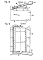
- the base body 1 is shown without base contacts 5 and clamping device 22.
- the raised base edge 15 with the associated run-in slope 17 is shown more clearly.
- the receiving chambers 45 can be seen, in which the base contacts 5 are inserted.
- FIG. 8 shows a top view of the base body 1 according to FIG. 7, in which the receiving chambers 45 and the inlet slope 17 can be seen in a top view. Likewise, the spaces between the individual receiving chambers 45 are shown, into which the clamping plate projections 39 engage and thus prevent the clamping device 22 from slipping in the longitudinal direction of the base.
- FIG. 9 shows another embodiment of a base contact 46, in which the inner side edge 18 is covered by a support contact 47, so that the connecting leg 20 of the IC module 21 is not clamped against the inner side edge 18 but against the support contact 47, which thereby forms the function of the support surface 19. Since the support contact 47 partially fills the contact space 44, the play for the connecting leg 20 of the I.C. assembly 21 when inserting the connecting leg 20 is considerably restricted. The support contact 47 is pulled up to the run-in slope 17, so that the connecting legs 20 get stuck when the I.C. assembly 21 is inserted, thereby reducing the risk of damage.
- FIG. 10 shows a further embodiment for another base contact 48, in which a support contact is also provided and the base contact 48 and the support contact 47 have a tulip-shaped configuration, the tulip base 49 projecting into the base body 1 and thus having a lower overall height for the base body equipped with the IC component is reached.
- the base contact 48 is longitudinally divided, while the base contact 46 according to FIG. 9 has the same embodiment as the base contact 5 and is only supplemented by the support contact 47.
- the support contact 50 is designed as a main contact and the spring tongue 23 has one in the middle holding area 11 to the lower one End area 12 reaching extension.
- the spring tongue 23 is riveted or welded to the solid support contact 50.
- the support contact 50 can also be formed in one piece with the spring tongue 23.
- the clamping plate contact surface 7 is extended somewhat further into the contact surface / m 44 than is the case in the embodiment according to FIG. 1, where the clamping plate contact surface 7 merges into a curve after the outer boundary line 8, as can be clearly seen in FIG. 7.
- FIG. 11 the clamping plate contact surface 7 is extended somewhat further into the contact surface / m 44 than is the case in the embodiment according to FIG. 1, where the clamping plate contact surface 7 merges into a curve after the outer boundary line 8, as can be clearly seen in FIG. 7.
- the spring tongue contact surface 9 therefore extends from the top 3 of the base body 1 to the clamping plate contact surface 7 in a flat course.
- the spring tongue bearing surface 9 forms with the front face 38 of the spring tongue 23 forms an acute angle ⁇ , which is in the order of 0 ° to about 30 and preferably 0 15 0 depending on the position of the clamping device 22nd
- the base edge 15 also has a support contact bearing surface 51, which includes an acute angle ⁇ with a rear side 52 of the support contact 50. The amounts depending on the load of the support contact between> 0 ° and about 30 0, preferably 15 °.
- the contact surface 51 essentially serves to prevent the support contact 50 from being bent beyond the outer longitudinal side 4 of the base body 1 and thus to introduce the risk that an undesired power connection will be established with the corresponding support contact 50 of a neighboring base.
- the support contact 50 has a head region 53 which, like the base edge 15 in accordance with the embodiment of FIG. 1, has an inlet slope 17.
- the run-in slope 17 merges into a nose projection 54 which carries on its front side the supporting surface 19 or a contact zone which can exert a more punctiform load on the connecting leg 20 of an IC module 21.
- the support contact 50 thus takes the main compressive forces on the connecting leg 20 with it a certain range of elasticity, while the spring tongue 23 initially the; Main spring travel forms and then transmits the essential compressive forces of the clamping device 22 from the clamping plate parts 25 through the solid material of the spring tongue 23 from the front surface 38 to the back surface 24 and thus to the connecting leg 20.
- the spring tongue 23 thus has an auxiliary contact and a holding profile function, the main function of course being the introduction of the spring forces for the clamping device.
- the contact space 44 is delimited laterally and downwards by the tulip floor 49 by the back surface 24 of the spring tongue 23 and by the front surface of the support contact 50.
- the base body 1 is formed in one piece, that is to say with the clamping plate contact surface section 6 and the base edge 15 in one piece, then an indentation is formed by the spring tongue contact surface 9 on the one side and the support contact contact surface 51 on the base edge side, in which the spring tongue 23 and the support contact 50 composite socket contact 55 can be used.
- a test base 56 which has a lever device 57.
- a recess 59 is provided in the actuating lever 58, into which an actuating pin 60 protrudes.
- the actuating pin 60 can be the articulated axis catch 30, which either extends directly or protrudes into the recess 59 via a driver 61 and thus enables the clamping device 22 to be pivoted from the release position via the clamping position 27 into the locking position 28 and back via the actuating lever 58.
- FIG. 13 shows a top view of the device according to FIG. 12, which essentially corresponds to the top view of the illustration according to FIG. 6, in which the actuating lugs 62 with associated locking bolts 63 are also provided.
- the locking bolts 63 can be formed on a clamping plate part 25 'in a small projection curvature, so that they can snap into holes 64 of the actuating lugs 62 due to an elastic deformation of the actuating lugs 62 when they are joined together.
- the actuating lugs 62 are formed in the clamping plate part 25 ′′.
- articulated axis pins 30 can then be inserted, which extend into the lever device 57 in their extension, or in another embodiment a pin of the lever device 57 is inserted into the bore 64 of the actuating lug 62.
- plug connectors or bases which are suitable for series production can be created, which can be easily produced from insulating material and which base contacts can be pressed into the contact chambers provided therein. Since the packing density of the semiconductors requires a small size of the base body, they must be arranged in rows from four sides, which is only possible with a base according to the present invention. Since very high demands are made on the electrical and mechanical properties, miniature contacts with pretensioned contact springs must be found in the limited space available.
- the spring contacts can lose their holding force due to secondary natural vibrations, so that the semiconductors can fall out of the base holder or at least contact fluctuations can result.
- This is an intolerable disadvantage, especially in aerospace applications as well as in electroplating and in other important application areas, which is avoided by the present invention.
- the long-term function Soft contact springs for IC components under environmental influences such as heat, cold, aggressive industrial atmosphere, air humidity, etc. are often not guaranteed.
- the underside of the base should be absolutely solder-tight and the soldering pins should be designed so that there is no risk of floating during automatic soldering in the solder bath.
- the simple shape also contributes to the fact that the contact is already securely fulfilled in the upper region of the contact leg and, thanks to the transverse grooves in the contact region of the contact leg, also an absolutely reliable contact even with oxidized connecting plugs guaranteed. Since the contact is continuously formed in one piece, transition losses can be avoided and there is no risk of being stuck through the firm contact with the clamping plates or at the base edge.
Abstract
Der neue Steckverbinder für I.C.-Baueinheiten weist einen isolierenden Sockelkörper auf, in welchem mehrere Sockelkontakte in einer den Anschlußstiften einer I.C.-Baueinheit entsprechenden Anordnung derart vorgesehen sind, daß die Anschlußstifte der I.C.-Baueinheit gleichmäßig in die Sockelkontakte eingesteckt werden können. Damit alle Steckkontakte tatsächlich einen elektrisch zufriedenstellenden Kontakt bilden, wird eine Klemmvorrichtung vorgesehen, mit welcher die Steckkontakte der I.C.-Baueinheit in den Sockelkontakten festgespannt werden. Um einen Steckverbinder auch dann als zufriedenstellend bezeichnen zu können, wenn Erschütterungen auf den Steckverbinder mit der darin eingesetzten I.C.-Baueinheit einwirken, muß sichergestellt sein, daß weder Einzelkontakte noch die gesamte Baueinheit aden Kontaktschluß mit den Sockelkontakten verlieren. Es wird daher die Klemmvorrichtung, die aus zwei im wesentlichen giebelförmig ausgebildeten Klemmplatten besteht, so zwischen den beiden Reihen der Sockelkontakte angeordnet, daß die Klemmplatten neben einer Lösestellung eine über die Arretierstellung hinaus überführbare Ruhestellung aufweisen, in welcher die Klemmplattenteile aufeinander zu nach unten in Richtung auf die Oberseite des Sockelkörpers geneigt sind, wobei die als massive Federzungen ausgebildeten Federelemente der Sockelkontakte mit einer an dem äußeren Klemmplattenrand anliegenden Vorderfläche gegen die Steckkontakte der I.C.-Baueinheiten in einem ausreichend starken Maß drücken, so daß auch bei Erschütterungen ein Lösen der Steckverbindung nicht möglich ist, da sonst die Klemmplatten über eine zunächst größere Kraft erfordernde Arretierstellung hinaus in die Lösestellung überführt werden müßten.The new connector for I.C. units has an insulating base body, in which a plurality of base contacts are provided in an arrangement corresponding to the pins of an I.C. unit such that the pins of the I.C. unit can be inserted evenly into the base contacts. So that all plug contacts actually form an electrically satisfactory contact, a clamping device is provided with which the plug contacts of the I.C. assembly are clamped in the base contacts. In order to be able to describe a connector as satisfactory even if vibrations act on the connector with the I.C. assembly inserted therein, it must be ensured that neither individual contacts nor the entire assembly lose contact with the base contacts. It is therefore the clamping device, which consists of two substantially gable-shaped clamping plates, so arranged between the two rows of base contacts that the clamping plates have a release position and a rest position beyond the locking position, in which the clamping plate parts towards each other downwards in the direction are inclined on the upper side of the base body, the spring elements of the base contacts, which are designed as solid spring tongues, with a front surface lying against the outer edge of the clamping plate pressing against the plug contacts of the IC components to a sufficiently strong degree so that the connector cannot be released even when shaken is, otherwise the clamping plates would have to be transferred into the release position beyond a locking position that initially requires greater force.
Description
Die Erfindung betrifft einen Steckverbinder für I.C.-Baueinheiten gemäß dem Oberbegriff des Anspruchs l.The invention relates to a connector for I.C. units according to the preamble of claim l.
Ein derartiger Steckverbinder ist beispielsweise aus der US-PS 4 266 840 bekannt. Der darin beschriebene Steckverbinder weist zwei Klemmplattenteile auf, welche über eine oberhalb den Klemmplattenteilen angeordnete und gesonderte Scharnierverbindung diese schwenkbeweglich verbindet, so daß beim Einsetzen einer I.C.-Baueinheit in den Sockelkörper, die Unterseite der I.C.-Baueinheit auf die Schwenkverbindung drückt. Dabei werden mit zunehmender Einsetztiefe der I.C.-Baueinheit die Klemmplatten gegen die Sockelkontaktfedern gedrückt, welche ihrerseits die Anschlußbeine der I.C.-Baueinheit zunehmend fester gegen die von Randbereichen des Sockelkörpers gebildeten Stützflächen andrücken. Dies bedeutet, daß die I.C.-Baueinheit bereits während des Einsetzens in den Sockel zunehmend festgelegt wird und damit die Gefahr besteht, daß erstens die I.C.-Baueinheit nicht die vorgesehene Endposition erreicht und zweitens durch den zunehmenden Einsetzdruck die Anschlußbeine verbogen werden können, so daß Ungenauigkeiten bei einem gleichmäßigen Anpreßdruck der Sockelkontakte an die mehrfachen Anschlußbeine zu Störungen der elektrischen Funktion führen können. Ähnliche Probleme treten bei der in der US-PS 4 189 199 beschriebenen Sockelvorrichtung auf, bei welcher die I.C.-Baueinheit auf Plattenelemente und über diese betätigte Federkontakte während des Einsetzvorgangs drückt. Weitere Sockelhalter, bei welchen die Federkraft bereits während des Einsetzens der I.C.-Baueinheit in den Sockel durch den Einsetzvorgang wirksam wird, sind in der US-PS 3 883 207 und 3 750 085 mit den sich daraus ergebenden Nachteilen beschrieben. Wenn jedoch das Hauptanwendungsgebiet der Sockelkörper bei beispielsweise auf Leiterplatten angeordneten elektrischen Schaltungen angestrebt wird, bei welchen eine dauerhafte und zuverlässige Funktion der I.C.-Baueinheit erforderlich ist, dann ist von besonderer Bedeutung, daß erstens die I.C.-Baueinheit die gewünschte Position eindeutig erreicht und zum anderen möglichst jegliche Kontaktverbiegungen bei den Kontaktbeinen der I.C.-Baueinheit vermieden werden. Hierzu sind die soeben beschriebenen Sockelanordnungen wenig geeignet. Daher wurden Sockelanordnungen entwickelt, bei welchen die I.C.-Baueinheit erst in den Sockel eingesetzt und anschließend die Sockelbeine festgeklemmt werden. Solche Anordnungen sind beispielsweise in den US-PS 3 997 227 oder 4 054 347 oder 4 266 839 beschrieben, wodurch mittig angeordnete Stangen eine Druckkraft bzw. Zugkraft oder_Drehschubkraft auf die Federkontakte ausgeübt wird. Da solche Anordnungen sehr aufwendig sind und bei der Preisrelation zu den I.C.-Baueinheiten wirtschaftlich nicht vernünftig herstellbar sind, konnten sich diese Anordnungen für die vorgesehenen Einsatzgebiete nicht durchsetzen.Such a connector is known for example from US Pat. No. 4,266,840. The connector described therein has two clamping plate parts which pivotally connect them via a separate hinge connection arranged above the clamping plate parts, so that when an IC module is inserted into the base body, the underside of the IC module presses on the swivel connection. As the depth of insertion of the IC module increases, the clamping plates are pressed against the base contact springs, which in turn press the connecting legs of the IC module increasingly firmly against the support surfaces formed by edge regions of the base body. This means that the IC module is already increasingly fixed during insertion into the socket and there is therefore a risk that firstly the IC module will not reach the intended end position and secondly by the increasing insertion pressure, the connecting legs can be bent, so that inaccuracies in a uniform contact pressure of the base contacts on the multiple connecting legs can lead to malfunctions in the electrical function. Similar problems occur with the socket device described in US Pat. No. 4,189,199, in which the IC assembly presses on plate elements and spring contacts actuated via them during the insertion process. Further socket holders, in which the spring force is already effective during the insertion of the IC assembly into the socket through the insertion process, are described in US Pat. Nos. 3,883,207 and 3,750,085 with the resulting disadvantages. However, if the main area of application of the socket body is aimed at, for example, electrical circuits arranged on printed circuit boards, in which a permanent and reliable function of the IC assembly is required, then it is of particular importance that firstly the IC assembly uniquely reaches the desired position and second Avoid any contact bends in the contact legs of the IC assembly. The base arrangements just described are not very suitable for this. Therefore, socket arrangements have been developed in which the IC assembly is first inserted into the socket and then the socket legs are clamped in place. Such arrangements are described, for example, in US Pat. No. 3,997,227 or 4,054,347 or 4,266,839, as a result of which centrally arranged rods are exerted on the spring contacts by a compressive force or tensile force or rotational thrust force. Since such arrangements are very complex and cannot be produced economically with regard to the price relation to the IC components, these arrangements could not prevail for the intended fields of application.
Es wurde daher eine einfachere Lösung mit Kunststoffklappteilen vorgeschlagen, wie sie in der US-PS 4 193 656 beschrieben ist. Bei dieser Lösung dient die Klappvorrichtung aufgrund der gewählten Materialwahl gleichzeitig als Federelement, das auf die Anschlußbeine die gewünschte Federkraft aufbringen soll. Abgesehen von der Tatsache, daß diese Sockelkonstruktion den Nachteil hat, daß ebenfalls die Federkraft des Kunststoffbetätigungsteils bereits während des Einsetzens der I.C.-Baueinheit in den Sockel aufgebracht wird, besteht ein weiterer Nachteil darin, daß ein solch elastisches Kunststoffmaterial keine gleichmäßige Andruckkraft auf alle Anschlußkontakte gleichzeitig ausüben kann.A simpler solution with plastic folding parts has therefore been proposed, as described in US Pat. No. 4,193,656. In this solution, the folding device also serves as a due to the choice of material Spring element that is to apply the desired spring force to the connecting legs. In addition to the fact that this base construction has the disadvantage that the spring force of the plastic actuating part is already applied to the base during the insertion of the IC module, there is a further disadvantage that such an elastic plastic material does not have a uniform pressure force on all connection contacts at the same time can exercise.
Eine andere Sockelausführung mit einem Klappmechanismus, der erst bei eingesetzter I.C.-Baueinheit betätigt wird, ist in der US-PS 3 820 054 beschrieben. Obwohl die darin beschriebene Lösung zunächst einfach erscheint, hat diese Sockelkonstruktion den Nachteil, daß sie nur als Einzelsockel mit großem Abstand zu anderen Sockeln angeordnet werden kann, weil die Seitenflächen des Sockels für die Betätigung der Klemmvorrichtung Abstand zueinander haben müssen.Another base design with a folding mechanism, which is only activated when the I.C. unit is inserted, is described in US Pat. No. 3,820,054. Although the solution described therein initially appears simple, this base construction has the disadvantage that it can only be arranged as a single base with a large distance from other bases, because the side surfaces of the base must be spaced from one another for the actuation of the clamping device.
Der Nachteil, nicht einen Sockel an einen anderen sowohl in Längsrichtung als auch in Querrichtung so ansetzen zu können, was bei gedruckten Schaltungen zunächst von Bedeutung ist, ob diese direkt mit I.C.-Baueinheiten oder mit dazwischengefügten Sockeln bestückt werden, haftet auch der Sockelanordnung gemäß der US-PS 4 266 840 an. Denn auch bei dieser Sockelanordnung ist dierdurch die Konstruktion der Federkontakte bedingte Bauform,eine Identität zwischen Kontaktbeinen der I.C.-Baueinheit und Lötanschlußstiften des Sockels verschieden, so daß eine weitere platzsparende Konstruktion der Sockelseitenwände unberücksichtigt bleiben kann. Darüber hinaus hat die Sockelkonstruktion gemäß der US-PS 4 266 840 den Nachteil, daß eine gesonderte Sicherung über Sperrklinken vorgesehen werden muß, welche verhindert, daß bei Erschütterungen des Sockels sich die Klemmplatten entsprechend der auf sie wirkenden Federkräfte aus dem labilen Haltenzustand in den stabileren Lösezustand aufschwenken und damit die I.C.-Baueinheit in ihrem Kontakt zu den Sockelkontakten freigeben würden. Eine solche Klinkensicherung ist jedoch ein weiterer Nachteil, den eine einfache und preiswerte Sockelkonstruktion verbietet.The disadvantage of not being able to attach one socket to another in both the longitudinal and transverse directions, which is important in the case of printed circuits, whether these are fitted directly with IC modules or with sockets inserted in between, is also liable for the socket arrangement according to the U.S. Patent 4,266,840. Even in this arrangement, the base r caused by the construction of the spring contacts design, an identity between the contact legs of the IC package and Lötanschlußstiften of the base is different, so that a further space-saving design of the base side walls may be disregarded. In addition, the base construction according to US Pat. No. 4,266,840 has the disadvantage that a separate securing device has to be provided via pawls, which prevents the clamping plates from shaking the base according to the spring forces acting on them from the unstable holding state to the more stable one Swing open the release state and thus the IC assembly in would release their contact to the socket contacts. However, such latch locking is a further disadvantage that a simple and inexpensive base construction prohibits.
Es ist daher Aufgabe der Erfindung, einen Steckverbinder für I.C.-Baueinheiten gemäß dem Oberbegriff des Anspruchs 1 derart zu schaffen, daß der Steckverbinder in seinen Außenabmessungen und seiner Sockelkontaktanordnung bei nahezu allen Schaltungen die für die unmittelbare Bestük-' kung mit I.C.-Baueinheiten vorgesehen sind, auch bei enger Gruppenanordnung einsetzbar ist und daß dieser Steckverbinder ein Festklemmen der I.C.-Baueinheit nach dessen Einsetzen in die Sockelkontakte einfach ermöglicht, ohne daß dabei auf eine besonders einfache und preiswerte Konstruktion verzichtet werden muß.It is therefore an object of the invention to provide a connector for IC modules according to the preamble of
Diese Aufgabe wird durch die kennzeichnenden Merkmale des Anspruchs 1 gelöst. Vorteilhafte Weiterbildungen ergeben sich aus den Unteransprüchen.This object is achieved by the characterizing features of
Ein besonderer Vorteil der Erfindung ist darin zu sehen, daß der neue Steckverbinder auch für die nachträgliche Bestückung von bereits bestehenden gedruckten Schaltungen verwendet werden kann, weil beim Auslöten einer beschädigten I.C.-Baueinheit an deren Stelle der neue Steckverbinder eingelötet werden kann und damit werden die übrigen Elemente der gedruckten Schaltung nicht durch wiederholte Lötvorgänge gefährdet. Ein weiterer Austausch der einzelnen I.C.-Baueinheiten ist nämlich dann durch einfaches Öffnen und Schließen der Sockelkontakte möglich. Dies setzt jedoch voraus, daß die Abmessungen des neuen Steckverbinders im wesentlichen denen der I.C.-Baueinheit selbst entsprechen und darüber hinaus die Sockelkontakte Lötanschlußstifte oder Wrapanschlüsse aufweisen, welche in ihrer Anordnung der Anordnung der Anschlußbeine einer I.C.-Baueinheit entsprechen. So wird beispielsweise besonders vorteilhaft der Lötanschlußstift des neuen Steckverbinders mit quadratischem Querschnitt gewählt, weil dadurch ein "Aufschwimmen" des Sockels beim automatischen Löten in einem Lötbad nicht stattfinden kann, denn das flüssige Lot findet zwischen den Seitenwänden des im Querschnitt quadratischen Lötanschlußstiftes und dem Rundloch in der Leiterplatte genügend Platz, um durchzutreten und damit ein Aufschwimmen zu verhindern.A particular advantage of the invention can be seen in the fact that the new connector can also be used for the subsequent assembly of already existing printed circuits, because when a damaged IC component is unsoldered, the new connector can be soldered in its place and the others become Printed circuit elements not at risk from repeated soldering. A further exchange of the individual IC components is then possible simply by opening and closing the socket contacts. However, this presupposes that the dimensions of the new connector essentially correspond to those of the IC module itself and, moreover, the base contacts have solder pins or wrap connections which correspond in their arrangement to the arrangement of the connection legs of an IC module. For example, the solder pin of the new plug is particularly advantageous connector with a square cross-section selected, because this means that the base cannot "float" during automatic soldering in a solder bath, because the liquid solder finds enough space between the side walls of the square cross-sectional soldering pin and the round hole in the circuit board to penetrate and thus to prevent floating.
Ein weiterer wesentlicher Vorteil der Erfindung ist darin zu sehen, daß der neue Steckverbinder auch bei Erschütterungen die I.C.-Baueinheit sicher festhalten kann, da die Klemmplatten in der Arretierungsstellung eine stabile Lage haben, und bei Erschütterungen erst in die noch stärker federbelastete Spannstellung überführt werden müßten, daß sie aus der labilen Spannstellung in eine wieder stabile Lösestellung gelangen können. Durch die Schaffung einer über die Spannstellung hinausgehenden Arretierungsstellung wird somit eine besonders einfache und doch äußerst wirksame Sicherung der eingesetzten I.C.-Baueinheiten erreicht.Another significant advantage of the invention is that the new connector can hold the IC module securely even when shaken, since the clamping plates have a stable position in the locking position, and should only be transferred to the even more spring-loaded clamping position when shaken that they can move from the unstable clamping position to a stable release position again. By creating a locking position that goes beyond the clamping position, a particularly simple yet extremely effective securing of the I.C. units used is achieved.
Damit die Konstruktion des neuen Steckverbinders auch bei Lösestellung einfach bleibt, ist einerseits vorgesehen, daß die Scharnierverbindung zwischen den Klemmplattenteilen eine Schwenkwinkelbegrenzung aufweist, so daß die auch in Lösestellung auf die äußeren Klemmplattenränder wirkenden Federkräfte die Klemmplattenvorrichtung in eingespannter Anordnung in der Sockelvorrichtung festhalten. Dies bedeutet, daß bei dem neuen Steckverbinder die äußeren Klemmplattenränder unmittelbar von den Federkontakten und durch gesondert auszubildenden Halteprofilelemente gehalten werden, was sowohl konstruktiv als auch kostenmäßig aufwendig wäre. Vorteilhafterweise werden die Halteprofile und die Form der äußeren Klemmplattenränder bogensegmentförmig oder sogar kreisbogensegmentförmig ausgebildet, so daß die Klemmplattenränder als Lager und die Federelemente als Lagerschalen dienen können. In diesem Lager vorgesehene Querrillen erhöhen bei der durch das Lager einerseits erzielbaren präzisen Führung andererseits die Reibkräfte, so daß ein gezieltes Überführen von der Lösestellung über die Spannstellung in die Arretierstellung und zurück möglich ist. Für diesen Zweck wird vorteilhafterweise an wenigstens einer Stirnseite der Klemmplattenteile ein Betätigungszapfen ausgebildet, welcher auch beidseitig angeordnet sein kann. Hierzu eignet sich besonders vorteilhaft die gewählte Konstruktion der an die Klemmplatten angeformten Scharnierteile und/oder der Scharnierstift der Schwenkverbindung.So that the construction of the new connector remains simple even in the release position, it is provided on the one hand that the hinge connection between the clamping plate parts has a swivel angle limitation, so that the spring forces acting in the released position on the outer clamping plate edges hold the clamping plate device in a clamped arrangement in the base device. This means that in the new connector, the outer edges of the clamping plate are held directly by the spring contacts and by separately designed retaining profile elements, which would be both constructive and costly. Advantageously, the holding profiles and the shape of the outer clamping plate edges are formed in the shape of an arc segment or even in the form of a circular segment, so that the clamping plate edges can serve as bearings and the spring elements can serve as bearing shells. In this camp provided transverse grooves on the one hand through the camp he Targetable precise guidance on the other hand, the frictional forces, so that a targeted transfer from the release position to the clamping position in the locking position and back is possible. For this purpose, an actuating pin, which can also be arranged on both sides, is advantageously formed on at least one end face of the clamping plate parts. For this purpose, the selected construction of the hinge parts formed on the clamping plates and / or the hinge pin of the swivel connection is particularly advantageous.
Da die Arretierstellung nur durch einen Anschlagpunkt für die Klemmplattenvorrichtung an der Oberseite des Sockelkörpers ausgebildet sein muß, würde grundsätzlich das Vorsehen eines entsprechenden Anschlags an der Oberseite des Sockelkörpers für diesen Zweck ausreichen. Es ist jedoch besonders vorteilhaft, die Oberfläche des Sockelkörpers V-förmig mit einem dazwischen befindlichen großen Winkel auszubilden, weil damit bei Erschütterungen nicht Punktbelastungen auf die Klemmplattenvorrichtung übertragen werden, sondern weil dadurch Klemmplattenanlageflächenerreicht werden können, welche die nachteiligen Punktbelastungen ausschließen und damit zu einer weiteren Sicherung der Klemmplattenteile in der Arretierstellung beitragen. Die Ausbildung dieser Klemmplattenanlageflächen kann bereits bei der Herstellung des Klemmplattenkörpers im Druck- oder Spritzverfahren ohne wesentliche zusätzliche Werkzeugkosten berücksichtigt werden.Since the locking position only has to be formed by a stop point for the clamping plate device on the top of the base body, the provision of a corresponding stop on the top of the base body would in principle be sufficient for this purpose. However, it is particularly advantageous to form the surface of the base body in a V-shape with a large angle located therebetween, because it does not transmit point loads to the clamping plate device in the event of vibrations, but because clamping plate contact surfaces can thereby be reached which exclude the disadvantageous point loads and thus to a further point Help secure the clamping plate parts in the locking position. The formation of these clamping plate contact surfaces can already be taken into account during the production of the clamping plate body in the printing or spraying process without significant additional tool costs.
Ebenso einfach und damit vorteilhaft ist die Ausbildung der Sockelkontakte,die weitgehend oder ganz einstückig ausgebildet in den Sockelkörper eingepreßt werden können. Da die oberen Endbereiche der Sockelkontakte als Federzungen ausgebildet sind, liefern sie den gewünschten Federdruck auf die äußeren Klemmplattenränder. Um die Federzungen mit den Sockelkontakten unter eine entsprechende Vorspannung in den Sockelkörper einsetzen zu können, ist besonders vorteilhaft, wenn eine Federzungenanlagefläche an der Oberseite des Sockelkörpers ausgebildet ist, die sich in Form einer Kerbe in den Sockelkörper hinein erstrecken kann. Hierzu genügt, wenn die Federzunge mit der Federzungenanlagefläche einen kleinen Winkel einschließt, der im wesentlichen den Federweg bestimmt.Equally simple and therefore advantageous is the design of the base contacts, which can be pressed into the base body largely or in one piece. Since the upper end areas of the base contacts are designed as spring tongues, they deliver the desired spring pressure on the outer clamping plate edges. In order to be able to insert the spring tongues with the base contacts under a corresponding pretension in the base body, it is particularly advantageous if a spring tongue contact surface is formed on the top of the base body, which can extend into the base body in the form of a notch. It is sufficient if the spring tongue with the tongue-F Eder bearing surface a small angle, which determines the amount of travel substantially.
Bei einer einfacheren Ausführungsform des neuen Steckverbinders werden die Kontaktbeine der I.C.-Baueinheit von der Federzunge gegen eine Stützfläche gepreßt, welche von einem hochgezogenen Rand des Sockelkörpers gebildet wird. Dieser hochgezogene Rand kann vorteilhafterweise eine Einlaufschräge aufweisen, die das Einsetzen der I.C.-Baueinheit in den Sockel erleichtert.In a simpler embodiment of the new connector, the contact legs of the I.C. assembly are pressed by the spring tongue against a support surface, which is formed by a raised edge of the base body. This raised edge can advantageously have a run-in slope that facilitates the insertion of the I.C. assembly into the base.
Bei einer anderen Ausführungsform des neuen Steckverbinders wird die Stützfläche von einem Stützkontakt gebildet, der am oberen Endbereich des Sockelkontakts mit diesem ausgebildet ist, so daß der obere Endbereich des Sockelkontakts einerseits aus der Federzunge und andererseits aus dem Stützkontakt besteht. So kann beispielsweise eine tulpenähnliche Lösung für den oberen Endbereich des Sockelkontakts gewählt werden, bei welchem durch zwei entsprechende Einschnitte ein Teil des Sockelkontakts als Federzunge ausgebildet wird. Wenn besonders hohe Festhaltekräfte angestrebt werden, dann wird der Stützkontakt weitgehend massiv mit dem Sockelkontakt ausgebildet und eine separate Federzunge mit dem Sockelkontakt verbunden, so daß sich die Federzunge vom unteren Endbereich durch den mittleren Haltebereich in den oberen Endbereich des Sockelkontakts erstreckt. Bei einer solchen Ausführungsform kann dann vorteilhafterweise der Stützkontakt einen Kopfabschnitt aufweisen, der dem Stützkontakt im oberen Bereich eine weitere Festigkeit verleiht und der eine nasenförmige Kontaktfläche aufweist, wodurch eine stärker punktförmige und weniger flächenförmige Belastung auftritt, was zu einem intensiveren Kontakt zwischen Kontaktbein der I.C.-Baueinheit und dem Sockelkontakt führt. Durch den Stützkontakt wird neben den Elastizitätsmodulen in der Klemmplatte und im wesentlichen in der Federzunge ein weiteres Elastizitätsmoment erreicht. Dies ist besonders deshalb wichtig, weil aufgrund der geringen Konstruktionsabmessungen möglichst alle Teile des neuen Steckverbinders funktionell ausgenützt werden müssen.In another embodiment of the new connector, the support surface is formed by a support contact which is formed at the upper end region of the base contact with the latter, so that the upper end region of the base contact consists on the one hand of the spring tongue and on the other hand of the support contact. For example, a tulip-like solution can be selected for the upper end region of the base contact, in which part of the base contact is formed as a spring tongue by means of two corresponding incisions. If particularly high retention forces are desired, then the support contact is largely solid with the base contact and a separate spring tongue is connected to the base contact, so that the spring tongue extends from the lower end region through the middle holding region into the upper end region of the base contact. In such an embodiment, the support contact can then advantageously have a head section which gives the support contact a further strength in the upper region and which has a nose-shaped contact surface, as a result of which a more punctiform and less flat load occurs, which leads to more intensive contact between the contact leg of the IC Unit and the base contact leads. The support contact is in addition to the elasticity modules in the clamping plate and essentially Lichen achieved another elastic moment in the spring tongue. This is particularly important because, due to the small construction dimensions, all parts of the new connector have to be used functionally.
Hierzu ist ein weiterer Vorteil, wenn der Stützkontakt in einem geringen Abstand auf eine Stützkontaktanlagefläche trifft, die im Sockelkörperrand ausgebildet sein kann und damit einerseits ein Überdehnen der Stützkontakte beim Einsetzen von I.C.-Baueinheiten oder beim sonstigen Hantieren an den Kontakten verhindert und andererseits die Gefahr einer Kontaktberührung mit einem Nachbarkontakt des benachbarten Sockels verhindert.This is a further advantage if the support contact meets a support contact contact surface at a short distance, which can be formed in the edge of the base body and thus on the one hand prevents the support contacts from being overstretched when inserting IC modules or when fiddling with the contacts, and on the other hand the risk of Prevents contact with a neighboring contact of the neighboring base.
Natürlich kann der neue Steckverbinder auch mit Prüfsockelhalterungen zu einem ausgesprochenen Prüfsockel-Steckverbinder ausgebildet werden, indem der neue Steckverbinder lediglich mit Betätigungszapfen versehen wird, welche vorteilhaft die Scharnierzapfen sind, die in eine entsprechende Hebelvorrichtung eines Prüfsockels hineinreichen. Dadurch wird auch für den Bereich der Prüfsockel eine vielseitige Anwendbarkeit des neuen Steckverbinders erreicht, was ein weiterer Vorteil für eine einheitliche Konstruktion des Steckverbinders ist. Weitere Vorteile und Einzelheiten der Erfindung ergeben sich aus der nachfolgenden Beschreibung anhand der beigefügten Zeichnung.Of course, the new connector can also be configured with test socket brackets to form a pronounced test socket connector, in that the new connector is only provided with actuating pins, which are advantageously the hinge pins that extend into a corresponding lever device of a test socket. This means that the new connector can also be used for the test socket area, which is a further advantage for a uniform connector design. Further advantages and details of the invention will become apparent from the following description with reference to the accompanying drawings.
Darin zeigt:
- Fig. 1 einen Schnitt quer zur Längsrichtung des Steckverbinders, bei welchem die Klemmplattenteile einmal in Lösestellung und gestrichelt in Spannstellung dargestellt sind;
- Fig. 2 eine ähnliche Darstellung wie in Fig. l, wobei jedoch die Klemmplattenteile in Arretierstellung gezeigt sind und wobei die I.C.-Baueinheit im ganzen dargestellt ist;
- Fig. 3 die Queransicht einer ersten Ausführungsform des Sockelkontakts,der bei einer Ausführungsform gemäß Fig. 1 und 2 verwendet wird;
- Fig. 4 die Längsansicht des Sockelkontakts gemäß Fig. 3;
- Fig. 5 eine Queransicht der Klemmplattenvorrichtung;
- Fig. 6 eine Draufsicht auf die Klemmplattenvorrichtung gemäß Fig. 1 und 2 und 5;
- Fig. 7 einen Schnitt durch einen Sockelkörper, in welchen noch keine Sockelkontakte eingesetzt sind;
- Fig. 8 eine Draufsicht auf den Sockelkörper gemäß Fig. 7;
- Fig. 9 einen Schnitt durch eine andere Ausführungsform eines Sockelkontakts,bei welchem die Stützfläche mit dem Sockelkontakt ausgebildet ist;
- Fig. 10 eine weitere Ausführungsform des Sockelkontakts ähnlich gemäß Fig. 9, welcher tulpenförmig ausgebildet ist;
- Fig. 11 eine weitere Ausführung eines Sockelkontakts mit einem besonderen Stützkontakt und daran ausgepaßten Sockelkörper;
- Fig. 12 eine Seitenansicht einer Hebelvorrichtung eines Prüfsockels; und
- Fig. 13 eine Draufsicht auf die Hebelvorrichtung gemäß Fig. 12.
- Figure 1 shows a section transverse to the longitudinal direction of the connector, in which the clamping plate parts are shown once in the release position and dashed lines in the clamping position.
- Fig. 2 is a similar representation as in Fig. 1, but with the clamping plate parts are shown in the locking position and wherein the IC assembly in whole is shown;
- 3 shows the transverse view of a first embodiment of the base contact, which is used in an embodiment according to FIGS. 1 and 2;
- FIG. 4 shows the longitudinal view of the base contact according to FIG. 3;
- 5 is a transverse view of the clamping plate device;
- 6 shows a plan view of the clamping plate device according to FIGS. 1 and 2 and 5;
- 7 shows a section through a base body in which no base contacts have yet been inserted;
- 8 shows a plan view of the base body according to FIG. 7;
- F ig. 9 shows a section through another embodiment of a base contact, in which the support surface is formed with the base contact;
- F ig. 10 shows a further embodiment of the base contact similar to FIG. 9, which is tulip-shaped;
- 11 shows a further embodiment of a base contact with a special support contact and base body fitted thereon;
- 12 shows a side view of a lever device of a test base; and
- 13 is a plan view of the lever device according to FIG. 12.
Gemäß Fig. 1 weist ein Sockelkörper 1 eine Unterseite 2, eine Oberseite 3 und seitliche Längsseiten 4 auf. Die Oberseite 3 des Sockelkörpers 1 wird zwischen in den Sockelkörper 1 eingesetzte Sockelkontakte 5 von einem Klemmplattenanlageflächenabschnitt 6 überdeckt, an dessen freier Oberseite die Klemmplattenanlagefläche 7 ausgebildet ist. Die Klemmplattenanlagefläche 7 ist V-förmig von der Sockelkörpermitte aus ausgebildet und schließt einen stumpfen Winkel α von cica 165 0 ein. Natürlich kann der Winkel α je nach Einsatzzweck des Sockelkörpers für einen Bereich von 180 0 und 150° dieselbe erfindungsgemäße'Funktion ausüben. An den äußeren Grenzlinien 8 der Klemmplattenablagefläche 7 geht diese in eine Federzungenanlagefläche 9 über, welche sich relativ steil nach unten zur Sockeloberseite 3 erstreckt, wo der Sockelkontakt 5 mit einem oberen Endbereich 10 aus der Sockelkörperoberseite. 3 herausragt, während ein mittlerer Haltebereich 11 des Sockelkontakts 5 mit einem Preßsitz in dem Sockelkörper 1 befestigt ist. Von der Unterseite 2 des Sockelkörpers 1 steht ein unterer Endbereich 12 des Sockelkontakts 5 senkrecht nach unten ab und geht in einen Lötanschlußstift 13 über, welcher im Querschnitt vierkantförmig ausgebildet ist und eine Spitze 14 aufweist, die zur leichteren Einführung des Lötanschlußstiftes 13 beispielsweise für die Bohrungen von Leiterplattenlöchern dient.1, a
Die Längsseiten 4 des Sockelkörpers 1 gehen in einen Sockelrand 15 über, der an seiner oberen Stirnsteite 16 eine Einlaufschräge 17 aufweist, die von der oberen Stirnseite 16 schräg nach unten zur Sockelmitte hin zeigt und bis zu einer inneren Sockelrandseitenfläche 18 reicht, wie insbesondere in Fig. 7 dargestellt.The longitudinal sides 4 of the
An dieser Stelle sei darauf hingewiesen, daß einander entsprechende Teile in allen Figuren mit gleichen Bezugszeichen versehen sind, so daß eine gesonderte Beschreibung hierfür entfallen kann.At this point, it should be pointed out that corresponding parts are provided with the same reference numerals in all figures, so that a separate description for this can be omitted.
Der innere Seitenrand 18 dient bei dieser Ausführungsform als Stützfläche 19 für ein Anschlußbein 20 bei der I.C.-Baueinheit 21, das in den Sockel 1 eingesteckt ist und von einer Klemmvorrichtung 22 gemäß der Darstellungsform von Fig. 2 mit der Rücen- Fläche 24 einer Federzunge 23 gegen den inneren Seitenrand 18 des Sockelrandes 15 festgeklemmt wird.In this embodiment, the
Dabei ist in Fig. 1 die aus einem linken Klemmplattenteil 25' und einem rechten Klemmplattenteil 25" zusammengesetzte Klemmvorrichtung 22 in Lösestellung 26 mit ausgezogenen Linien und eine Spannstellung 27 mit gestrichelten Linien dargestellt, während eine Arretierstellung 28, die auch der Betriebstellung entspricht in Fig. 2 dargestellt ist.1 shows the
Die Klemmvorrichtung 22 weist eine Schwenkverbindung 29 auf, welche die beiden Klemmplattenteile 25' und 25" mittels Gelenkachsenrasten 30 verbindet. In der Darstellung gemäß Fig. 2 weisen die beiden Klemmplattenteile 25' und 25" eine im Bereich des Gelenkachsen.rasten 30 ausgebildete Schwenkwegbegrenzung 31 auf, welche bei der Lösestellung 26 gemäß Fig., 1 durch gegenseitigen Anschlag aneinander den Schwenkweg über die Lösestellung hinaus begrenzt. Ebenso ist an der Oberseite der beiden Klemmplattenteile 25' und 25'' eine obere Schwenkwegbegrenzung 32 vorgesehen, die einen Schwenkweg nach unten über die Arretierstellung 28 hinaus begrenzen kann, weil dadurch bei der Herstellung und Montage der Klemmvorrichtung 22 eine bessere Arbeitsvorbereitung möglich ist. Von der Funktion der Klemmvorrichtung 22 selbst ist es bei der gezeigten Ausfürhungsform nicht notwendig, eine obere Schwenkwegbegrenzung 32 vorzusehen, da die Unterseite 33' bzw. 33" der Klemmplattenteile 25' bzw. 25'' ohnehin in Arretierstellung 28 an der Klemmplattenanlagefläche 7 anliegt und damit den Schwenkweg begrenzt.The clamping
Die äußeren Klemmplattenränder 34' bzw. 34'' weisen eine vorzugsweise kreisbogenförmige Bogenkontur 35 auf, welche zumindest teilweise der Kreisbogenkontur 37 der Halteprofilelemente 36 entsprechen und an einer Vorderfläche 38 der Federzunge 23 anliegen. Zwischen den äußeren Klemmplattenrändern 34' und 34" sind Vorsprünge 39 - wie in Fig. 6 dargestellt - vorgesehen, welche sich zwischen die Sockelkontakte 5 erstrecken.The outer clamping plate edges 34 'and 34''have a preferably
Gemäß Fig. 3 ist ein einzelner Sockelkontakt 5 in Queransicht dargestellt, und gemäß Fig. 4 ist derselbe Sockelkontakt 5 in Längsansicht dargestellt, wobei deutlich Querrillen 40 zu erkennen sind, welche in Reibwirkung mit den Anschlußbeinen 20 der I.C.-Baueinheit 21 zusammenwirken. Außerdem ist bei'der Darstellung gemäß Fig. 4 zu erkennen, daß Verankerungshaken 41 vorgesehen sind, mit welchen der Sockelkontakt 5 in seinem Preßsitz zusätzlich im Sockelkörper 1 verankert werden kann. In der Höhe etwa des Verankerungshakens 41 geht der Sockelkontakt 5 in den unteren Endbereich 12 über, wo ein Übergangsabsatz 42 in einen Vierkantquerschnitt übergeht. An der oberen Grenze des mittleren Haltebereiches 11, an der die Federzunge 23 gemäß Fig. 3 bis zu einem Federzungenende 43 reicht, ist ein Kontaktraum 44 vorgesehen, der gleichzeitig den Abstand zwischen der Stützfläche 19 und der Rückenfläche 24 der Federzunge 23 begrenzt. Die Federzunge 23 ist bei der erfindungsgemäßen Ausführungsform als Halteprofilelement 36 mit der Bogenkontur 37 ausgebildet, wie ebenfalls in Fig. 3 dargestellt.According to FIG. 3, a
In Fig. 5 ist nochmals die Klemmvorrichtung 22 in der Lösestellung 26 dargestellt, wie die Klemmvorrichtung 22 vor der Montage in den Sockelkörper 1 eingesetzt wird und dann die Position gemäß Fig. 1 in ausgezogenen Linien aufweist.5 again shows the
Gemäß Fig. 7 ist der Sockelkörper 1 ohne Sockelkontakte 5 und Klemmvorrichtung 22 dargestellt. Dabei wird der hochgezogene Sockelrand 15 mit der zugehörigen Einlaufschräge 17 deutlicher dargestellt. Zudem sind die Aufnahmekammern 45 zu erkennen, in welche die Sockelkontakte 5 eingesetzt werden.7, the
Gemäß Fig. 8 ist eine Draufsicht auf den Sockelkörper 1 gemäß Fig. 7 dargestellt, bei dem die Aufnahmekammern 45 und die Einlaufschräge 17 in Draufsicht zu erkennen sind. Ebenso sind die Zwischenräume zwischen den einzelnen Aufnahmekammern 45 dargestellt, in welche die Klemmplattenvorsprünge 39 eingreifen und damit ein Verrutschen der Klemmvorrichtung 22 in Sockellängsrichtung verhindern.8 shows a top view of the
Gemäß Fig. 9 ist eine andere Ausführungsform eines Sockelkontaktes 46 dargestellt, bei welchem der innere Seitenrand 18 von einem Stützkontakt 47 abgedeckt ist, so daß das Anschlußbein 20 der I.C.-Baueinheit 21 nicht gegen den inneren Seitenrand 18 sondern gegen den Stützkontakt 47 geklemmt wird, welcher dadurch die Funktion der Stützfläche 19 bildet. Da der Stützkontakt 47 den Kontaktraum 44 teilweise ausfüllt, wird dadurch das Spiel für das Anschlußbein 20 der I.C.-Baueinheit 21 beim Einsetzen des Anschlußbeins 20 wesentlich eingeschräkt. Der Stützkontakt 47 ist bis zu der Einlaufschräge 17 hochgezogen, so daß ein Hängenbleiben der Anschlußbeine 20 beim Einsetzen der I.C.-Baueinheit 21 und damit eine Beschädigungsgefahr reduziert wird.9 shows another embodiment of a
Gemäß Fig. 10 ist eine weitere Ausführungsform für einen anderen Sockelkontakt 48 dargestellt, bei welchem ebenfalls ein Stützkontakt vorgesehen ist und der Sockelkontakt 48 und der Stützkontakt 47 eine tulpenförmige Ausbildung aufweisen, wobei der Tulpenboden 49 in den Sockelkörper 1 hineinragt und damit eine niedrigere Bauhöhe für den mit I.C.-Baueinheit bestückten Sockelkörper erreicht wird. Zudem ist der Sockelköntakt 48 längsgeteilt, während der Sockelkontakt 46 gemäß Fig. 9 dieselbe Ausführungsform wie der Sockelkontakt 5 aufweist und lediglich durch den Stützkontakt 47 ergänzt ist.10 shows a further embodiment for another
Bei der Ausführungsform gemäß Fig. 11 ist der Stützkontcukt 50 als Hauptkontakt ausgebildet und die Federzunge 23 weist eine in den mittleren Haltebereich 11 bis in den unteren Endbereich 12 reichende Verlängerung auf. Bei der Ausführungsform gemäß Fig. 11 ist dabei die Federzunge 23 an den massiv ausgebildeten Stützkontakt 50 angenietet oder angeschweißt. Natürlich kann der Stützkontakt 50 auch einstückig mit der Federzunge 23 ausgebildet sein. Ferner ist bei der Ausführungsform gemäß'Fig. 11 die Klemmplattenanlagefläche 7 etwas weiter in den Kontaktrau/m 44 hineinverlängert, als dies bei der Ausführungsform gemäß Fig. 1 der Fall ist, wo die Klemmplattenanlagefläche 7 nach der äußeren Grenzlinie 8 in eine Rundung übergeht, wie deutlich aus Fig. 7 ersichtlich. Bei der Ausführungsform gemäß Fig. 11 reicht daher die Federzungenanlagefläche 9 von der Oberseite 3 des Sockelkörpers 1 bis zu der Klemmplattenanlagefläche 7 in einem ebenen Verlauf. Die Federzungenanlagefläche 9 bildet mit der Vorderfläche 38 der Federzunge 23 einen spitzen Winkel β , welcher in der Größenordnung von 0° bis circa 30 0 und vorzugsweise 15 0 je nach Stellung der Klemmvorrichtung 22 liegt. Der Sockelrand 15 weist ferner eine Stützkontaktanlagefläche 51 auf, welche mit einer Rückseite 52 des Stützkontaktes 50 einen spitzen Winkel γ einschließt. Der je nach Belastung des Stützkontaktes zwischen > 0° und circa 30 0 vorzugsweise 15 ° beträgt. Die Anlagefläche 51 dient im wesentlichen dazu, daß der Stützkontakt 50 nicht über die äußere Längsseite 4 des Sockelkörpers 1 hinaus verbogen werden kann und damit die Gefahr herbeigeführt wird, daß mit dem entsprechenden Stützkontakt 50 eines Nachbarsockels eine unerwünschte Stromverbindung hergestellt wird. Der Stützkontakt 50 weist einen Kopfbereich 53 auf, der im wesentlichen wie der Sockelrand 15 gemäß der Ausführungsform von Fig. 1 ein Einlaufschräge 17 aufweist. Die Einlaufschräge 17 geht in einen Nasenvorsprung 54 über, der an seiner Vorderseite die Stützfläche 19 bzw. eine Kontaktzone trägt, welche eine mehr punktförmige Belastung auf das Anschlußbein 20 einer I.C.-Baueinheit 21 ausüben kann.In the embodiment according to FIG. 11, the
Damit nimmt bei der Ausführungsform gemäß Fig. 11 der Stützkontakt 50 die Hauptdruckkräfte auf das Anschlußbein 20 mit einem gewissen Elastizitätsbereich auf, während die Federzunge 23 zunächst den; Hauptfederweg bildet und dann die wesentlichen Druckkräfte der Klemmvorrichtung 22 von den Klemmplattenteilen 25 durch das massive Material der Federzunge 23 von der Vorderfläche 38 auf die Rückenfläche 24 und damit auf das Anschlußbein 20 überträgt. Damit hat die Federzunge 23 eine Hilfskontakt- und eine Halteprofilfunktion, wobei natürlich die Hauptfunktion in der Einleitung der Federkräfte für die Klemmvorrichtung besteht. Der Kontaktraum 44 wird durch die Rückenfläche 24 der Federzunge 23 und durch die Vorderfläche des Stützkontakts 50 seitlich und nach unten durch den Tulpenboden 49 begrenzt. Wenn der Sockelkörper 1 einstückig ausgebildet ist, d. h. mit dem Klemmplattenanlagenflächenabschnitt 6 und dem Sockelrand 15 in einstückiger Ausbildung, dann wird durch die Federzungenanlagefläche 9 auf der einen Seite und der Stützkontaktanlagefläche 51 auf der Sockelrandseite eine Einkerbung gebildet, in welche der aus Federzunge 23 und Stützkontakt 50 zusammengesetzte Sockelkontakt 55 eingesetzt werden kann.In the embodiment according to FIG. 11, the
Gemäß Fig. 12 ist ein Prüfsockel 56 dargestellt, der eine Hebelvorrichtung 57 aufweist. In dem Betätigungshebel 58 ist eine Aussparung 59 vorgesehen, in welche ein Betätigungszapfen 60 ragt. Der Betätigungszapfen 60 kann die Gelenkachsenraste 30 sein, der entweder unmittelbar verlängert oder über einen Mitnehmer 61 in die Aussparung 59 ragt und damit über den Betätigungshebel 58 eine Schwenkung der Klemmvorrichtung 22 von der Lösestellung über die Spannstellung 27 in die Arretierstellung 28 und zurück ermöglicht. In Fig. 13 ist eine Draufsicht auf die Vorrichtung gemäß Fig. 12 dargestellt, die im wesentlichen der Draufsicht auf die Darstellung gemäß Fig. 6 entspricht, bei welcher ebenfalls die Betätigungsansätze 62 mit zugehörigen Rastbolzen 63 vorgesehen sind. Die Rastbolzen 63 können dabei an einem Klemmplattenteil 25' in einer geringen Vorsprungswölbung ausgebildet sein, so daß sie in Bohrungen 64 der Betätigungsansätze 62 aufgrund einer elastischen Verformung der Betätigungsansätze 62 beim Zusammenfügen einrasten können. Dabei sind die Betätigungsansätze 62 in dem Klemmplattenteil 25'' ausgebildet. In die Bohrungen 64 der Betätigungsansätze 62 können dann Gelenkachsenzapfen 30 eingesetzt werden, welche in ihrer Verlängerung in die Hebelvorrichtung 57 ragen oder es wird bei einer anderen Ausführungsform ein Zapfen der Hebelvorrichtung 57 in die Bohrung 64 des Betätigungsansatzes 62 eingeführt.12, a
Mit den vorstehend geschilderten Merkmalen der Erfindung können für Serienfabrikation geeignete Steckverbinder bzw. -sockel geschaffen werden, welche einfach aus Isolierstoff herstellbar sind und in dessen darin vorgesehene Kontaktkammern Sockelkontakte eingepreßt werden können. Da die Packungsdichte der Halbleiter eine geringe Baugröße der Sockelkörper erfordert, müssen diese von vier Seiten reihbar anzuordnen sein, was nur mit einem Sockel gemäß der vorliegenden Erfindung möglich ist. Da sehr hohe Anforderungen an die elektrischen und mechanischen Eigenschaften gestellt werden, müssen in dem zur Verfügung stehenden begrenzten Raum Miniaturkontakte mit vorgespannten Kontaktfedern Platz finden. Um die elektrischen Bedingungen zu erfüllen und die Halbleiterbauelemente vor dem Lösen und Herausfallen durch Vibrationen und andere nachteilhafte Umgebungsbedingungen zu bewahren, muß mit relativ hohen Federkräften auf geringem Raum gearbeitet werden, ohne daß durch stark vorgespannte Federkontaktschenkel wie bei bekannten Vorrichtungen Beschädigungen der Kontaktstellen und hohe Einsteck- und Ausziehkräfte erforderlich sind.With the features of the invention described above, plug connectors or bases which are suitable for series production can be created, which can be easily produced from insulating material and which base contacts can be pressed into the contact chambers provided therein. Since the packing density of the semiconductors requires a small size of the base body, they must be arranged in rows from four sides, which is only possible with a base according to the present invention. Since very high demands are made on the electrical and mechanical properties, miniature contacts with pretensioned contact springs must be found in the limited space available. In order to meet the electrical conditions and to prevent the semiconductor components from loosening and falling out due to vibrations and other disadvantageous environmental conditions, relatively high spring forces must be used in a small space without damage to the contact points and high insertion, as in known devices, due to strongly preloaded spring contact legs - and pull-out forces are required.
Bei Vibrationen in ungünstigen Frequenzbereichen können die Federkontakte durch sekundäre Eigenschwingungen ihre Haltekraft verlieren, so daß ein Herausfallen der Halbleiter aus der Sockelhalterung oder zumindest Kontaktschwankungen die Folge sein können. Dies ist speziell in Luft-und Raumfahrtbereichsanwendungen sowie bei der Galvanotechnik und in anderen wichtigen Anwendungsbereichen ein nicht tolerierbarer Nachteil, der durch die vorliegende Erfindung vermieden wird. Ferner ist die Langzeitfunktion von weichen Kontaktfedern für I.C.-Baueinheiten unter umgebungsbedingten Einflüssen, wie Hitze, Kälte, aggressiven Industrieatmosphäre, Luftfeuchtigkeit usw. häufig nicht gewährleistet.In the event of vibrations in unfavorable frequency ranges, the spring contacts can lose their holding force due to secondary natural vibrations, so that the semiconductors can fall out of the base holder or at least contact fluctuations can result. This is an intolerable disadvantage, especially in aerospace applications as well as in electroplating and in other important application areas, which is avoided by the present invention. Furthermore, the long-term function Soft contact springs for IC components under environmental influences such as heat, cold, aggressive industrial atmosphere, air humidity, etc. are often not guaranteed.
Da mit hohen Federkräften auf geringstem Raum gearbeitet werden muß, ist in vielen Fällen die Verwendung hochwertiger Spezialkontakt-Werkstoffe, Edelmetalle, Edelmetallplattierungen und demzufolge eine komplizierte und teuere Fertigungsmethode erforderlich, was ebenfalls durch die vorliegende Erfindung vermieden wird.So wird zudem bei hochwertigen Steckverbindern der "Dual-in-line"-Reihe aus mehreren Kontakteilen gebildet, wobei in eine gedrehte Außenhülse eine vergoldete Innenfeder eingepreßt wird, wodurch zusätzliche Spannungsverluste und Korrosionsgefahr resultieren können. Dies ist insbesondere auch unter Berücksichtigung der Sockel für Hochfrequenzanwendungen zu berücksichtigen. Ein weiterer Nachteil, der durch die vorliegende Erfindung vermieden wird, besteht darin, daß bei Billigsockeln die Gefahr besteht, daß der Verbindungsstecker hintersteckt werden kann, d. h., daß das Anschlußbein 20 beim Einführen hinter oder neben die Kontaktschenkel der Steckverbinderkontakte gelangt. Hierzu hat sich ein weiterer Nachteil von Billigsockeln dadurch gezeigt, daß zur Leiterplatte hin offene Aufnahmekammern immer wieder beim Einlöten flüssiges Lot und Lotdämpfe in die Kontaktzonen eindringen lassen und dadurch einen sicheren Kontaktschluß verhindern. In diesem Zusammenhang ist selbst bei hochwertigen Steckverbindern auch das Aufschwimmen beim automatischen Einlöten im Lötbad ein Pro- blem, das eingangs bereits beschrieben worden ist. Der Absatz zwischen Lötanschluß, Stift und Mittelteil hat daher die Aufgabe, daß die Zentrier- und Auflagefunktion des Steckverbinders gegenüber der Leiterplatte gewährleistet wird und verschließt durch die Übergangsschräge die Leiterplattenbohrung von oben dicht ab, was durch das heisse Lot zu einem Aufschwimmen des gesamten Sockels führen kann, sofern nicht die erfindungsgemäß vorgesehenen Merkmale dies verhindern.Since it is necessary to work with high spring forces in the smallest space, in many cases the use of high-quality special contact materials, noble metals, noble metal claddings and, consequently, a complicated and expensive production method is required, which is also avoided by the present invention "Dual-in-line" series made up of several contact parts, whereby a gold-plated inner spring is pressed into a turned outer sleeve, which can result in additional loss of voltage and risk of corrosion. This must be taken into account in particular when considering the bases for high-frequency applications. Another disadvantage, which is avoided by the present invention, is that with cheap bases there is a risk that the connector can be inserted, ie that the connecting
Bei der Bewertung des erfindungsgemäßen Steckverbinders ist daher von Bedeutung, daß der Kontaktschluß aller Anschlußbeine einer I.C.-Baueinheit möglichst gleichzeitig und durch mechanische Klemmung erfolgen muß. Darüber hinaus soll das Ein- und Ausstecken der Anschlußbeine der I.C.-Baueinheit zuverlässig, ohne Kraftaufwand und Reibung an den Kontaktstellen möglich sein und der Kontaktschluß soll absolut sicher sein, ohne Rücksicht auf Vibrationen und andere umgebungsbedingte Einflüsse. Diese Eigenschaften dürfen auch bei hoher Steckhäufigkeit nicht leiden, sondern müssen einen einwandfreien Kontaktschluß gewährleisten. Durch die einfache Konstruktion sollen teure Kontaktmaterialien und Edelmetallbeschichtungen sowie komplizierte Herstellverfahren verzichtbar sein, was beispielsweise durch einen nicht hintersteckbaren einstückig ausgebildeten Kontakt erreicht wird, der in`seiner Formgebung bereits eine Kontaktgabe im oberen Teil des Steckverbinders zuverlässig erreicht. Die Unterseite des Sockels soll absolut lötdicht abgeschlossen sein und die Lötstifte so ausgebildet sein, daß beim automatischen Löten im Lötbad keine Aufschwimmgefahr besteht. Somit ergeben sich zusammengefaßt die Vorteile in Abgrenzung gegenüber den vorstehend aufgezeigten Anforderungen dadurch, daß mit mechanische Druckbeaufschlagung ein hoher Kontaktdruck gleichmäßig auf alle Anschlußbeine einer Halbleiterbaueinheit ausgeübt wird und durch die große Kontaktöffnung bei Lösestellung ein Einlegen und Herausnehmen der Halbleiterbaueinheit leicht und ohne Reibung möglich ist. Absolute Kontaktsicherheit ist auch bei Vibrationen und Umgebungseinflüssen wie Temperaturschwankungen, Industrieatmosphäre und dergleichen gegeben. Die Klemmplatten sind auch bei eingelötetem Sockelkörper jederzeit einfach und schnell auswechselbar, wenn diese versehentlich beschädigt worden sind. Eine Kontaktfertigung aus teurem Spezialkontaktfedermaterialien, wie z. B. Kupfer-Berylium, Edelmetallplattierungen und Goldauflagen ist nicht erforderlich und die Herstellung der Kontakte ist äußerst einfach und kostengünstig ohne technische Risiken durchführbar, wobei die einfache Formgebung auch dazu beiträgt, daß die Kontaktgabe bereits sicher im oberen Bereich des Kontaktschenkels erfüllt ist und durch die Querrillen im Kontaktbereich der Kontaktschenkel zusätzlich eine absolut sichere Kontaktgabe auch bei oxydierten Verbindungssteckern gewährleistet. Da der Kontakt durchgehend einstückig ausgebildet wird, können Übergangsverluste vermieden werden und durch die feste Anlage an den Klemmplatten bzw. an dem Sockelrand besteht keine Gefahr des Hintersteckens. Durch den festen Preßsitz der Kontakte sind diese gegen Eindringen von Lötmitteln und flüssigem Lot absoulut dicht und durch den quadratischen Querschnitt des Lötanschlusses ist ein Aufschwimmen des Sockels beim automatischen Löten im Lötbad nicht zu befürchten, weil das flüssige Lot seitlich genug Platz findet, um an den Lötpfosten entlang an die Oberseite der Leiterplatte zu gelangen. Durch die Abmessungen ist eine Reihbarkeit von allen Seiten gewährleistet und durch das platzsparende Klemmsystem wird im geschlossenen und verriegelten Zustand keine Steigerung der Bauhöhe erforderlich.When evaluating the connector according to the invention, it is therefore important that the contact closure of all the connecting legs of an IC module must be carried out as simultaneously as possible and by mechanical clamping. In addition, the plugging and unplugging of the connecting legs of the IC assembly should be possible reliably, without effort and friction at the contact points, and the contact closure should be absolutely safe, regardless of vibrations and other environmental influences. These properties must not suffer even with a high frequency of insertion, but must ensure a perfect contact. Due to the simple construction, expensive contact materials and precious metal coatings as well as complicated manufacturing processes should be dispensable, which is achieved, for example, by a one-piece contact which cannot be plugged in and whose shape already reliably makes contact in the upper part of the connector. The underside of the base should be absolutely solder-tight and the soldering pins should be designed so that there is no risk of floating during automatic soldering in the solder bath. Thus, in summary, the advantages in contrast to the requirements outlined above result from the fact that, with mechanical pressure, a high contact pressure is exerted uniformly on all the connecting legs of a semiconductor unit and the large contact opening in the release position means that the semiconductor unit can be inserted and removed easily and without friction. Absolute contact security is also given with vibrations and environmental influences such as temperature fluctuations, industrial atmosphere and the like. The clamping plates can be replaced quickly and easily at any time, even if the base body is soldered in, if they have been accidentally damaged. A contact manufacturing from expensive special contact spring materials, such as. B. copper berylium, precious metal cladding and gold plating is not required and the Her Position of the contacts is extremely simple and inexpensive to carry out without technical risks, the simple shape also contributes to the fact that the contact is already securely fulfilled in the upper region of the contact leg and, thanks to the transverse grooves in the contact region of the contact leg, also an absolutely reliable contact even with oxidized connecting plugs guaranteed. Since the contact is continuously formed in one piece, transition losses can be avoided and there is no risk of being stuck through the firm contact with the clamping plates or at the base edge. Due to the firm press fit of the contacts, these are absolutely leak-proof against the penetration of solder and liquid solder and due to the square cross-section of the solder connection, there is no need to fear that the base will float during automatic soldering in the soldering bath because the liquid solder has enough space on the side to accommodate the Solder posts to get to the top of the circuit board. The dimensions ensure that they can be connected from all sides and the space-saving clamping system means that no height increase is required when closed and locked.
Claims (23)
Priority Applications (1)
| Application Number | Priority Date | Filing Date | Title |
|---|---|---|---|
| AT83103572T ATE24648T1 (en) | 1982-04-21 | 1983-04-13 | CONNECTOR FOR I.C. UNITS. |
Applications Claiming Priority (4)
| Application Number | Priority Date | Filing Date | Title |
|---|---|---|---|
| DE3214841 | 1982-04-21 | ||
| DE19823214841 DE3214841C2 (en) | 1982-04-21 | 1982-04-21 | Connectors for I.C. assemblies |
| DE8305384U | 1983-02-25 | ||
| DE19838305384 DE8305384U1 (en) | 1983-02-25 | 1983-02-25 | Connectors for IC assemblies |
Publications (3)
| Publication Number | Publication Date |
|---|---|
| EP0093290A2 true EP0093290A2 (en) | 1983-11-09 |
| EP0093290A3 EP0093290A3 (en) | 1984-09-12 |
| EP0093290B1 EP0093290B1 (en) | 1986-12-30 |
Family
ID=25801251
Family Applications (1)
| Application Number | Title | Priority Date | Filing Date |
|---|---|---|---|
| EP83103572A Expired EP0093290B1 (en) | 1982-04-21 | 1983-04-13 | Plug connector for i.c. modules |
Country Status (3)
| Country | Link |
|---|---|
| US (1) | US4509812A (en) |
| EP (1) | EP0093290B1 (en) |
| DE (1) | DE3368843D1 (en) |
Families Citing this family (9)
| Publication number | Priority date | Publication date | Assignee | Title |
|---|---|---|---|---|
| DE3543955A1 (en) * | 1985-12-12 | 1987-06-19 | Karl Lotter | CONNECTORS FOR IC COMPONENTS |
| US4761141A (en) * | 1987-03-03 | 1988-08-02 | Amp Incorporated | Locking latching shroud |
| US4919623A (en) * | 1989-02-13 | 1990-04-24 | Amp Incorporated | Burn-in socket for integrated circuit device |
| US5147213A (en) * | 1991-10-24 | 1992-09-15 | Minnesota Mining And Manufacturing Company | Zero insertion pressure test socket for pin grid array electronic packages |
| JP3256796B2 (en) * | 1994-08-23 | 2002-02-12 | 日本テキサス・インスツルメンツ株式会社 | Socket and test method for electrical component using socket |
| US5597320A (en) * | 1995-01-03 | 1997-01-28 | Molex Incorporated | Zero insertion force electrical connector and terminal |
| US5498970A (en) * | 1995-02-06 | 1996-03-12 | Minnesota Mining And Manufacturing | Top load socket for ball grid array devices |
| DE19511509C2 (en) * | 1995-03-29 | 1999-05-12 | Siemens Ag | Electrical circuit board connector |
| TWI368007B (en) * | 2009-06-26 | 2012-07-11 | Delta Electronics Inc | Assembled structure of electronic device and supporting device thereof |
Citations (6)
| Publication number | Priority date | Publication date | Assignee | Title |
|---|---|---|---|---|
| US2825037A (en) * | 1955-02-04 | 1958-02-25 | Harry H French | Printed-circuit card clamp |
| US3130351A (en) * | 1961-09-14 | 1964-04-21 | George J Giel | Modular circuitry apparatus |
| US3997227A (en) * | 1975-07-28 | 1976-12-14 | Cutchaw John M | Connector and handling device for multilead electronic packages |
| FR2312119A1 (en) * | 1975-05-21 | 1976-12-17 | Du Pont | CONTACT DEVICE FOR INTEGRATED CIRCUITS |
| US4193656A (en) * | 1978-12-20 | 1980-03-18 | Amp Incorporated | Extraction device for extracting a DIP from a DIP header |
| US4266840A (en) * | 1979-10-29 | 1981-05-12 | Jack Seidler | Circuit holder |
Family Cites Families (8)
| Publication number | Priority date | Publication date | Assignee | Title |
|---|---|---|---|---|
| GB1371030A (en) * | 1970-08-18 | 1974-10-23 | Sdc Products Electronics Ltd | Plug and socket connectors and sockets therefor |
| GB1405417A (en) * | 1971-11-19 | 1975-09-10 | Carr Fastener Co Ltd | Electrical connection sockets |
| US3883207A (en) * | 1973-09-13 | 1975-05-13 | Molex Inc | Low insertion force connector for modular circuit packages |
| US4189176A (en) * | 1978-07-05 | 1980-02-19 | Hamilton William J | Latch bolt accessory |
| US4266839A (en) * | 1979-07-06 | 1981-05-12 | E. I. Du Pont De Nemours And Company | Zero insertion force toggle link connector |
| US4375309A (en) * | 1980-12-24 | 1983-03-01 | Wells Electronics, Inc. | Zero insertion force connector block |
| US4407555A (en) * | 1981-03-19 | 1983-10-04 | Amp Incorporated | Cam actuated DIP test socket |
| US4402563A (en) * | 1981-05-26 | 1983-09-06 | Aries Electronics, Inc. | Zero insertion force connector |
-
1983
- 1983-03-07 US US06/472,844 patent/US4509812A/en not_active Expired - Fee Related
- 1983-04-13 EP EP83103572A patent/EP0093290B1/en not_active Expired
- 1983-04-13 DE DE8383103572T patent/DE3368843D1/en not_active Expired
Patent Citations (6)
| Publication number | Priority date | Publication date | Assignee | Title |
|---|---|---|---|---|
| US2825037A (en) * | 1955-02-04 | 1958-02-25 | Harry H French | Printed-circuit card clamp |
| US3130351A (en) * | 1961-09-14 | 1964-04-21 | George J Giel | Modular circuitry apparatus |
| FR2312119A1 (en) * | 1975-05-21 | 1976-12-17 | Du Pont | CONTACT DEVICE FOR INTEGRATED CIRCUITS |
| US3997227A (en) * | 1975-07-28 | 1976-12-14 | Cutchaw John M | Connector and handling device for multilead electronic packages |
| US4193656A (en) * | 1978-12-20 | 1980-03-18 | Amp Incorporated | Extraction device for extracting a DIP from a DIP header |
| US4266840A (en) * | 1979-10-29 | 1981-05-12 | Jack Seidler | Circuit holder |
Also Published As
| Publication number | Publication date |
|---|---|
| US4509812A (en) | 1985-04-09 |
| DE3368843D1 (en) | 1987-02-05 |
| EP0093290A3 (en) | 1984-09-12 |
| EP0093290B1 (en) | 1986-12-30 |
Similar Documents
| Publication | Publication Date | Title |
|---|---|---|
| EP3350881B1 (en) | Terminal clamp for connecting an electrical conductor | |
| EP1231679B1 (en) | Connector composed of a male and female part | |
| EP2255412B1 (en) | Electrical connection device | |
| DE2355774C2 (en) | Electrical connector, in particular plug connector, for electrical flat cables with plastic insulation | |
| DE69531165T2 (en) | ELECTRIC CONNECTOR | |
| DE60111141T2 (en) | Battery holder for holding a flat battery | |
| DE69935181T2 (en) | Socket for electrical parts | |
| DE2203435A1 (en) | Electrical connector element for printed circuits | |
| DE2409075A1 (en) | ELECTRIC CONNECTOR | |
| DE202016105358U1 (en) | Plug contact with insulation displacement fork | |
| WO2017081197A1 (en) | Plug contact | |
| EP0093290B1 (en) | Plug connector for i.c. modules | |
| EP3446367B1 (en) | Plug contact | |
| WO1989006447A1 (en) | Coupling device for releasably connecting, in particular, two printed circuit boards and suitable printed circuit boards | |
| EP0828320A1 (en) | Connector | |
| WO1995033291A1 (en) | Surface-mounted plug-in connector | |
| DE19816502A1 (en) | Electrical lead terminal clamp | |
| EP0702426A1 (en) | Press-fit spring contact | |
| DE102016118147B4 (en) | Plug contact with insulation displacement fork | |
| DE3214841C2 (en) | Connectors for I.C. assemblies | |
| DE102018000940A1 (en) | Connector and contact arrangement | |
| DE2238639C3 (en) | Electrical jack for switching cold | |
| DE4221689A1 (en) | ELECTRONIC MODULE SOCKET WITH SPRINGY FLEXIBLE LOCKING LINK | |
| DE8305384U1 (en) | Connectors for IC assemblies | |
| DE102019125797B4 (en) | Assembly device |
Legal Events
| Date | Code | Title | Description |
|---|---|---|---|
| PUAI | Public reference made under article 153(3) epc to a published international application that has entered the european phase |
Free format text: ORIGINAL CODE: 0009012 |
|
| 17P | Request for examination filed |
Effective date: 19830427 |
|
| AK | Designated contracting states |
Designated state(s): AT BE CH DE FR GB IT LI LU NL SE |
|
| PUAL | Search report despatched |
Free format text: ORIGINAL CODE: 0009013 |
|
| AK | Designated contracting states |
Designated state(s): AT BE CH DE FR GB IT LI LU NL SE |
|
| 17Q | First examination report despatched |
Effective date: 19860116 |
|
| GRAA | (expected) grant |
Free format text: ORIGINAL CODE: 0009210 |
|
| AK | Designated contracting states |
Kind code of ref document: B1 Designated state(s): AT BE CH DE FR GB IT LI LU NL SE |
|
| REF | Corresponds to: |
Ref document number: 24648 Country of ref document: AT Date of ref document: 19870115 Kind code of ref document: T |
|
| PG25 | Lapsed in a contracting state [announced via postgrant information from national office to epo] |
Ref country code: SE Effective date: 19861231 |
|
| ET | Fr: translation filed | ||
| REF | Corresponds to: |
Ref document number: 3368843 Country of ref document: DE Date of ref document: 19870205 |
|
| ITF | It: translation for a ep patent filed |
Owner name: SOCIETA' ITALIANA BREVETTI S.P.A. |
|
| PG25 | Lapsed in a contracting state [announced via postgrant information from national office to epo] |
Ref country code: LU Free format text: LAPSE BECAUSE OF NON-PAYMENT OF DUE FEES Effective date: 19870430 |
|
| PGFP | Annual fee paid to national office [announced via postgrant information from national office to epo] |
Ref country code: NL Payment date: 19870430 Year of fee payment: 5 |
|
| PLBE | No opposition filed within time limit |
Free format text: ORIGINAL CODE: 0009261 |
|
| STAA | Information on the status of an ep patent application or granted ep patent |
Free format text: STATUS: NO OPPOSITION FILED WITHIN TIME LIMIT |
|
| 26N | No opposition filed | ||
| PG25 | Lapsed in a contracting state [announced via postgrant information from national office to epo] |
Ref country code: AT Effective date: 19880413 |
|
| PG25 | Lapsed in a contracting state [announced via postgrant information from national office to epo] |
Ref country code: LI Effective date: 19880430 Ref country code: CH Effective date: 19880430 |
|
| BERE | Be: lapsed |
Owner name: LOTTER KARL Effective date: 19880430 |
|
| PG25 | Lapsed in a contracting state [announced via postgrant information from national office to epo] |
Ref country code: NL Effective date: 19881101 |
|
| NLV4 | Nl: lapsed or anulled due to non-payment of the annual fee | ||
| REG | Reference to a national code |
Ref country code: CH Ref legal event code: PL |
|
| PG25 | Lapsed in a contracting state [announced via postgrant information from national office to epo] |
Ref country code: BE Effective date: 19890430 |
|
| PGFP | Annual fee paid to national office [announced via postgrant information from national office to epo] |
Ref country code: FR Payment date: 19910326 Year of fee payment: 9 |
|
| PGFP | Annual fee paid to national office [announced via postgrant information from national office to epo] |
Ref country code: GB Payment date: 19910402 Year of fee payment: 9 |
|
| ITTA | It: last paid annual fee | ||
| PG25 | Lapsed in a contracting state [announced via postgrant information from national office to epo] |
Ref country code: GB Effective date: 19920413 |
|
| PGFP | Annual fee paid to national office [announced via postgrant information from national office to epo] |
Ref country code: DE Payment date: 19920522 Year of fee payment: 10 |
|
| GBPC | Gb: european patent ceased through non-payment of renewal fee | ||
| PG25 | Lapsed in a contracting state [announced via postgrant information from national office to epo] |
Ref country code: FR Effective date: 19921230 |
|
| REG | Reference to a national code |
Ref country code: FR Ref legal event code: ST |
|
| PG25 | Lapsed in a contracting state [announced via postgrant information from national office to epo] |
Ref country code: DE Effective date: 19940101 |