EP0093235B1 - Method of opening fibre bales - Google Patents
Method of opening fibre bales Download PDFInfo
- Publication number
- EP0093235B1 EP0093235B1 EP83101465A EP83101465A EP0093235B1 EP 0093235 B1 EP0093235 B1 EP 0093235B1 EP 83101465 A EP83101465 A EP 83101465A EP 83101465 A EP83101465 A EP 83101465A EP 0093235 B1 EP0093235 B1 EP 0093235B1
- Authority
- EP
- European Patent Office
- Prior art keywords
- signal
- bales
- per unit
- fed
- removal
- Prior art date
- Legal status (The legal status is an assumption and is not a legal conclusion. Google has not performed a legal analysis and makes no representation as to the accuracy of the status listed.)
- Expired
Links
Images

Classifications
-
- D—TEXTILES; PAPER
- D01—NATURAL OR MAN-MADE THREADS OR FIBRES; SPINNING
- D01G—PRELIMINARY TREATMENT OF FIBRES, e.g. FOR SPINNING
- D01G13/00—Mixing, e.g. blending, fibres; Mixing non-fibrous materials with fibres
-
- D—TEXTILES; PAPER
- D01—NATURAL OR MAN-MADE THREADS OR FIBRES; SPINNING
- D01G—PRELIMINARY TREATMENT OF FIBRES, e.g. FOR SPINNING
- D01G7/00—Breaking or opening fibre bales
Definitions
- the present invention relates to a method for removing fiber bales parked on a stand in the spinning mill, in which a removal member is moved back and forth over the bales and lowered before each pass, and the removed flakes are poured into a storage device and from there to the storage device are transported to the next processing stage, the weight of the amount of flakes transported into the storage unit per unit of time being somewhat greater than the amount of flakes transported out of the storage unit per unit of time, and when a maximum filling state of the storage unit is reached, a stop signal which stops the removal process and a minimum filling level of the A start signal which sets the removal process into operation is delivered.
- the removal member In devices known in practice for the removal of fiber flakes from fiber bales placed on a standing surface, the removal member is repeatedly guided over a series of bales, the fiber material detected by the removal member being continuously removed as fiber flakes and, for example, through a suction channel.
- the removal device moves across the bales at a constant speed and its height is adjusted by a constant amount after each pass. As a result, a layer of flake material corresponding to this height adjustment is removed from the bales with each pass.
- the captured flake material is transported to a store and from there to the subsequent processing machines such as cards, stretchers and combing machines. It is desirable that these subsequent processing machines be continuously supplied with material. Therefore, flake material must always be present in the storage.
- the removal process is stopped when the filling level of the storage exceeds a maximum value. If the filling level in the memory then drops below a minimum value as a result of the constant flake removal for the subsequent processing machines, the ablation process is switched on again. This results in periodic shutdown and commissioning of the removal process, i.e. of flake production.
- An optimal mode of operation is one in which the removal process works approximately 80-90% of the time and stands still approximately 20-10% of the time.
- the bales to be removed are not equally dense across the board. They are the densest in their central area. This means that when the top and bottom parts of a bale are removed, less flakes are delivered in terms of weight than when the middle part is removed. With regard to the statements made above, this means that at the beginning and at the end of the bale less material is fed to the storage unit per unit of time in weight than when the bale is removed in the central region. Thus, the removal machine works at the beginning and end of the bale for longer periods of time than when removing the central area of the bale.
- the optimal standstill value of 10-20% of the operating time is provided at the beginning and end of the bale.
- the downtimes of the removal roller when removing the central area of the bale become too long. This is uneconomical because it means that the blowroom machines are underused.
- start and stop signals are fed to a switching arrangement which generates a monitoring signal which is dependent on the duration of the time intervals given by the start and stop signals and is fed to a computer together with a predetermined signal defining a predetermined time interval which forms a control signal which is dependent on the monitoring signal and the desired signal and which is fed to control the weight of the flakes removed from the fiber bale by the removal member per unit of time to a device controlling the removal process of the removal member.
- the removal of the dense part of the bale, which forms the majority of the flake material of the bale takes place in relatively thin layers. This means a more gentle bale opening with smaller flakes. The influence of the inhomogeneity of the bales is practically eliminated.
- the ongoing adaptation to the optimal downtimes in comparison to the known removal machines and with a flake quality which is the same as that achieved with these known machines can be used to increase the overall production of the removal machine.
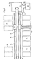
- Fig. 1 shows a series of bales 11, which are parked on a stand. Above these bales, a removal member 12 is arranged, which is carried by a carrier 13. A motor is provided in the carrier 13, by means of which the removal member 12 can be set in rotation. The carrier 13 is movable back and forth along rails 14. The removal member 12 is also adjustable in height. A conveying channel 15 serves to receive the flakes removed from the bales 11 by the removal roller 12 and to feed them to a storage unit 16. From the storage unit 16, the fiber flakes pass through a duct 17 to subsequent processing machines.
- a monitoring system 21 is located on the memory 16, which delivers a start signal a when a predetermined, minimum filling state of the memory 16 is reached and a stop signal e when a predetermined, maximum filling state of the memory 16 is reached.
- the signals a and e pass through an electrical line 22 to an electrical circuit 23, in which a monitoring signal y is generated, which leads to the carrier 13 via a line 24.
- the signal y is dependent on the time intervals present between the immediately successive start and stop signals a and e. 25 with a device is designated, which is used to deliver the longer cable length of the cable forming the line 24 required when the carrier 13 moves to the left, and which receives the cable which is released again when the carrier 13 moves to the right.
- the drawing shows the reference symbols for the signals on the lines through which they are transmitted.
- bales 18 are brought up and put down during the removal of the bales 11.
- the removal member 12 is pivoted through 180 ° about the axis of rotation 33, whereupon the removal of the row of bales 18 is started. After these have been removed, the removal member is pivoted back onto a new row of bales 11 and these are removed, etc.
- the circuit 23 shown in FIG. 1 comprises a switching arrangement 26 shown in FIG. 2, a line 27 and a computer 28.
- the memory 16 with the monitoring system 21, the channels 15 and 17 and the lines 22 and 24 are again shown .
- Flake material 32 is shown with oblique hatching.
- the removal machine 30 is represented as a unit schematically by a block.
- a nominal signal j is fed to the computer 28 through a line 31.
- the computer 28 forms a control signal s from the target signal j and the monitoring signal y supplied by the switching arrangement 26, which control signal s is fed via line 24 to a device (not shown) which controls the removal process of the removal member 12 and is present in the removal machine 30 or in the carrier 13 becomes.
- the start and stop signals a and e are fed directly from the monitoring system 21 to the removal machine 30 via the lines 22, 27 and 24.
- the carrier 13 moves back and forth with the removal member 12 on the rails 14.
- the flake material is removed from the bales 11 by the rotating removal member 12.
- This flock material 32 passes through the conveying channel 15 into the storage device 16.
- the amount of flake material 32 entering the storage 16 through the conveying channel 15 per unit time is somewhat larger than the amount of flake material 32 removed through the passage 17 per unit time.
- a working time interval T a and a downtime time interval T s connected to this are referred to as an operating cycle.
- a monitoring signal y is formed in the switching arrangement 26, which is dependent on the time intervals T a and T s , ie is a function of the variables T a and T s .
- the target signal j defines a predetermined, desired relationship of the values T a and T s to one another.
- T a and T s have to satisfy the relationship mentioned at the beginning, according to which in an operating cycle (of the duration (T a + T s )) the working time interval T a is four times the idle time interval T s (ie T a forms 80% and T s forms 20% of the duration of an operating cycle), the target signal j has a certain value.
- the signal y changes.
- the monitoring signal y and the desired signal j are compared with one another and a control signal s is generated which is a function of the deviation of the values T a and T s from their desired mutual relationship, which is predetermined by the signal j.
- This signal s controls the device provided in the removal machine 30 and controls the removal process of the removal member 12 in such a way that the flake production, ie the weight of the flakes removed by the removal member 12 per unit of time from the fiber bales 11 is changed in the sense that the desired relationship between T. and T s given by the target signal j is obtained.
- the control signal s effects at the transition of the removal from the upper to the middle region of the bale 11, for example by reducing the height adjustment of the removal member 12 per pass, i.e. per operating cycle, a reduction in weight of the flake material captured by the roller 12 per unit of time.
- the control signal s at the transition of the removal from the middle to the lower region of the bales 11, for example by increasing the height adjustment of the removal member 12 per pass causes an increase in the weight of the flake material recorded by the roller 12 per unit of time.
- Such a weight reduction or enlargement of the amount of flake material removed per unit of time is achieved not only by the reductions or enlargements of the reduction mentioned just before the passages of the removal member 12.
- the time intervals of the successive passages of the removal member 12 can also be reduced or enlarged.
- the weight of the flakes removed from the fiber bales 11 by the removal member 12 per unit of time is changed. If this weight is increased, the memory 16 is filled more quickly, so that the number of downtime intervals T s increases. If this weight is reduced, the number of these intervals T s is reduced.
- a monitoring signal y is formed in the switching arrangement 26, which is proportional to the expression T a / (T a + T s ).
- T a / (T a + T s ) has the value 0 , 8 owns.
- a control signal is formed in the computer 28 from the target signal j and the monitoring signal y, by means of which the removal machine 30 is adjusted to the mentioned value 0.8 by changing the amount of flakes removed per unit of time.
Description
Die vorliegende Erfindung bezieht sich auf ein Verfahren zum Abtragen von auf einer Standfläche abgestellten Faserballen in der Spinnerei, bei welchem ein Abtragsorgan über die Ballen hin und her bewegt und vor jedem Durchgang abgesenkt wird und die abgetragenen Flocken in einen Speicher eingefüllt und aus diesem zu ihrer nächsten Verarbeitungsstufe befördert werden, wobei gewichtsmässig die pro Zeiteinheit in den Speicher hinein beförderte Flockenmenge etwas grösser ist als die pro Zeiteinheit aus dem Speicher heraus beförderte Flockenmenge und wobei beim Erreichen eines maximalen Füllungszustandes des Speichers ein den Abtragsvorgang stillsetzendes Stoppsignal und beim Erreichen eines minimalen Füllungszustandes des Speichers ein den Abtragsvorgang in Betrieb setzendes Startsignal geliefert wird.The present invention relates to a method for removing fiber bales parked on a stand in the spinning mill, in which a removal member is moved back and forth over the bales and lowered before each pass, and the removed flakes are poured into a storage device and from there to the storage device are transported to the next processing stage, the weight of the amount of flakes transported into the storage unit per unit of time being somewhat greater than the amount of flakes transported out of the storage unit per unit of time, and when a maximum filling state of the storage unit is reached, a stop signal which stops the removal process and a minimum filling level of the A start signal which sets the removal process into operation is delivered.
Durch die Zeitschrift «Melliand Textilberichte 1/1982, S. 15» ist es bereits bekannt, Mikroelektronik in der Spinnereivorbereitung zum Abtasten der Höhen vorgelegter Ballen und zum Zustellen der vorgegebenen Abtragtiefe pro Ballengruppe, zu verwenden. Bei dieser bekannten Anordnung handelt es sich um eine Anlage zum Mischen verschiedener Fasern.Through the magazine "Melliand Textile Reports 1/1982, p. 15" it is already known to use microelectronics in spinning preparation for scanning the heights of bales and for delivering the specified removal depth per bale group. This known arrangement is a system for mixing different fibers.
Bei in der Praxis bekannten Einrichtungen zum Abtragen von Faserflocken von auf einer Standfläche abgestellten Faserballen wird das Abtragsorgan wiederholt über eine Reihe von Ballen geführt, wobei das vom Abtragsorgan erfasste Fasermaterial als Faserflocken frei und, beispielsweise durch einen Absaugkanal, laufend weggeführt wird. Dabei bewegt sich das Abtragsorgan mit konstanter Geschwindigkeit über die Ballen hinweg und wird nach jedem Durchgang um einen konstanten Betrag in ihrer Höheverstellt. Dadurch wird bei jedem Durchgang eine dieser Höhenverstellung entsprechende Schicht Flockenmaterial von den Ballen abgetragen. Das erfasste Flockenmaterial wird in einen Speicher befördert und gelangt von diesem zu den anschliessenden Verarbeitungsmachinen, wie Karden, Streckwerde und Kämmaschinen. Es ist erwünscht, dass diese nachfolgenden Verarbeitungsmaschinen ununterbrochen mit Material beliefert werden. Deshalb muss im Speicher stets Flockenmaterial vorhanden sein. Dies wird dadurch gewährleistet, dass dem Speicher etwas mehr Flockenmaterial zugeführt wird als die nachfolgenden Maschinen benötigen. Um ein Überfüllen des Speichers zu vermeiden, wird der Abtragungsvorgang jeweils abgestellt, wenn der Füllungszustand des Speichers einen maximalen Wert überschreitet. Wenn daraufhin der Füllungszustand im Speicher als Folge der steten Flocken - entnahme für die nachfolgenden Verarbeitungsmaschinen einen minimalen Wert unterschreitet, wird der Abtragungsvorgang wieder eingeschaltet. Dadurch ergibt sich ein periodisches Abstellen und Inbetriebsetzen des Abtragvorganges, d.h. der Flockenproduktion. Als optimale Arbeitsweise gilt eine solche, bei welcher der Abtragungsvorgang ungefähr 80-90% der Zeit arbeitet und ungefähr 20-10% der Zeit stillsteht. Diese Zeitreserve von 10-20% wird benötigt und genügt erfahrungsgemäss, um, unter anderem, anfallende Wartungsarbeiten durchzuführen, oder, bei einer Arbeitsweise mit zwei abwechslungsweise abzutragenden Ballenreihen, das Umdrehen des Abtragsorgans um 180° von der abgetragenen Ballenreihe auf die volle Ballenreihe, durchzuführen.In devices known in practice for the removal of fiber flakes from fiber bales placed on a standing surface, the removal member is repeatedly guided over a series of bales, the fiber material detected by the removal member being continuously removed as fiber flakes and, for example, through a suction channel. The removal device moves across the bales at a constant speed and its height is adjusted by a constant amount after each pass. As a result, a layer of flake material corresponding to this height adjustment is removed from the bales with each pass. The captured flake material is transported to a store and from there to the subsequent processing machines such as cards, stretchers and combing machines. It is desirable that these subsequent processing machines be continuously supplied with material. Therefore, flake material must always be present in the storage. This is ensured by the fact that a little more flake material is fed into the storage than the subsequent machines require. To avoid overfilling the storage, the removal process is stopped when the filling level of the storage exceeds a maximum value. If the filling level in the memory then drops below a minimum value as a result of the constant flake removal for the subsequent processing machines, the ablation process is switched on again. This results in periodic shutdown and commissioning of the removal process, i.e. of flake production. An optimal mode of operation is one in which the removal process works approximately 80-90% of the time and stands still approximately 20-10% of the time. This time reserve of 10-20% is required and experience has shown that it is sufficient, among other things, to carry out maintenance work or, when working with two alternate rows of bales, turning the removal device 180 ° from the removed row of bales to the full row of bales .
Die abzutragenden Ballen sind - verteilt auf die Höhe - nicht überall gleich dicht. Sie sind in ihrem mittleren Bereich am dichtesten. Dadurch ergibt sich, dass beim Abtragen des obersten und untersten Teiles einer Balle gewichtsmässig weniger Flocken geliefert werden als beim Abtragen des mittleren Teiles derselben. Bezüglich der im vorherigen gemachten Ausführungen bedeutet das, dass am Anfang und am Schluss der Ballen dem Speicher pro Zeiteinheit gewichtsmässig weniger Material zugeführt wird als beim Abtragen im Mittelbereich der Ballen. Somit arbeitet die Abtragsmaschine am Anfang und Ende der Ballen für längere Zeitperioden als dies beim Abtragen des Mittelbereiches der Ballen der Fall ist.The bales to be removed are not equally dense across the board. They are the densest in their central area. This means that when the top and bottom parts of a bale are removed, less flakes are delivered in terms of weight than when the middle part is removed. With regard to the statements made above, this means that at the beginning and at the end of the bale less material is fed to the storage unit per unit of time in weight than when the bale is removed in the central region. Thus, the removal machine works at the beginning and end of the bale for longer periods of time than when removing the central area of the bale.
Um bei den bekannten Einrichtungen eine ununterbrochene Lieferung von Flocken aus dem Speicher zu gewährleisten, wird am Anfang und Ende der Ballen der optimale Stillstandswert von 10-20% der Betriebszeit vorgesehen. Damit werden die Stillstände der Abtragswalze beim Abtragen des Mittelbereichs der Ballen zu lang. Dies ist unökonomisch, weil dadurch die Putzereimaschinen nur ungenügend ausgenützt sind.In order to ensure an uninterrupted delivery of flakes from the storage in the known devices, the optimal standstill value of 10-20% of the operating time is provided at the beginning and end of the bale. As a result, the downtimes of the removal roller when removing the central area of the bale become too long. This is uneconomical because it means that the blowroom machines are underused.
Dieser Nachteil soll durch die vorliegende Erfindung vermieden werden. Diese ist dadurch gekennzeichnet, dass die Start- und Stoppsignale einer Schaltanordnung zugeführt werden, welche ein Überwachungssignal erzeugt, welches von der Dauer der durch die Start- und Stoppsignale gegebenen Zeitintervalle abhängig ist und zusammen mit einem vorgegebene Zeitintervalle definierenden Sollsignal einem Rechner zugeführt wird, in welchem ein von dem Überwachungs- und dem Sollsignal abhängiges Steuersignal gebildet wird, welches zum Steuern des Gewichtes der durch das Abtragsorgan pro Zeiteinheit von den Faserballen abgetragenen Flocken einer den Abtragsvorgang des Abtragsorgans steuernden Einrichtung zugeführt wird.This disadvantage is to be avoided by the present invention. This is characterized in that the start and stop signals are fed to a switching arrangement which generates a monitoring signal which is dependent on the duration of the time intervals given by the start and stop signals and is fed to a computer together with a predetermined signal defining a predetermined time interval which forms a control signal which is dependent on the monitoring signal and the desired signal and which is fed to control the weight of the flakes removed from the fiber bale by the removal member per unit of time to a device controlling the removal process of the removal member.
Gemäss der Erfindung erfolgt somit das Abtragen des dichten Teils der Ballen, welcher den grössten Teil des Flockenmaterials der Ballen bildet, in relativ dünnen Schichten. Dies bedeutet ein schonenderes Ballenöffnen mit kleineren Flocken. Der Einfluss der Inhomogenität der Ballen wird praktisch eliminiert. Andererseits kann die laufende Anpassung an die optimalen Stillstandszeiten im Vergleich zu den bekannten Abtragsmaschinen und bei einer Flockenqualität, welche der mit diesen bekannten Maschinen erreichten gleich ist, zur Erhöhung der Gesamtproduktion der Abtragsmaschine benützt werden.According to the invention, the removal of the dense part of the bale, which forms the majority of the flake material of the bale, takes place in relatively thin layers. This means a more gentle bale opening with smaller flakes. The influence of the inhomogeneity of the bales is practically eliminated. On the other hand, the ongoing adaptation to the optimal downtimes in comparison to the known removal machines and with a flake quality which is the same as that achieved with these known machines can be used to increase the overall production of the removal machine.
Im folgenden sei die Erfindung anhand eines Ausführungsbeispiels und der Zeichnung näher erläutert. In der letzteren ist
- Fig. 1 eine Ansicht einer Ballenabtragseinrichtung mitzwei Ballenreihen, von oben gesehen und
- Fig. 2 eine schematische Darstellung einer Steuerung gemäss der Erfindung.
- Fig. 1 is a view of a bale removal device with two rows of bales, seen from above and
- Fig. 2 is a schematic representation of a controller according to the invention.
Die Fig. 1 zeigt eine Reihe von Ballen 11, welche auf einer Standfläche abgestellt sind. Über diesen Ballen ist ein Abtragsorgan 12 angeordnet, welches von einem Träger 13 getragen ist. Im Träger 13 ist ein Motor vorgesehen, durch welchen das Abtragsorgan 12 in Rotation versetzt werden kann. Der Träger 13 ist längs Schienen 14 hin und her bewegbar. Das Abtragsorgan 12 ist ausserdem in seiner Höhe verstellbar. Ein Förderkanal 15 dient zur Aufnahme der durch die Abtragungswalze 12 von den Ballen 11 abgetragenen Flocken und zum Zuführen derselben zu einem Speicher 16. Vom Speicher 16 gelangen die Faserflocken durch einen Kanal 17 zu anschliessenden Verarbeitungsmaschinen.Fig. 1 shows a series of
Am Speicher 16 befindet sich eine Überwachungsanlage 21, welche beim Erreichen eines vorgegebenen, minimalen Füllungszustandes des Speichers 16 ein Startsignal a und beim Erreichen eines vorgegebenen, maximalen Füllungszustandes des Speichers 16 ein Stoppsignal e liefert. Die Signale a und e gelangen über eine elektrische Leitung 22 zu einem elektrischen Schaltkreis 23. In diesem wird ein Überwachungssignal y erzeugt, welches über eine Leitung 24 zum Träger 13 führt. Das Signal y ist von den zwischen den unmittelbar aufeinanderfolgenden Start- und Stoppsignalen a bzw. e vorhandenen Zeitintervallen, abhängig. Mit 25 ist eine Einrichtung bezeichnet, welche zum Liefern der bei einer Bewegung des Trägers 13 nach links benötigten, grössern Kabellänge des die Leitung 24 bildenden Kabels dient, und welche bei einer Bewegung des Trägers 13 nach rechts das frei werdende Kabel wieder aufnimmt. In der Zeichnung sind die Bezugszeichen für die Signale an den Leitungen aufgeführt, durch welche sie übertragen werden.A
In Fig. 1 ist eine zweite Reihe strichliniert gezeichneter Ballen 18 gezeigt. In einer solchen Ausführungsform werden während des Abtragens der Ballen 11 die Ballen 18 herangeführt und abgestellt. Nachem die Ballen 11 abgetragen sind, wird das Abtragungsorgan 12 um 180° um die Drehachse 33 geschwenkt, worauf das Abtragen der Reihe der Ballen 18 aufgenommen wird. Nachdem diese abgetragen sind, wird das Abtragungsorgan wieder auf eine neue Reihe von Ballen 11 zurückgeschwenkt und diese werden abgetragen usw.1 shows a second row of
Der in Fig. 1 dargestellte Schaltkreis 23 umfasst eine in Fig. 2 gezeigte Schaltanordnung 26, eine Leitung 27 und einen Rechner 28. Im weiteren sind wiederum der Speicher 16 mit der Überwachungsanlage 21, die Kanäle 15 und 17 und die Leitungen 22 und 24 gezeigt. Mit schräger Schraffur ist Flockenmaterial 32 dargestellt. Die Abtragsmaschine 30 ist als eine Einheit schematisch durch einen Block dargestellt. Durch eine Leitung 31 wird dem Rechner 28 ein Sollsignal j zugeführt.The
Dieses legt die Dauer der Zeitintervalle fest, während denen sich die Abtragsmaschine 30 im Arbeitszustand und im Stillstand d.h. in einem keine Flocken produzierenden Zustand, befindet. Der Rechner 28 bildet aus dem Sollsignal j und dem von der Schaltanordnung 26 gelieferten Überwachungssignal y ein Steuersignal s, welches über die Leitung 24 einer in der Abtragsmaschine 30 bzw. im Träger 13 vorhandenen, den Abtragsvorgang des Abtragsorgans 12 steuernden Einrichtung (nicht gezeigt) zugeführt wird. Zusätzlich werden die Start- und Stoppsignale a bzw. e von der Überwachungsanlage 21 über die Leitungen 22, 27 und 24 der Abtragsmaschine 30 direktzugeführt.This determines the duration of the time intervals during which the
Im Betrieb fährt der Träger 13 mit dem Abtragsorgan 12 auf den Schienen 14 hin und her. Dabei wird durch das rotierende Abtragsorgan 12 Flokkenmaterial von den Ballen 11 weggenommen. Dieses Flockenmaterial 32 gelangt durch den Förderkanal 15 in den Speicher 16. Nach jedem Durchgang des Abtragsorgans 12 wird diese um einen bestimmmten Betrag abgesenkt, so dass sie bei jedem Durchgang eine Schicht Fasermaterial abträgt, dessen Dicke dem Betrag, um den das Abtragsorgan 12 abgesenkt wurde, gleich ist. Wie eingangs erwähnt, ist die pro Zeiteinheit in den Speicher 16 durch den Förderkanal 15 einlaufende Menge von Flockenmaterial 32 etwas grösser als pro Zeiteinheit die durch den Kanal 17 entnommene Menge von Flockenmaterial 32. Sobald im Speicher 16 ein vorgegebener, maximaler Füllungszustand erreicht wird, liefert die Überwachungsanlage 21 ein Stoppsignal e.In operation, the
Dieses gelangt über die Leitungen 22, 27 und 24 unmittelbar zur Abtragsmaschine 30 und bewirkt ein Anhalten der Flockenproduktion bzw. des Abtragsvorgangs. Währenddessen dauert die Entnahme von Flockenmaterial 32 aus dem Speicher 16 an. Beim Erreichen eines vorgegebenen, minimalen Füllungszustandes des Speichers 16 wird von der Überwachungsanlage 21 ein Startsignal a abgegeben. Dieses gelangt, ebenso wie das Stoppsignal e, über die Leitungen 22, 27 und 24 direkt zur Abtragsmaschine 30 und bewirkt ein Wieder-in-Bewegung-Setzen derselben.This passes directly to the
Im normalen Betrieb der Abtragsmaschine 30 sind von jedem Füllungszustande a bis zum unmittelbar darauffolgenden Stoppsignal e dauernde Arbeitszeitintervalle Ta und von jedem Stoppsignal e bis zum unmittelbar darauffolgenden Füllungszustande a dauernde Stillstandszeitintervalle Ts vorhanden. Ein Arbeitszeitintervall Ta und ein an dieses angeschlossenes Stillstandszeitintervall Ts seien als ein Betriebszyklus bezeichnet. In der Schaltanordnung 26 wird ein Überwachungssignal y gebildet, welches von den Zeitintervallen Ta und Ts abhängig ist, d.h. eine Funktion der Grössen Ta und Ts ist. Das Sollsignal j definiert eine vorgegebene, gewünschte Beziehung der Werte Ta und Ts zueinander. Falls Ta und Ts die eingangs erwähnte Beziehung erfüllen müssen, gemäss welcher in einem Betriebszyklus (von der Dauer (Ta+Ts)) das Arbeitszeitintervall Ta das vierfache des Stillstandszeitintervalles Ts ist (d.h. Ta bildet z.B. 80% und Ts bildet 20% der Zeitdauer eines Betriebszyklus), so weist das Sollsignal j einen bestimmten Wert auf. Mit einer Veränderung der von der Überwachungsanlage 21 gelieferten Werte von Ta in bezug auf Ts verändert sich das Signal y.In normal operation of the
Im Rechner 28 werden das Überwachungssignal y und das Sollsignal j miteinander verglichen und ein Steuersignal s erzeugt, welches eine Funktion der Abweichung der Werte Ta und Ts von ihrer gewünschten, durch das Signal j vorgegebenen, gegenseitigen Beziehung ist. Dieses Signal s steuert die in der Abtragsmaschine 30 vorgesehene, den Abtragsvorgang des Abtragsorgans 12 steuernde Einrichtung in der Weise, dass die Flokkenproduktion, d.h. dass das Gewicht der durch das Abtragsorgan 12 pro Zeiteinheit von den Faserballen 11 abgetragenen Flocken in dem Sinne verändert wird, dass die gewünschte, durch das Sollsignal j gegebene Beziehung von T. und Ts erhalten wird.In the
Erfindungsgemäss bewirkt das Steuersignal s beim Übergang des Abtragens vom oberen zum mittleren Bereich der Ballen 11, durch beispielsweise eine Verkleinerung der Höhenverstellung desAbtragsorgans 12 pro Durchgang, d.h. pro Betriebszyklus, eine gewichtsmässige Verkleinerung des pro Zeiteinheit von der Walze 12 erfassten Flockenmaterials. Entsprechend bewirkt das Steuersignal s beim Übergang des Abtragens vom mittleren zum unteren Bereich der Ballen 11, durch beispielsweise eine Vergrösserung der Höhenverstellung des Abtragsorgans 12 pro Durchgang, eine gewichtsmässige Vergrösserung des pro Zeiteinheit von der Walze 12 erfassten Flockenmaterials.According to the invention, the control signal s effects at the transition of the removal from the upper to the middle region of the
Eine solche gewichtsmässige Verkleinerung bzw. Vergrösserung der pro Zeiteinheit abgetragenen Menge von Flockenmaterial wird nicht nur durch die soeben erwähnten, vor den Durchgängen des Abtragsorgans 12 erfolgenden Verkleinerungen bzw. Vergrösserungen der Absenkung erreicht. Anstelle einer Vergrösserung oder Verkleinerung der Absenkung können z.B. auch die zeitlichen Abstände der aufeinanderfolgenden Durchgänge des Abtragsorgans 12 verkleinert bzw. vergrössert werden. Dabei bildet die Veränderung der Durchgangszeit des sich durchbewegenden Abtragsorgans 12, z.B. durch Änderung der Fahrgeschwindigkeit des Trägers 13, eine Variationsmöglichkeit.Such a weight reduction or enlargement of the amount of flake material removed per unit of time is achieved not only by the reductions or enlargements of the reduction mentioned just before the passages of the removal member 12. Instead of increasing or decreasing the reduction, e.g. the time intervals of the successive passages of the removal member 12 can also be reduced or enlarged. The change in the transit time of the moving removal member 12, e.g. by changing the driving speed of the
Durch das Regulieren der Abtragsmaschine 30 mittels des Steuersignales s wird, wie bereits erwähnt, das Gewicht der durch das Abtragsorgan 12 pro Zeiteinheitvon den Faserballen 11 abgetragenen Flocken verändert. Wird dieses Gewicht vergrössert, so wird der Speicher 16 rascher gefüllt, so dass die Zahl der Stillstandszeitintervalle Ts zunimmt. Wird dieses Gewicht verkleinert, so wird die Zahl dieser Intervalle Ts verkleinert.By regulating the
In einer speziellen Ausführungsform der Erfindung wird in der Schaltanordnung 26 ein Überwachungssignal y gebildet, welches zum Ausdruck Ta/(Ta+Ts) proportional ist. Dies bedeutet, dass unter den speziellen Bedingungen, bei welchen im Betrieb der Abtragsmaschine 30 die Arbeitszeitintervalle Ta 80% und die Stillstandszeitintervalle Ts 20% der Zeitdauer eines Betriebszyklus betragen, der Ausdruck Ta/(Ta+Ts) den Wert 0,8 besitzt. In einem solchen Fall wird im Rechner 28 aus dem Sollsignal j und dem Überwachungssignal y ein Steuersignal gebildet, durch welches die Abtragsmaschine 30 durch Verändern der pro Zeiteinheit abgetragenen Flockenmenge auf den genannten Wert 0,8 einreguliert wird. Die Verwendung des Ausdrucks Ta/(Ta+Ts) als Basis für die Bildung des Steuersignals ergibt den Vorteil einer einfachen und zuverlässig arbeitenden Schaltung.In a special embodiment of the invention, a monitoring signal y is formed in the switching
Claims (6)
Applications Claiming Priority (2)
| Application Number | Priority Date | Filing Date | Title |
|---|---|---|---|
| CH2719/82 | 1982-05-04 | ||
| CH271982 | 1982-05-04 |
Publications (2)
| Publication Number | Publication Date |
|---|---|
| EP0093235A1 EP0093235A1 (en) | 1983-11-09 |
| EP0093235B1 true EP0093235B1 (en) | 1985-07-03 |
Family
ID=4240059
Family Applications (1)
| Application Number | Title | Priority Date | Filing Date |
|---|---|---|---|
| EP83101465A Expired EP0093235B1 (en) | 1982-05-04 | 1983-02-16 | Method of opening fibre bales |
Country Status (4)
| Country | Link |
|---|---|
| US (1) | US4566152A (en) |
| EP (1) | EP0093235B1 (en) |
| JP (1) | JPS58191225A (en) |
| DE (1) | DE3360334D1 (en) |
Families Citing this family (7)
| Publication number | Priority date | Publication date | Assignee | Title |
|---|---|---|---|---|
| DE3513295C2 (en) * | 1985-04-13 | 1998-05-14 | Truetzschler Gmbh & Co Kg | Device for removing bales of fiber |
| GB8520130D0 (en) * | 1985-08-10 | 1985-09-18 | Haigh Chadwick Ltd | Control apparatus |
| GB8524304D0 (en) * | 1985-10-02 | 1985-11-06 | Rieter Ag Maschf | Flock delivery systems |
| EP0312805B1 (en) * | 1987-10-07 | 1991-11-21 | Maschinenfabrik Rieter Ag | Production control |
| EP0386580A1 (en) * | 1989-03-07 | 1990-09-12 | Maschinenfabrik Rieter Ag | Method and apparatus for removing flocks from fiber bales |
| EP0548023A1 (en) * | 1991-12-17 | 1993-06-23 | Maschinenfabrik Rieter Ag | Flow control of a blow room line |
| ITMI20040412A1 (en) * | 2004-03-04 | 2004-06-04 | Marzoli Spa | DEVICE AND PROCEDURE FOR THE AUTOMATIC COLLECTION OF FIBERS FROM FIBER BALES |
Family Cites Families (8)
| Publication number | Priority date | Publication date | Assignee | Title |
|---|---|---|---|---|
| US4176995A (en) * | 1972-10-05 | 1979-12-04 | Fiber Controls Corporation | Automatic pickup and unloading crane |
| US3951282A (en) * | 1973-10-24 | 1976-04-20 | Alex Jacques Keller | Method for feeding fibers |
| DE2626648C2 (en) * | 1976-06-15 | 1978-07-27 | Schubert & Salzer Maschinenfabrik Ag, 8070 Ingolstadt | Device for opening and mixing fiber bales |
| US4087882A (en) * | 1977-01-12 | 1978-05-09 | Automatic Material Handling, Inc. | Apparatus for plucking and delivering fiber to a feeder with automatic dust control |
| DE2832085C3 (en) * | 1978-07-21 | 1981-08-13 | Trützschler GmbH & Co KG, 4050 Mönchengladbach | Method and device for assembling fiber blends |
| US4363585A (en) * | 1979-09-25 | 1982-12-14 | Automatic Material Handling, Inc. | Bale level control system for mechanical hopper feeder |
| DE2939890C3 (en) * | 1979-10-02 | 1982-02-25 | Schubert & Salzer Maschinenfabrik Ag, 8070 Ingolstadt | Method and device for opening and mixing fiber bales |
| ATE13448T1 (en) * | 1980-07-23 | 1985-06-15 | Rieter Ag Maschf | METHOD FOR MONITORING A MIXING PLANT FOR TEXTILE STAPLE FIBERS AND DEVICE FOR PERFORMING THESE. |
-
1983
- 1983-02-16 EP EP83101465A patent/EP0093235B1/en not_active Expired
- 1983-02-16 DE DE8383101465T patent/DE3360334D1/en not_active Expired
- 1983-04-12 US US06/484,421 patent/US4566152A/en not_active Expired - Fee Related
- 1983-04-19 JP JP58067894A patent/JPS58191225A/en active Granted
Also Published As
| Publication number | Publication date |
|---|---|
| JPH0321649B2 (en) | 1991-03-25 |
| EP0093235A1 (en) | 1983-11-09 |
| US4566152A (en) | 1986-01-28 |
| JPS58191225A (en) | 1983-11-08 |
| DE3360334D1 (en) | 1985-08-08 |
Similar Documents
| Publication | Publication Date | Title |
|---|---|---|
| DE3513295C2 (en) | Device for removing bales of fiber | |
| CH658261A5 (en) | Method and device for feeding, weighing and deliver a fibre quantity. | |
| DE3530905C2 (en) | ||
| CH659663A5 (en) | METHOD AND DEVICE FOR CONTROLLING AND REGULATING THE MACHINES OF A SPINNING PREPARATION PLANT. | |
| EP0311831B1 (en) | Control of working stages of a fibre processing plant | |
| CH671241A5 (en) | ||
| DE2436096A1 (en) | METHOD AND SYSTEM FOR THE PRODUCTION OF MIXED, SPINNABLE FIBER MATERIALS | |
| EP0799916A2 (en) | Combing machine with a controlled draw frame | |
| DE2605978C2 (en) | Device for controlling the piecing process in rotor spinning machines | |
| DE3617526A1 (en) | METHOD AND DEVICE FOR SUPPLYING A NUMBER OF CARDS, CRAWLS OR THE LIKE | |
| DE102007018536B4 (en) | Open-end spinning machine | |
| EP0093235B1 (en) | Method of opening fibre bales | |
| EP1009870B2 (en) | Regulated drawing frame | |
| DE102007043417B4 (en) | Open-end spinning machine | |
| DE3244619C2 (en) | Device for controlling a spinning preparation plant consisting of several sections | |
| CH659491A5 (en) | METHOD AND DEVICE FOR CONTROLLING THE TENSING PROCESS IN AN OPEN-END ROTOR SPINDING MACHINE. | |
| DE102015122391A1 (en) | A method of controlling a piecing process for re-spinning a yarn on a spinning machine | |
| EP0291710B1 (en) | Method and apparatus for controlling pieced yarn in an open-end spinning unit | |
| EP1917388A1 (en) | Flock supply system. | |
| EP1749907B1 (en) | Method for controlling the draft in a drafting area of a textile machine, and the textile machine | |
| DE2909133A1 (en) | DISTRIBUTOR FOR A CIGARETTE MAKING MACHINE | |
| DE2555181A1 (en) | DEVICE FOR DISTRIBUTION OF AVIVAGE AGENT ON THE THREAD DURING TWISTING | |
| EP0176809B1 (en) | Circular knitting machine for making high-pile knitwear | |
| DE112014000816T5 (en) | A method of controlling the warping of a fibrous web in a carding machine | |
| EP0177778B1 (en) | Method and circular knitting machine for making high-pile knitwear |
Legal Events
| Date | Code | Title | Description |
|---|---|---|---|
| PUAI | Public reference made under article 153(3) epc to a published international application that has entered the european phase |
Free format text: ORIGINAL CODE: 0009012 |
|
| AK | Designated contracting states |
Designated state(s): CH DE FR GB IT LI |
|
| 17P | Request for examination filed |
Effective date: 19831215 |
|
| ITF | It: translation for a ep patent filed |
Owner name: GUZZI E RAVIZZA S.R.L. |
|
| GRAA | (expected) grant |
Free format text: ORIGINAL CODE: 0009210 |
|
| AK | Designated contracting states |
Designated state(s): CH DE FR GB IT LI |
|
| REF | Corresponds to: |
Ref document number: 3360334 Country of ref document: DE Date of ref document: 19850808 |
|
| ET | Fr: translation filed | ||
| PLBE | No opposition filed within time limit |
Free format text: ORIGINAL CODE: 0009261 |
|
| STAA | Information on the status of an ep patent application or granted ep patent |
Free format text: STATUS: NO OPPOSITION FILED WITHIN TIME LIMIT |
|
| 26N | No opposition filed | ||
| PGFP | Annual fee paid to national office [announced via postgrant information from national office to epo] |
Ref country code: GB Payment date: 19930113 Year of fee payment: 11 Ref country code: DE Payment date: 19930113 Year of fee payment: 11 Ref country code: CH Payment date: 19930113 Year of fee payment: 11 |
|
| PGFP | Annual fee paid to national office [announced via postgrant information from national office to epo] |
Ref country code: FR Payment date: 19930120 Year of fee payment: 11 |
|
| ITTA | It: last paid annual fee | ||
| PG25 | Lapsed in a contracting state [announced via postgrant information from national office to epo] |
Ref country code: GB Effective date: 19940216 |
|
| PG25 | Lapsed in a contracting state [announced via postgrant information from national office to epo] |
Ref country code: LI Effective date: 19940228 Ref country code: CH Effective date: 19940228 |
|
| GBPC | Gb: european patent ceased through non-payment of renewal fee |
Effective date: 19940216 |
|
| PG25 | Lapsed in a contracting state [announced via postgrant information from national office to epo] |
Ref country code: FR Effective date: 19941031 |
|
| REG | Reference to a national code |
Ref country code: CH Ref legal event code: PL |
|
| PG25 | Lapsed in a contracting state [announced via postgrant information from national office to epo] |
Ref country code: DE Effective date: 19941101 |
|
| REG | Reference to a national code |
Ref country code: FR Ref legal event code: ST |