EP0093090B1 - A closure for bottles and the like of the type including a breakable bottom reservoir to break during use - Google Patents
A closure for bottles and the like of the type including a breakable bottom reservoir to break during use Download PDFInfo
- Publication number
- EP0093090B1 EP0093090B1 EP19830830076 EP83830076A EP0093090B1 EP 0093090 B1 EP0093090 B1 EP 0093090B1 EP 19830830076 EP19830830076 EP 19830830076 EP 83830076 A EP83830076 A EP 83830076A EP 0093090 B1 EP0093090 B1 EP 0093090B1
- Authority
- EP
- European Patent Office
- Prior art keywords
- reservoir
- cap
- crown
- skirt
- closure
- Prior art date
- Legal status (The legal status is an assumption and is not a legal conclusion. Google has not performed a legal analysis and makes no representation as to the accuracy of the status listed.)
- Expired
Links
Images
Classifications
-
- B—PERFORMING OPERATIONS; TRANSPORTING
- B65—CONVEYING; PACKING; STORING; HANDLING THIN OR FILAMENTARY MATERIAL
- B65D—CONTAINERS FOR STORAGE OR TRANSPORT OF ARTICLES OR MATERIALS, e.g. BAGS, BARRELS, BOTTLES, BOXES, CANS, CARTONS, CRATES, DRUMS, JARS, TANKS, HOPPERS, FORWARDING CONTAINERS; ACCESSORIES, CLOSURES, OR FITTINGS THEREFOR; PACKAGING ELEMENTS; PACKAGES
- B65D51/00—Closures not otherwise provided for
- B65D51/24—Closures not otherwise provided for combined or co-operating with auxiliary devices for non-closing purposes
- B65D51/28—Closures not otherwise provided for combined or co-operating with auxiliary devices for non-closing purposes with auxiliary containers for additional articles or materials
- B65D51/2807—Closures not otherwise provided for combined or co-operating with auxiliary devices for non-closing purposes with auxiliary containers for additional articles or materials the closure presenting means for placing the additional articles or materials in contact with the main contents by acting on a part of the closure without removing the closure, e.g. by pushing down, pulling up, rotating or turning a part of the closure, or upon initial opening of the container
- B65D51/2814—Closures not otherwise provided for combined or co-operating with auxiliary devices for non-closing purposes with auxiliary containers for additional articles or materials the closure presenting means for placing the additional articles or materials in contact with the main contents by acting on a part of the closure without removing the closure, e.g. by pushing down, pulling up, rotating or turning a part of the closure, or upon initial opening of the container the additional article or materials being released by piercing, cutting or tearing an element enclosing it
Definitions
- This invention relates to a closure for bottles and the like, of the type including a reservoir housed within the bottle neck and containing a material, generally as a powder, which is allowed to drop into the liquid in the bottle by breakage of the bottom in said reservoir.
- the bottom breakage is effected by pressure exerted on the presser member of cylindrical shape, entering the reservoir by a slantwise cut end, this operation being carried out according to known techniques following the opening of a guarantee aluminum or also plastic crown-cap.
- a first disadvantage consists of the difficulty in removing an aluminum crown-cap rolled about the bottle neck, operation which very often causes wounds to the operator's hands and which cannot always be manually carried out.
- the cylindrically shaped presser member Upon removal of the guarantee crown-cap, the cylindrically shaped presser member is acted upon, which member will be in the following simply referred to as piercing plunger, for the breakage of the reservoir bottom in which it is housed.
- the reservoir content generally powdery material
- the reservoir content is then allowed to fall down into the bottle, mixing with the liquid material therein.
- the bottle inlet has to be freed, by removing said reservoir which together with the piercing plunger remains embedded within the bottle neck.
- This is also a difficult manual operation because of the poor available gripping and high seal or friction between the reservoir and bottle, so that the aid of mechanical means is often resorted to, such as for example a suitable tool acting as a lever between the respective contact edges of the bottle and reservoir inlet.
- a closure in accordance with the pre-characterising part of claim 1 is known from US-A-3802604 which discloses a plurality of embodiments of a closure for a container with a reservoir.
- the closure comprises an inner threaded cap surmounted by a cover cap provided with a piercing plunger and with a removable tear-strip which encircles the adjacent edge portion of the container and the inner cap.
- Such a closure is planned for not being removed from the container, as the mixture is dispensed through a dispensing spout.
- DE-A-2625175 discloses several embodiments of a closure, with a reservoir.
- the closure comprises a cap with a hollow cylinder and with a tear-strip.
- FR-A-1568362 discloses a complicated closure with reservoir, comprising two threaded caps.
- closure for bottles and the like is characterised by the features in the characterising part of claim 1.
- reference numeral 1 denotes a crown-cap closure preferably of plastic material, according to the present invention and including a reservoir 2 with breakable bottom 3 whch is accommodated within the neck of a bottle 4.
- Said reservoir 2, containing a generally powdery material which is allowed to fall down ⁇ into the liquid in said bottle 4 by piercing through of the bottom thereof, is of well known type and comprises a circumferentially continuous ridge 5 for interfering with the inner portion of the neck of said bottle 4, and an annular edge 6 overlapping the annular edge 7 of the bottle neck.
- said crown-cap 1 Internally of and coaxially therewith said crown-cap 1 has a preferably hollow piercing plunger 8, made in a unitary body with said crown-cap, having the free end 9 slantwise cut and housing in said reservoir 2.
- the crown-cap 1 comprises a skirt 10 having at its lower edge 11 an inner annular ridge 12 for engagement upon transitory elastic deformation with the bottle inlet edge, as shown in Figure 2.
- a tearing removable strip 15 as defined by two circumferential parallel weakening or breaking lines 16 and 17, a gripping tab or tongue 13 being provided for aiding in tearing.
- said tearing removable strip 15 is internally and at a suitable height provided with at least one continuous ridge 15' (or a plurality of discontinuous ridges) for abutment with the top portion of the annular edge 6 of the reservoir 2 and suitable to prevent the skirt 10 from vertically moving when a casual pressure is exerted on the top portion 14 of the crown-cap 1, and accordingly to prevent any accidental piercing of reservoir 2.
- the reservoir 2 Upon piercing (Figure 3), the reservoir 2 remains embedded within the crown-cap 2, both due to friction between the outer portion of the piercing plunger 8 and the inside of the reservoir, and due to friction between the edge 6 of said reservoir and the inner surface of the portion 19 of the skirt 10 of said crown-cap, so that the reservoir can be removed together with the crown-cap 1 from the bottle 4 by exerting a simultaneous tractive and torsional stress on said portion 19 of skirt 10 which is to this end provided as knurled.
- the removal of the reservoir 2 is greatly facilitated because of the substantial increase in gripping due to the top portion 19 of the skirt of the guarantee crown-cap.
- the useful height of the portion 19 of said skirt is preferably greater than or equal to the distance as vertically measured between the corners of the slantwise cut end 9 of the piercing plunger 8, and this to provide a nearly complete breakage of the bottom 3 of reservoir 2 and accordingly to facilitate the fall of the powdery material therein contained into the bottle 4.
Description
- This invention relates to a closure for bottles and the like, of the type including a reservoir housed within the bottle neck and containing a material, generally as a powder, which is allowed to drop into the liquid in the bottle by breakage of the bottom in said reservoir.
- The bottom breakage is effected by pressure exerted on the presser member of cylindrical shape, entering the reservoir by a slantwise cut end, this operation being carried out according to known techniques following the opening of a guarantee aluminum or also plastic crown-cap.
- In this known arrangement (DE-A-27 38 551), the presser member is made together with the reservoir, and the whole is placed on the bottle neck, the guarantee crown-cap being successively applied by rolling about said neck.
- However, such a closure has substantial disadvantages, some of which will be hereinafter illustrated.
- A first disadvantage consists of the difficulty in removing an aluminum crown-cap rolled about the bottle neck, operation which very often causes wounds to the operator's hands and which cannot always be manually carried out.
- Known plastic crown-caps, as used to this end, also require complicated operations for removal thereof, because of tending to remain entrapped about the bottle neck.
- Upon removal of the guarantee crown-cap, the cylindrically shaped presser member is acted upon, which member will be in the following simply referred to as piercing plunger, for the breakage of the reservoir bottom in which it is housed.
- The reservoir content, generally powdery material, is then allowed to fall down into the bottle, mixing with the liquid material therein. Thus, in order to use the mixture thereby obtained, the bottle inlet has to be freed, by removing said reservoir which together with the piercing plunger remains embedded within the bottle neck. This is also a difficult manual operation because of the poor available gripping and high seal or friction between the reservoir and bottle, so that the aid of mechanical means is often resorted to, such as for example a suitable tool acting as a lever between the respective contact edges of the bottle and reservoir inlet.
- A closure in accordance with the pre-characterising part of claim 1 is known from US-A-3802604 which discloses a plurality of embodiments of a closure for a container with a reservoir.
- The closure comprises an inner threaded cap surmounted by a cover cap provided with a piercing plunger and with a removable tear-strip which encircles the adjacent edge portion of the container and the inner cap.
- Such a closure is planned for not being removed from the container, as the mixture is dispensed through a dispensing spout.
- DE-A-2625175 discloses several embodiments of a closure, with a reservoir.
- In one of such embodiments, the closure comprises a cap with a hollow cylinder and with a tear-strip.
- In the use of the closure, the bottom of the reservoir has not to be broken.
- FR-A-1568362 discloses a complicated closure with reservoir, comprising two threaded caps.
- After having broken the bottom of the reservoir, only the outer cap has to be removed from the container.
- Therefore, it clearly appears that the above described known closures, as well as other closures which have not been herein mentioned for the sake of brevity, but which do not anyhow show substantial differences as to functionality from those shown, have a poor practicability and require quite complicated operations for the removal thereof.
- It is the object of the present invention to obviate the above mentioned disadvantages, by providing a closure for bottles and the like which on one hand is capable of offering safety against any possible casual tamperings, and on the other hand enables by simple and ready operations to pierce through the reservoir therein contained and remove the whole from the bottle to which it is applied.
- In order to achieve these objects, the closure for bottles and the like, according to the present invention is characterised by the features in the characterising part of claim 1.
- Further characteristics of a closure for bottles and the like according to the present invention will become apparent from the following description referred to a preferred embodiment thereof, as shown in the accompanying drawings, in which:
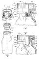
- Figure 1 is an exploded axonometric view with parts removed of a closure according to the present invention, showing the application thereof onto a bottle;
- Figure 2 is a front and partly cutaway view showing the closure of Figure 1 mounted on the bottle; and
- Figure 3 is a view showing the same closure with the median strip removed and the reservoir pierced through by the presser member.
- Referring to said figures of the accompanying drawings, reference numeral 1 denotes a crown-cap closure preferably of plastic material, according to the present invention and including a
reservoir 2 withbreakable bottom 3 whch is accommodated within the neck of abottle 4. Saidreservoir 2, containing a generally powdery material which is allowed to fall down·into the liquid in saidbottle 4 by piercing through of the bottom thereof, is of well known type and comprises a circumferentiallycontinuous ridge 5 for interfering with the inner portion of the neck of saidbottle 4, and anannular edge 6 overlapping theannular edge 7 of the bottle neck. - Internally of and coaxially therewith said crown-cap 1 has a preferably
hollow piercing plunger 8, made in a unitary body with said crown-cap, having thefree end 9 slantwise cut and housing in saidreservoir 2. - The crown-cap 1 comprises a skirt 10 having at its lower edge 11 an inner
annular ridge 12 for engagement upon transitory elastic deformation with the bottle inlet edge, as shown in Figure 2. - Of course, instead of said continuous
annular ridge 12, a discrete number of discontinuous ridges could be provided, still obtaining the same result, which is that to assure a seal between said crown-cap 1 andbottle 4. - At the middle portion of skirt 10, and preferably at a height from the top portion of the bottle inlet edge to beyond the top portion of the
annular edge 6 ofreservoir 2, there is provided a tearingremovable strip 15, as defined by two circumferential parallel weakening or breakinglines tongue 13 being provided for aiding in tearing. - According to a feature of the present invention, said tearing
removable strip 15 is internally and at a suitable height provided with at least one continuous ridge 15' (or a plurality of discontinuous ridges) for abutment with the top portion of theannular edge 6 of thereservoir 2 and suitable to prevent the skirt 10 from vertically moving when a casual pressure is exerted on thetop portion 14 of the crown-cap 1, and accordingly to prevent any accidental piercing ofreservoir 2. - The removal of said
median strip 15 provided the separation of thelower portion 18 from thetop portion 19 of the skirt 10 saidportion 18 remaining entrapped about the bottle neck, but falling down at its convex portion, so ad to facilitate the successive lowering of theportion 19 of said skirt for piercing through saidreservoir 2. Thus, upon removal ofsaid strip 15, a suitable pressure should only be exerted on thetop portion 14 of the crown-cap 1 to break thebreakable bottom 3 ofreservoir 2 by thepiercing plunger 8 which is integral with said crown cap, saidbottom 3 remaining attached for a short length to the sidewall of the reservoir at the top portion of the slantwise cut end of the piercing plunger, as shown in Figure 3. - Upon piercing (Figure 3), the
reservoir 2 remains embedded within the crown-cap 2, both due to friction between the outer portion of thepiercing plunger 8 and the inside of the reservoir, and due to friction between theedge 6 of said reservoir and the inner surface of theportion 19 of the skirt 10 of said crown-cap, so that the reservoir can be removed together with the crown-cap 1 from thebottle 4 by exerting a simultaneous tractive and torsional stress on saidportion 19 of skirt 10 which is to this end provided as knurled. Thus, the removal of thereservoir 2 is greatly facilitated because of the substantial increase in gripping due to thetop portion 19 of the skirt of the guarantee crown-cap. - It should be pointed out that the useful height of the
portion 19 of said skirt is preferably greater than or equal to the distance as vertically measured between the corners of the slantwisecut end 9 of thepiercing plunger 8, and this to provide a nearly complete breakage of thebottom 3 ofreservoir 2 and accordingly to facilitate the fall of the powdery material therein contained into thebottle 4. - Although in the figures of the accompanying drawings the lower edge 11 of the skirt 10 has been located immediately below the
annular edge 12, such a skirt 10 could be of course extended to bring said edge 11 in abutment with the convex portion ofbottle 4. - Of course, many changes in detail can be made to the crown-cap closure according to the present invention, without departing for this from the scope of the invention as claimed.
Claims (3)
Applications Claiming Priority (4)
| Application Number | Priority Date | Filing Date | Title |
|---|---|---|---|
| IT2166682U | 1982-04-23 | ||
| IT2166582U IT8221665V0 (en) | 1982-04-23 | 1982-04-23 | CLOSURE FOR BOTTLES AND SIMILAR OF THE TYPE CONTAINING AN AFONDO FRANGIBLE TANK. |
| IT2166582U | 1982-04-23 | ||
| IT2166682U IT8221666V0 (en) | 1982-04-23 | 1982-04-23 | CLOSURE FOR BOTTLES AND SIMILAR OF THE TYPE CONTAINING AN AFONDO FRANGIBLE TANK, TO BREAK DURING USE. |
Publications (3)
| Publication Number | Publication Date |
|---|---|
| EP0093090A2 EP0093090A2 (en) | 1983-11-02 |
| EP0093090A3 EP0093090A3 (en) | 1984-10-17 |
| EP0093090B1 true EP0093090B1 (en) | 1987-01-21 |
Family
ID=26327961
Family Applications (1)
| Application Number | Title | Priority Date | Filing Date |
|---|---|---|---|
| EP19830830076 Expired EP0093090B1 (en) | 1982-04-23 | 1983-04-06 | A closure for bottles and the like of the type including a breakable bottom reservoir to break during use |
Country Status (2)
| Country | Link |
|---|---|
| EP (1) | EP0093090B1 (en) |
| DE (1) | DE3369297D1 (en) |
Cited By (2)
| Publication number | Priority date | Publication date | Assignee | Title |
|---|---|---|---|---|
| WO2011147750A1 (en) | 2010-05-25 | 2011-12-01 | Raumedic Ag | Closure device for a container for dispensing a substance |
| WO2021082973A1 (en) * | 2019-10-30 | 2021-05-06 | 李红彪 | Rotating pulling-type storage lid |
Families Citing this family (16)
| Publication number | Priority date | Publication date | Assignee | Title |
|---|---|---|---|---|
| DE8502008U1 (en) * | 1985-01-26 | 1985-08-29 | Celamerck Gmbh & Co Kg, 6507 Ingelheim | Closure cap for two-component packs |
| IT1217761B (en) * | 1988-06-01 | 1990-03-30 | Dam Technological Research Ltd | TANK CAP FOR POWDERS |
| IT1259924B (en) * | 1992-03-19 | 1996-03-28 | Lameplast Srl | DROPPER BOTTLE PARTICULARLY FOR PHARMACEUTICAL PRODUCTS ACTIVATED FOR MIXING USE |
| FI102642B (en) * | 1996-06-19 | 1999-01-15 | Orion Diagnostica Oy | Plug for a reaction vessel or equivalent |
| DE19850934C2 (en) * | 1998-11-05 | 2001-07-12 | Lange Gmbh Dr Bruno | Closure element for closing, storing and introducing reagents and / or auxiliary substances into a reaction container |
| DE10245172A1 (en) | 2002-09-26 | 2004-04-01 | Boehringer Ingelheim International Gmbh | Two-component packaging unit |
| MXPA06001706A (en) | 2003-08-19 | 2006-05-19 | Boehringer Ingelheim Int | Multivitamin syrup for children or young adults. |
| US8215505B2 (en) | 2004-03-08 | 2012-07-10 | Lee Jeong-Min | Structure of cap having storage space |
| WO2005091730A2 (en) * | 2004-03-25 | 2005-10-06 | Jeong-Min Lee | Structure of cap having plural storing spaces |
| WO2005097615A1 (en) * | 2004-04-08 | 2005-10-20 | Jeong-Min Lee | Structure of cap having inner cap |
| KR200363704Y1 (en) * | 2004-07-01 | 2004-10-06 | 임효빈 | Cover assembly enable to mix interior material at opening |
| US8668400B2 (en) | 2007-04-05 | 2014-03-11 | The Hartz Mountain Corporation | Fluid applicator |
| US8109236B2 (en) | 2007-04-05 | 2012-02-07 | Sumitomo Corporation Of America | Fluid delivery assembly |
| EP2154081A1 (en) * | 2008-08-06 | 2010-02-17 | Merit 90 S.n.c. di Francesco Lamoure & C. | Closing device for medical containers and the like including a temporary receptacle |
| WO2011030280A1 (en) * | 2009-09-09 | 2011-03-17 | Andrew Homer Nathaniel | Dispenser |
| DE102012111374B3 (en) * | 2012-11-23 | 2014-03-20 | Andrea Krayenbühl | Dosing lid for metered delivery of substances e.g. nutrients e.g. carbohydrates, has threaded neck whose ring edge is formed at outer circumference of annular flange to bend radially inward in weakened cross-section area |
Family Cites Families (5)
| Publication number | Priority date | Publication date | Assignee | Title |
|---|---|---|---|---|
| FR1568362A (en) * | 1968-04-03 | 1969-05-23 | ||
| BE794915A (en) * | 1972-02-03 | 1973-08-02 | Inge Spa | CLOSING DEVICE FOR BOTTLES AND ANALOGUES, ALLOWING SEPARATE STORAGE OF INGREDIENTS TO BE MIXED AT THE TIME OF USE |
| US3802604A (en) * | 1972-02-28 | 1974-04-09 | Oreal | Device for storing two products separately and dispensing them simultaneously |
| DE2625175C3 (en) * | 1976-06-04 | 1981-01-15 | Friedrich Sanner Kg, 6140 Bensheim | Container closure with active ingredient chamber |
| IT1095010B (en) * | 1978-04-27 | 1985-08-10 | Sigma Tau Ind Farmaceuti | DEVICE SUITABLE FOR CONTAINING TWO PRODUCTS IN PARTICULAR MEDICINAL PRODUCTS, TO BE MIXED AT THE TIME OF USE |
-
1983
- 1983-04-06 EP EP19830830076 patent/EP0093090B1/en not_active Expired
- 1983-04-06 DE DE8383830076T patent/DE3369297D1/en not_active Expired
Cited By (3)
| Publication number | Priority date | Publication date | Assignee | Title |
|---|---|---|---|---|
| WO2011147750A1 (en) | 2010-05-25 | 2011-12-01 | Raumedic Ag | Closure device for a container for dispensing a substance |
| DE102010029259A1 (en) | 2010-05-25 | 2011-12-01 | Raumedic Ag | Closure device for a container for dispensing a substance |
| WO2021082973A1 (en) * | 2019-10-30 | 2021-05-06 | 李红彪 | Rotating pulling-type storage lid |
Also Published As
| Publication number | Publication date |
|---|---|
| DE3369297D1 (en) | 1987-02-26 |
| EP0093090A2 (en) | 1983-11-02 |
| EP0093090A3 (en) | 1984-10-17 |
Similar Documents
| Publication | Publication Date | Title |
|---|---|---|
| EP0093090B1 (en) | A closure for bottles and the like of the type including a breakable bottom reservoir to break during use | |
| EP0356758B1 (en) | Closure for bottles and the like, comprising a reservoir with a breakable bottom | |
| US5038951A (en) | Closure for monodose bottles and the like, comprising a reservoir provided with a breakable bottom | |
| US4779764A (en) | Pouring stopper | |
| US4281774A (en) | Tamper proof snap cap | |
| US3358865A (en) | Container closure | |
| US4583665A (en) | Combination container with membrane sealed finish and tamper-indicating dispensing closure | |
| USRE39867E1 (en) | Tamper-evident container closure | |
| US4746035A (en) | Liquid dispenser having a tamperproof overcap | |
| US3920141A (en) | Stopper for containers, especially bottles and flasks | |
| US3028992A (en) | Reusable tamper-indicating container closure | |
| KR100264898B1 (en) | Tamper-indacating plastic closure with pilfer band having staggerere scores | |
| US3013687A (en) | Closure for packages of biological products | |
| US4501372A (en) | Tear-open closure for a container | |
| US4602718A (en) | Dual-operation tamper-evident band for closures | |
| EP0244036A2 (en) | Pressure venting closure cap for a container spout | |
| US5114030A (en) | Tip off container cap with removable stem | |
| GB1409703A (en) | Anti-theft closure cap | |
| EP0243551A3 (en) | Cap and neck structure for a wide mouth jar | |
| US5709311A (en) | Method and apparatus for removing and storing a container seal | |
| USRE40003E1 (en) | Tamper-evident container closure | |
| US7581651B2 (en) | Metal pilfer-proof cap | |
| US3379326A (en) | Container closure | |
| AU625933B2 (en) | Bottle and cap closure system | |
| US5176279A (en) | Container cap |
Legal Events
| Date | Code | Title | Description |
|---|---|---|---|
| PUAI | Public reference made under article 153(3) epc to a published international application that has entered the european phase |
Free format text: ORIGINAL CODE: 0009012 |
|
| AK | Designated contracting states |
Designated state(s): BE CH DE FR GB LI NL SE |
|
| PUAL | Search report despatched |
Free format text: ORIGINAL CODE: 0009013 |
|
| AK | Designated contracting states |
Designated state(s): BE CH DE FR GB LI NL SE |
|
| 17P | Request for examination filed |
Effective date: 19850417 |
|
| GRAA | (expected) grant |
Free format text: ORIGINAL CODE: 0009210 |
|
| AK | Designated contracting states |
Kind code of ref document: B1 Designated state(s): BE CH DE FR GB LI NL SE |
|
| ET | Fr: translation filed | ||
| REF | Corresponds to: |
Ref document number: 3369297 Country of ref document: DE Date of ref document: 19870226 |
|
| PLBE | No opposition filed within time limit |
Free format text: ORIGINAL CODE: 0009261 |
|
| STAA | Information on the status of an ep patent application or granted ep patent |
Free format text: STATUS: NO OPPOSITION FILED WITHIN TIME LIMIT |
|
| 26N | No opposition filed | ||
| PGFP | Annual fee paid to national office [announced via postgrant information from national office to epo] |
Ref country code: FR Payment date: 19910214 Year of fee payment: 9 |
|
| PGFP | Annual fee paid to national office [announced via postgrant information from national office to epo] |
Ref country code: SE Payment date: 19910218 Year of fee payment: 9 |
|
| PGFP | Annual fee paid to national office [announced via postgrant information from national office to epo] |
Ref country code: CH Payment date: 19910225 Year of fee payment: 9 |
|
| PGFP | Annual fee paid to national office [announced via postgrant information from national office to epo] |
Ref country code: BE Payment date: 19910228 Year of fee payment: 9 |
|
| PGFP | Annual fee paid to national office [announced via postgrant information from national office to epo] |
Ref country code: GB Payment date: 19910405 Year of fee payment: 9 |
|
| PGFP | Annual fee paid to national office [announced via postgrant information from national office to epo] |
Ref country code: NL Payment date: 19910430 Year of fee payment: 9 |
|
| PGFP | Annual fee paid to national office [announced via postgrant information from national office to epo] |
Ref country code: DE Payment date: 19910628 Year of fee payment: 9 |
|
| PG25 | Lapsed in a contracting state [announced via postgrant information from national office to epo] |
Ref country code: GB Effective date: 19920406 |
|
| PG25 | Lapsed in a contracting state [announced via postgrant information from national office to epo] |
Ref country code: SE Effective date: 19920407 |
|
| PG25 | Lapsed in a contracting state [announced via postgrant information from national office to epo] |
Ref country code: LI Effective date: 19920430 Ref country code: CH Effective date: 19920430 Ref country code: BE Effective date: 19920430 |
|
| BERE | Be: lapsed |
Owner name: CAPSULIT S.R.L. Effective date: 19920430 |
|
| PG25 | Lapsed in a contracting state [announced via postgrant information from national office to epo] |
Ref country code: NL Effective date: 19921101 |
|
| GBPC | Gb: european patent ceased through non-payment of renewal fee | ||
| NLV4 | Nl: lapsed or anulled due to non-payment of the annual fee | ||
| PG25 | Lapsed in a contracting state [announced via postgrant information from national office to epo] |
Ref country code: FR Effective date: 19921230 |
|
| REG | Reference to a national code |
Ref country code: CH Ref legal event code: PL |
|
| PG25 | Lapsed in a contracting state [announced via postgrant information from national office to epo] |
Ref country code: DE Effective date: 19930101 |
|
| REG | Reference to a national code |
Ref country code: FR Ref legal event code: ST |
|
| EUG | Se: european patent has lapsed |
Ref document number: 83830076.2 Effective date: 19921108 |