EP0093072A2 - A pneumatic tire - Google Patents
A pneumatic tire Download PDFInfo
- Publication number
- EP0093072A2 EP0093072A2 EP83630068A EP83630068A EP0093072A2 EP 0093072 A2 EP0093072 A2 EP 0093072A2 EP 83630068 A EP83630068 A EP 83630068A EP 83630068 A EP83630068 A EP 83630068A EP 0093072 A2 EP0093072 A2 EP 0093072A2
- Authority
- EP
- European Patent Office
- Prior art keywords
- tire
- rib
- portions
- footprint
- tread
- Prior art date
- Legal status (The legal status is an assumption and is not a legal conclusion. Google has not performed a legal analysis and makes no representation as to the accuracy of the status listed.)
- Granted
Links
Images


Classifications
-
- B—PERFORMING OPERATIONS; TRANSPORTING
- B60—VEHICLES IN GENERAL
- B60C—VEHICLE TYRES; TYRE INFLATION; TYRE CHANGING; CONNECTING VALVES TO INFLATABLE ELASTIC BODIES IN GENERAL; DEVICES OR ARRANGEMENTS RELATED TO TYRES
- B60C11/00—Tyre tread bands; Tread patterns; Anti-skid inserts
- B60C11/03—Tread patterns
- B60C11/0327—Tread patterns characterised by special properties of the tread pattern
- B60C11/0332—Tread patterns characterised by special properties of the tread pattern by the footprint-ground contacting area of the tyre tread
-
- B—PERFORMING OPERATIONS; TRANSPORTING
- B60—VEHICLES IN GENERAL
- B60C—VEHICLE TYRES; TYRE INFLATION; TYRE CHANGING; CONNECTING VALVES TO INFLATABLE ELASTIC BODIES IN GENERAL; DEVICES OR ARRANGEMENTS RELATED TO TYRES
- B60C11/00—Tyre tread bands; Tread patterns; Anti-skid inserts
- B60C11/03—Tread patterns
- B60C11/0306—Patterns comprising block rows or discontinuous ribs
-
- B—PERFORMING OPERATIONS; TRANSPORTING
- B60—VEHICLES IN GENERAL
- B60C—VEHICLE TYRES; TYRE INFLATION; TYRE CHANGING; CONNECTING VALVES TO INFLATABLE ELASTIC BODIES IN GENERAL; DEVICES OR ARRANGEMENTS RELATED TO TYRES
- B60C11/00—Tyre tread bands; Tread patterns; Anti-skid inserts
- B60C11/03—Tread patterns
- B60C11/11—Tread patterns in which the raised area of the pattern consists only of isolated elements, e.g. blocks
-
- B—PERFORMING OPERATIONS; TRANSPORTING
- B60—VEHICLES IN GENERAL
- B60C—VEHICLE TYRES; TYRE INFLATION; TYRE CHANGING; CONNECTING VALVES TO INFLATABLE ELASTIC BODIES IN GENERAL; DEVICES OR ARRANGEMENTS RELATED TO TYRES
- B60C11/00—Tyre tread bands; Tread patterns; Anti-skid inserts
- B60C11/03—Tread patterns
- B60C2011/0337—Tread patterns characterised by particular design features of the pattern
- B60C2011/0386—Continuous ribs
- B60C2011/0388—Continuous ribs provided at the equatorial plane
-
- Y—GENERAL TAGGING OF NEW TECHNOLOGICAL DEVELOPMENTS; GENERAL TAGGING OF CROSS-SECTIONAL TECHNOLOGIES SPANNING OVER SEVERAL SECTIONS OF THE IPC; TECHNICAL SUBJECTS COVERED BY FORMER USPC CROSS-REFERENCE ART COLLECTIONS [XRACs] AND DIGESTS
- Y10—TECHNICAL SUBJECTS COVERED BY FORMER USPC
- Y10S—TECHNICAL SUBJECTS COVERED BY FORMER USPC CROSS-REFERENCE ART COLLECTIONS [XRACs] AND DIGESTS
- Y10S152/00—Resilient tires and wheels
- Y10S152/03—Slits in threads
-
- Y—GENERAL TAGGING OF NEW TECHNOLOGICAL DEVELOPMENTS; GENERAL TAGGING OF CROSS-SECTIONAL TECHNOLOGIES SPANNING OVER SEVERAL SECTIONS OF THE IPC; TECHNICAL SUBJECTS COVERED BY FORMER USPC CROSS-REFERENCE ART COLLECTIONS [XRACs] AND DIGESTS
- Y10—TECHNICAL SUBJECTS COVERED BY FORMER USPC
- Y10S—TECHNICAL SUBJECTS COVERED BY FORMER USPC CROSS-REFERENCE ART COLLECTIONS [XRACs] AND DIGESTS
- Y10S152/00—Resilient tires and wheels
- Y10S152/902—Non-directional tread pattern having no circumferential rib and having blocks defined by circumferential grooves and transverse grooves
Definitions
- This invention relates to pneumatic tires and more particularly to a pneumatic radial truck tire.
- a block type tread design generally provides good mud and snow or off the road traction; however, block type designs are prone to uneven wear, particularly when mounted on the free rolling axles such as the front and trail positions of a tractor trailer unit.
- a rib type tire that is, a tire having a plurality of substantially continuous circumferential ribs about the tread generally provides good wear characteristics and tracking qualities which are generally obtained at the expense of traction.
- Figure 1 is a fragmentary plan view of the tread portion of a pneumatic tire made in accordance with the present invention.
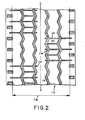
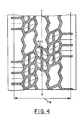
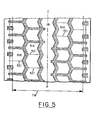
- FIGS 2-5 are fragmentary plan views of modified embodiments of tread designs made in accordance with the present invention.
- a truck tire shall be considered a tire having a nominal rim diameter of at least 15 inches and preferably of at least 18 inches.
- a radial type construction is a tire wherein the cords of the reinforcing structure which extend from bead to bead are disposed at an angle in the range of 75° to 90° with respect to the mid-circumferential centerplane of the tire.
- the tread 10 is provided with four circumferentially extending rows of relief elements, two shoulder rows 15 and two intermediate rows 13.
- Each shoulder or intermediate row comprising circumferentially alternating block portions 14 as shown by dash lines and rib portions 16. Rib portions 16 and block portions . 14 being separated by a groove 21 which remains open when in the footprint of the tire.
- the central portion of the tread 10 is provided with a rib 18 which extends about the circumference of the tire. While the particular embodiment illustrated in figure 1 illustrates four rows of relief elements, the present invention only requires at the least two rows. Preferably, at least four rows as illustrated are disposed in the tread 10.
- the rib portions 16 each comprise a single continuous ground-engaging tread element having a circumferential length CRL of between 20% and 200% of the length LF of the footprint of the tire, preferably between 20% and 100%.
- the circumferential length CBL of block portions 14 is also between 20% and 200% of the footprint length LF of the tire; preferably between 20% and 100%.
- the dash line of figure 1 illustrates the overall outline of the footprint of the tire.
- the maximum tread width TW being the maximum axial width of the tread measured perpendicular to the mid-circumferential centerplane CP as taken from the footprint of the tire inflated to recommended pressure and at rated load.
- the length CRL of rib portions 16 in each intermediate row 13 is approximately 50% of the footprint length LF and the length CRL of rib portions 16 in each shoulder row 15 is approximately 35% of the footprint length LF.
- the circumferential length CBL of block portions 14 in each intermediate row is approximately 35% of the footprint length LF and the length CBL of blook portion in each shoulder row 15 is approximately 50 % of the footprint length LF.
- the circumferential length LF of the footprint is the maximum length of the footprint of the tire measured parallel to the mid-circumferential centerplane CP of the tire as taken from the footprint of the tire inflated to design inflation pressure and loaded at rated load.
- the block portions 14 each comprise at least two separate circumferentially extending relief elements 20 separated by a groove 22.
- the grooves 22 each have a width so that it will not close up at the tread surface when in the footprint of the tire.
- block portions 14 may comprise any desired member of separate circumferential relief elements 20. For example, as illustrated in figures 2, 3 and 4, there may be provided either two, three or four relief elements 20 in block portions 14 in rows 13 or 15.
- the rows of relief elements are separated by circumferentially extending grooves 23, preferably having a zig-zag configuration as is illustrated in figure 1.
- Grooves 23 each have a width such that when in the footprint of the tire they do not close up at the tread surface.
- the block portions 14, rib portions 16, grooves 22 and grooves 23 each have a configuration such that the net contact area of the footprint of the tread of the tire is substantially constant during rotation of the tire, generally the net contact area should not vary by more than approximately 20% and preferably by no more than 10%.
- the net contact area of the tire is that portion of the tread which comes in contact with the ground-engaging surface as a percentage of the total footprint area.
- the tread portion comprises a sufficient number of rib and block portions such that the net contact area of the tire is comprised of at least 20% of relief elements 20 and generally no greater than about 65%.
- the relief elements 20 have a ground-engaging surface area which comprises between 30% to 50% of the net contact area of the footprint and in the particular embodiment illustrated in figure 1, relief elements 20 comprise approximately 35% of the net contact area.
- a tread pattern is obtained which has good traction characteristics associated with block type patterns yet minimizes uneven wear associated with block type patterns.
- a tread design made in accordance with the present invention has good tracking qualities, that is, the tendency to keep the tire traveling in a substantially straight direction thereby providing stability to the tire and good wear properties.
- the tread of the present invention has the benefit of being capable of being used in all seasons of the year and in all positions on truck vehicles such as tractor trailers used on the highway.
- FIG. 2 illustrates a tread pattern wherein notches ' 24 are provided in circumferentially continuous rib portions 118. Additionally, as noted earlier, block portions 114 may be provided with four relief elements 20 as illustrated in intermediate row 113 having relief elements 120.
- figure 3 there is illustrated a modified form of the present invention wherein the central portion of the tread is provided with a row of alternating block portions and rib portions. Additionally, figure 3 illustrates independent relief elements 320 being provided with narrow grooves or blades 321. For the purposes of this invention, narrow grooves or blades shall be considered grooves which close up at the ground-engaging surface when in the footprint of the tire.
- Figure 4 illustrates a modified design wherein the relief elements 420 are also divided circumferentially.
- Figure 5 illustrates another embodiment wherein narrow blades or grooves 521 are provided in the rib portions 516 and/or circumferentially extending rib 18. These narrow grooves or blades close up at the tread surface when in the footprint of the tire.
Abstract
Description
- The foregoing abstract is not to be taken as limiting the invention of this application, and in order to understand the full nature and extent of the technical disclosure of this application, reference must be made to the accompanying drawings and the following detailed description.
- This invention relates to pneumatic tires and more particularly to a pneumatic radial truck tire.
- It is well known in the tire industry that the choice of particular tread pattern involves trade-offs between specific tire performance characteristics. For example, a block type tread design generally provides good mud and snow or off the road traction; however, block type designs are prone to uneven wear, particularly when mounted on the free rolling axles such as the front and trail positions of a tractor trailer unit. On the other hand, a rib type tire, that is, a tire having a plurality of substantially continuous circumferential ribs about the tread generally provides good wear characteristics and tracking qualities which are generally obtained at the expense of traction.
- Applicants have discovered a particular tread configuration which has the good wear and tracking qualities of a rib type tire and the good traction qualities generally attributed to block type patterns.
- Figure 1 is a fragmentary plan view of the tread portion of a pneumatic tire made in accordance with the present invention; and
- Figures 2-5 are fragmentary plan views of modified embodiments of tread designs made in accordance with the present invention.
- Referring to figure 1, there is illustrated a portion of a
tread 10 for a pneumatic truck tire, preferably of the radial type oonstruction. For the purposes of this invention, a truck tire shall be considered a tire having a nominal rim diameter of at least 15 inches and preferably of at least 18 inches. Also for the purposes of this invention, a radial type construction is a tire wherein the cords of the reinforcing structure which extend from bead to bead are disposed at an angle in the range of 75° to 90° with respect to the mid-circumferential centerplane of the tire. Thetread 10 is provided with four circumferentially extending rows of relief elements, twoshoulder rows 15 and twointermediate rows 13. Each shoulder or intermediate row comprising circumferentially alternatingblock portions 14 as shown by dash lines andrib portions 16. Ribportions 16 and block portions . 14 being separated by agroove 21 which remains open when in the footprint of the tire. The central portion of thetread 10 is provided with arib 18 which extends about the circumference of the tire. While the particular embodiment illustrated in figure 1 illustrates four rows of relief elements, the present invention only requires at the least two rows. Preferably, at least four rows as illustrated are disposed in thetread 10. - The
rib portions 16 each comprise a single continuous ground-engaging tread element having a circumferential length CRL of between 20% and 200% of the length LF of the footprint of the tire, preferably between 20% and 100%. The circumferential length CBL ofblock portions 14 is also between 20% and 200% of the footprint length LF of the tire; preferably between 20% and 100%. The dash line of figure 1 illustrates the overall outline of the footprint of the tire. The maximum tread width TW being the maximum axial width of the tread measured perpendicular to the mid-circumferential centerplane CP as taken from the footprint of the tire inflated to recommended pressure and at rated load. In the particular embodiment illustrated, the length CRL ofrib portions 16 in eachintermediate row 13 is approximately 50% of the footprint length LF and the length CRL ofrib portions 16 in eachshoulder row 15 is approximately 35% of the footprint length LF. The circumferential length CBL ofblock portions 14 in each intermediate row is approximately 35% of the footprint length LF and the length CBL of blook portion in eachshoulder row 15 is approximately 50 % of the footprint length LF. For the purposes of this invention, the circumferential length LF of the footprint is the maximum length of the footprint of the tire measured parallel to the mid-circumferential centerplane CP of the tire as taken from the footprint of the tire inflated to design inflation pressure and loaded at rated load. - The
block portions 14 each comprise at least two separate circumferentially extendingrelief elements 20 separated by agroove 22. Thegrooves 22 each have a width so that it will not close up at the tread surface when in the footprint of the tire. Depending upon the circumferential length ofblock portions 14,block portions 14 may comprise any desired member of separatecircumferential relief elements 20. For example, as illustrated in figures 2, 3 and 4, there may be provided either two, three or fourrelief elements 20 inblock portions 14 inrows - In the embodiment illustrated in figure 1, the rows of relief elements are separated by circumferentially extending
grooves 23, preferably having a zig-zag configuration as is illustrated in figure 1.Grooves 23 each have a width such that when in the footprint of the tire they do not close up at the tread surface. - The
block portions 14,rib portions 16,grooves 22 andgrooves 23 each have a configuration such that the net contact area of the footprint of the tread of the tire is substantially constant during rotation of the tire, generally the net contact area should not vary by more than approximately 20% and preferably by no more than 10%. For the purposes of this invention, the net contact area of the tire is that portion of the tread which comes in contact with the ground-engaging surface as a percentage of the total footprint area. The tread portion comprises a sufficient number of rib and block portions such that the net contact area of the tire is comprised of at least 20% ofrelief elements 20 and generally no greater than about 65%. Preferably, therelief elements 20 have a ground-engaging surface area which comprises between 30% to 50% of the net contact area of the footprint and in the particular embodiment illustrated in figure 1,relief elements 20 comprise approximately 35% of the net contact area. - By providing rows of alternating block portions and rib portions in the manner taught by applicants, a tread pattern is obtained which has good traction characteristics associated with block type patterns yet minimizes uneven wear associated with block type patterns. Additionally, a tread design made in accordance with the present invention has good tracking qualities, that is, the tendency to keep the tire traveling in a substantially straight direction thereby providing stability to the tire and good wear properties. Additionally, the tread of the present invention has the benefit of being capable of being used in all seasons of the year and in all positions on truck vehicles such as tractor trailers used on the highway.
- As previously noted, figures 2, 3, 4 and 5 illustrate various forms of the present invention. Figure 2 illustrates a tread pattern wherein
notches ' 24 are provided in circumferentially continuousrib portions 118. Additionally, as noted earlier,block portions 114 may be provided with fourrelief elements 20 as illustrated inintermediate row 113 having relief elements 120. - In figure 3, there is illustrated a modified form of the present invention wherein the central portion of the tread is provided with a row of alternating block portions and rib portions. Additionally, figure 3 illustrates
independent relief elements 320 being provided with narrow grooves orblades 321. For the purposes of this invention, narrow grooves or blades shall be considered grooves which close up at the ground-engaging surface when in the footprint of the tire. - Figure 4 illustrates a modified design wherein the
relief elements 420 are also divided circumferentially. - Figure 5 illustrates another embodiment wherein narrow blades or
grooves 521 are provided in therib portions 516 and/or circumferentially extendingrib 18. These narrow grooves or blades close up at the tread surface when in the footprint of the tire. - While certain representative embodiments and details have been shown for the purposes of illustrating the invention, it will be apparent to those skilled in the art that various changes and modifications may be made therein without departing from the spirit or scope of the present invention.
Claims (8)
Applications Claiming Priority (2)
| Application Number | Priority Date | Filing Date | Title |
|---|---|---|---|
| US06/371,104 US4462445A (en) | 1982-04-23 | 1982-04-23 | Pneumatic tire tread |
| US371104 | 1982-04-23 |
Publications (3)
| Publication Number | Publication Date |
|---|---|
| EP0093072A2 true EP0093072A2 (en) | 1983-11-02 |
| EP0093072A3 EP0093072A3 (en) | 1984-12-05 |
| EP0093072B1 EP0093072B1 (en) | 1987-12-09 |
Family
ID=23462494
Family Applications (1)
| Application Number | Title | Priority Date | Filing Date |
|---|---|---|---|
| EP83630068A Expired EP0093072B1 (en) | 1982-04-23 | 1983-04-21 | A pneumatic tire |
Country Status (5)
| Country | Link |
|---|---|
| US (1) | US4462445A (en) |
| EP (1) | EP0093072B1 (en) |
| JP (1) | JPS58188702A (en) |
| CA (1) | CA1198044A (en) |
| DE (1) | DE3374851D1 (en) |
Cited By (1)
| Publication number | Priority date | Publication date | Assignee | Title |
|---|---|---|---|---|
| EP0402021A2 (en) * | 1989-06-06 | 1990-12-12 | Sumitomo Rubber Industries Limited | Low noise tyre |
Families Citing this family (9)
| Publication number | Priority date | Publication date | Assignee | Title |
|---|---|---|---|---|
| IT8722144V0 (en) * | 1986-08-05 | 1987-07-31 | Uniroyal Englebert Gmbh | CARVING OF TIRES OF MOTOR VEHICLES. |
| JPS63287605A (en) * | 1987-05-20 | 1988-11-24 | Bridgestone Corp | Pneumatic tire |
| USD387715S (en) * | 1996-12-09 | 1997-12-16 | The Goodyear Tire & Rubber Company | Tire tread |
| USD410420S (en) * | 1998-06-11 | 1999-06-01 | The Goodyear Tire & Rubber Company | Tire tread |
| USD421944S (en) * | 1999-05-28 | 2000-03-28 | The Goodyear Tire & Rubber Company | Tire tread |
| US20050173035A1 (en) * | 2004-02-10 | 2005-08-11 | Richard Heinen | Elongated block tire tread |
| US7926533B2 (en) | 2007-10-31 | 2011-04-19 | The Goodyear Tire & Rubber Company, Inc. | Pneumatic tire with increased lower sidewall durability |
| US8056592B2 (en) * | 2007-10-31 | 2011-11-15 | The Goodyear Tire + Rubber Company, Inc. | Grip tire with added puncture protection |
| JP6790495B2 (en) * | 2016-06-24 | 2020-11-25 | 住友ゴム工業株式会社 | tire |
Citations (5)
| Publication number | Priority date | Publication date | Assignee | Title |
|---|---|---|---|---|
| US3001568A (en) * | 1958-01-30 | 1961-09-26 | Suominen Lauri Leevi Ensio | Tire for vehicle wheels |
| US3004578A (en) * | 1960-06-03 | 1961-10-17 | Continental Gummi Werke Ag | Tire treads |
| NL262155A (en) * | 1944-07-19 | 1964-05-25 | ||
| FR2205423A1 (en) * | 1972-11-02 | 1974-05-31 | Uniroyal Ag | |
| US4278121A (en) * | 1979-11-23 | 1981-07-14 | The Firestone Tire & Rubber Company | All-season pneumatic tire tread |
Family Cites Families (7)
| Publication number | Priority date | Publication date | Assignee | Title |
|---|---|---|---|---|
| US1956011A (en) * | 1932-02-18 | 1934-04-24 | Wingfoot Corp | Means for diminishing traction and riding noise in tires |
| GB581086A (en) * | 1944-05-31 | 1946-10-01 | Henley S Tyre & Rubber Company | Improvements in tyres for vehicles |
| JPS5130466B2 (en) * | 1973-06-22 | 1976-09-01 | ||
| JPS547082B2 (en) * | 1973-11-22 | 1979-04-04 | ||
| CH618127A5 (en) * | 1977-04-18 | 1980-07-15 | Semperit Ag | Pneumatic tyre for vehicles |
| US4327792A (en) * | 1978-02-14 | 1982-05-04 | The Goodyear Tire & Rubber Company | Spreading noise generated by load supporting elements |
| JPS5510403A (en) * | 1978-07-04 | 1980-01-24 | Asahi Dow Ltd | Prefoamed article |
-
1982
- 1982-04-23 US US06/371,104 patent/US4462445A/en not_active Expired - Fee Related
-
1983
- 1983-04-12 JP JP58063125A patent/JPS58188702A/en active Pending
- 1983-04-15 CA CA000425944A patent/CA1198044A/en not_active Expired
- 1983-04-21 EP EP83630068A patent/EP0093072B1/en not_active Expired
- 1983-04-21 DE DE8383630068T patent/DE3374851D1/en not_active Expired
Patent Citations (5)
| Publication number | Priority date | Publication date | Assignee | Title |
|---|---|---|---|---|
| NL262155A (en) * | 1944-07-19 | 1964-05-25 | ||
| US3001568A (en) * | 1958-01-30 | 1961-09-26 | Suominen Lauri Leevi Ensio | Tire for vehicle wheels |
| US3004578A (en) * | 1960-06-03 | 1961-10-17 | Continental Gummi Werke Ag | Tire treads |
| FR2205423A1 (en) * | 1972-11-02 | 1974-05-31 | Uniroyal Ag | |
| US4278121A (en) * | 1979-11-23 | 1981-07-14 | The Firestone Tire & Rubber Company | All-season pneumatic tire tread |
Cited By (2)
| Publication number | Priority date | Publication date | Assignee | Title |
|---|---|---|---|---|
| EP0402021A2 (en) * | 1989-06-06 | 1990-12-12 | Sumitomo Rubber Industries Limited | Low noise tyre |
| EP0402021A3 (en) * | 1989-06-06 | 1991-05-29 | Sumitomo Rubber Industries Limited | Low noise tyre |
Also Published As
| Publication number | Publication date |
|---|---|
| EP0093072A3 (en) | 1984-12-05 |
| US4462445A (en) | 1984-07-31 |
| EP0093072B1 (en) | 1987-12-09 |
| DE3374851D1 (en) | 1988-01-21 |
| JPS58188702A (en) | 1983-11-04 |
| CA1198044A (en) | 1985-12-17 |
Similar Documents
| Publication | Publication Date | Title |
|---|---|---|
| US4462446A (en) | Pneumatic tire tread | |
| AU601089B2 (en) | Pneumatic tire | |
| US4700762A (en) | Pneumatic tire therad with wide central groove and arcuate grooves | |
| US6481480B1 (en) | Convertible tread for a radial truck or trailer tire | |
| KR100285092B1 (en) | Automotive Air Tires | |
| EP0428472B1 (en) | Asymmetric tire | |
| CA2039199C (en) | Winter type tire tread | |
| EP0139606B1 (en) | A pneumatic tire | |
| US4574856A (en) | Tread for a pneumatic tire | |
| JP2512046Y2 (en) | Agricultural pneumatic tires | |
| EP3715147B1 (en) | Low noise tire tread | |
| CA2018817C (en) | Tractor tire | |
| EP0295195B1 (en) | A pneumatic tire | |
| CA2028892C (en) | Tire tread | |
| EP0912355B1 (en) | A convertible tread for a radial truck or trailer tire | |
| EP3552844B1 (en) | Tyre | |
| US4779656A (en) | Pneumatic tire | |
| US4856571A (en) | Pneumatic tire | |
| US4462445A (en) | Pneumatic tire tread | |
| US8261790B2 (en) | Directional tread for a tire | |
| US4739812A (en) | Pneumatic tire tread with recessed shoulder portion | |
| US4574857A (en) | Tractor tire tread | |
| JPH04266505A (en) | Tire tread for winter months | |
| CA1143265A (en) | Tire tread with independent projections | |
| CA2080328C (en) | Pneumatic tire |
Legal Events
| Date | Code | Title | Description |
|---|---|---|---|
| PUAI | Public reference made under article 153(3) epc to a published international application that has entered the european phase |
Free format text: ORIGINAL CODE: 0009012 |
|
| 17P | Request for examination filed |
Effective date: 19830505 |
|
| AK | Designated contracting states |
Designated state(s): DE FR GB IT LU |
|
| PUAL | Search report despatched |
Free format text: ORIGINAL CODE: 0009013 |
|
| AK | Designated contracting states |
Designated state(s): DE FR GB IT LU |
|
| 17Q | First examination report despatched |
Effective date: 19860527 |
|
| GRAA | (expected) grant |
Free format text: ORIGINAL CODE: 0009210 |
|
| AK | Designated contracting states |
Kind code of ref document: B1 Designated state(s): DE FR GB IT LU |
|
| REF | Corresponds to: |
Ref document number: 3374851 Country of ref document: DE Date of ref document: 19880121 |
|
| ET | Fr: translation filed | ||
| ITF | It: translation for a ep patent filed |
Owner name: MODIANO & ASSOCIATI S.R.L. |
|
| PLBE | No opposition filed within time limit |
Free format text: ORIGINAL CODE: 0009261 |
|
| STAA | Information on the status of an ep patent application or granted ep patent |
Free format text: STATUS: NO OPPOSITION FILED WITHIN TIME LIMIT |
|
| 26N | No opposition filed | ||
| REG | Reference to a national code |
Ref country code: FR Ref legal event code: CL |
|
| PGFP | Annual fee paid to national office [announced via postgrant information from national office to epo] |
Ref country code: GB Payment date: 19930319 Year of fee payment: 11 |
|
| PGFP | Annual fee paid to national office [announced via postgrant information from national office to epo] |
Ref country code: LU Payment date: 19930402 Year of fee payment: 11 |
|
| PGFP | Annual fee paid to national office [announced via postgrant information from national office to epo] |
Ref country code: FR Payment date: 19930412 Year of fee payment: 11 |
|
| PGFP | Annual fee paid to national office [announced via postgrant information from national office to epo] |
Ref country code: DE Payment date: 19930428 Year of fee payment: 11 |
|
| ITTA | It: last paid annual fee | ||
| EPTA | Lu: last paid annual fee | ||
| PG25 | Lapsed in a contracting state [announced via postgrant information from national office to epo] |
Ref country code: LU Free format text: LAPSE BECAUSE OF NON-PAYMENT OF DUE FEES Effective date: 19940421 Ref country code: GB Effective date: 19940421 |
|
| GBPC | Gb: european patent ceased through non-payment of renewal fee |
Effective date: 19940421 |
|
| PG25 | Lapsed in a contracting state [announced via postgrant information from national office to epo] |
Ref country code: FR Effective date: 19941229 |
|
| PG25 | Lapsed in a contracting state [announced via postgrant information from national office to epo] |
Ref country code: DE Effective date: 19950103 |
|
| REG | Reference to a national code |
Ref country code: FR Ref legal event code: ST |