EP0092367A2 - Sensor using fiber interferometer - Google Patents
Sensor using fiber interferometer Download PDFInfo
- Publication number
- EP0092367A2 EP0092367A2 EP83302058A EP83302058A EP0092367A2 EP 0092367 A2 EP0092367 A2 EP 0092367A2 EP 83302058 A EP83302058 A EP 83302058A EP 83302058 A EP83302058 A EP 83302058A EP 0092367 A2 EP0092367 A2 EP 0092367A2
- Authority
- EP
- European Patent Office
- Prior art keywords
- coil
- light
- signal
- light signals
- counterpropagating
- Prior art date
- Legal status (The legal status is an assumption and is not a legal conclusion. Google has not performed a legal analysis and makes no representation as to the accuracy of the status listed.)
- Granted
Links
- 239000000835 fiber Substances 0.000 title claims description 79
- 230000003287 optical effect Effects 0.000 claims abstract description 34
- 230000010363 phase shift Effects 0.000 claims abstract description 33
- 239000013307 optical fiber Substances 0.000 claims abstract description 10
- 230000010287 polarization Effects 0.000 claims description 54
- 230000000694 effects Effects 0.000 claims description 39
- 230000008859 change Effects 0.000 claims description 30
- 230000001902 propagating effect Effects 0.000 claims description 15
- 238000002839 fiber optic waveguide Methods 0.000 claims description 13
- 238000000034 method Methods 0.000 claims description 13
- 230000004044 response Effects 0.000 claims description 8
- 230000005540 biological transmission Effects 0.000 claims description 5
- 230000008878 coupling Effects 0.000 claims description 4
- 238000010168 coupling process Methods 0.000 claims description 4
- 238000005859 coupling reaction Methods 0.000 claims description 4
- 230000004323 axial length Effects 0.000 claims description 2
- 230000007613 environmental effect Effects 0.000 description 12
- 230000035945 sensitivity Effects 0.000 description 5
- 230000001427 coherent effect Effects 0.000 description 4
- 230000009699 differential effect Effects 0.000 description 4
- 230000006835 compression Effects 0.000 description 3
- 238000007906 compression Methods 0.000 description 3
- 230000003993 interaction Effects 0.000 description 3
- 230000001186 cumulative effect Effects 0.000 description 2
- 238000010586 diagram Methods 0.000 description 2
- 238000006073 displacement reaction Methods 0.000 description 2
- 239000000463 material Substances 0.000 description 2
- 230000004048 modification Effects 0.000 description 2
- 238000012986 modification Methods 0.000 description 2
- 238000000926 separation method Methods 0.000 description 2
- 238000004804 winding Methods 0.000 description 2
- 230000009471 action Effects 0.000 description 1
- 239000000654 additive Substances 0.000 description 1
- 230000000996 additive effect Effects 0.000 description 1
- 238000005452 bending Methods 0.000 description 1
- 230000008901 benefit Effects 0.000 description 1
- 230000002457 bidirectional effect Effects 0.000 description 1
- 230000009194 climbing Effects 0.000 description 1
- 230000001934 delay Effects 0.000 description 1
- 230000001419 dependent effect Effects 0.000 description 1
- 238000005562 fading Methods 0.000 description 1
- 238000001914 filtration Methods 0.000 description 1
- 230000007774 longterm Effects 0.000 description 1
- 238000004519 manufacturing process Methods 0.000 description 1
- 230000003014 reinforcing effect Effects 0.000 description 1
Images

Classifications
-
- G—PHYSICS
- G01—MEASURING; TESTING
- G01R—MEASURING ELECTRIC VARIABLES; MEASURING MAGNETIC VARIABLES
- G01R29/00—Arrangements for measuring or indicating electric quantities not covered by groups G01R19/00 - G01R27/00
-
- G—PHYSICS
- G01—MEASURING; TESTING
- G01D—MEASURING NOT SPECIALLY ADAPTED FOR A SPECIFIC VARIABLE; ARRANGEMENTS FOR MEASURING TWO OR MORE VARIABLES NOT COVERED IN A SINGLE OTHER SUBCLASS; TARIFF METERING APPARATUS; MEASURING OR TESTING NOT OTHERWISE PROVIDED FOR
- G01D5/00—Mechanical means for transferring the output of a sensing member; Means for converting the output of a sensing member to another variable where the form or nature of the sensing member does not constrain the means for converting; Transducers not specially adapted for a specific variable
- G01D5/26—Mechanical means for transferring the output of a sensing member; Means for converting the output of a sensing member to another variable where the form or nature of the sensing member does not constrain the means for converting; Transducers not specially adapted for a specific variable characterised by optical transfer means, i.e. using infrared, visible, or ultraviolet light
- G01D5/32—Mechanical means for transferring the output of a sensing member; Means for converting the output of a sensing member to another variable where the form or nature of the sensing member does not constrain the means for converting; Transducers not specially adapted for a specific variable characterised by optical transfer means, i.e. using infrared, visible, or ultraviolet light with attenuation or whole or partial obturation of beams of light
- G01D5/34—Mechanical means for transferring the output of a sensing member; Means for converting the output of a sensing member to another variable where the form or nature of the sensing member does not constrain the means for converting; Transducers not specially adapted for a specific variable characterised by optical transfer means, i.e. using infrared, visible, or ultraviolet light with attenuation or whole or partial obturation of beams of light the beams of light being detected by photocells
- G01D5/353—Mechanical means for transferring the output of a sensing member; Means for converting the output of a sensing member to another variable where the form or nature of the sensing member does not constrain the means for converting; Transducers not specially adapted for a specific variable characterised by optical transfer means, i.e. using infrared, visible, or ultraviolet light with attenuation or whole or partial obturation of beams of light the beams of light being detected by photocells influencing the transmission properties of an optical fibre
- G01D5/35303—Mechanical means for transferring the output of a sensing member; Means for converting the output of a sensing member to another variable where the form or nature of the sensing member does not constrain the means for converting; Transducers not specially adapted for a specific variable characterised by optical transfer means, i.e. using infrared, visible, or ultraviolet light with attenuation or whole or partial obturation of beams of light the beams of light being detected by photocells influencing the transmission properties of an optical fibre using a reference fibre, e.g. interferometric devices
-
- G—PHYSICS
- G01—MEASURING; TESTING
- G01H—MEASUREMENT OF MECHANICAL VIBRATIONS OR ULTRASONIC, SONIC OR INFRASONIC WAVES
- G01H9/00—Measuring mechanical vibrations or ultrasonic, sonic or infrasonic waves by using radiation-sensitive means, e.g. optical means
- G01H9/004—Measuring mechanical vibrations or ultrasonic, sonic or infrasonic waves by using radiation-sensitive means, e.g. optical means using fibre optic sensors
-
- G—PHYSICS
- G01—MEASURING; TESTING
- G01J—MEASUREMENT OF INTENSITY, VELOCITY, SPECTRAL CONTENT, POLARISATION, PHASE OR PULSE CHARACTERISTICS OF INFRARED, VISIBLE OR ULTRAVIOLET LIGHT; COLORIMETRY; RADIATION PYROMETRY
- G01J9/00—Measuring optical phase difference; Determining degree of coherence; Measuring optical wavelength
- G01J9/02—Measuring optical phase difference; Determining degree of coherence; Measuring optical wavelength by interferometric methods
- G01J2009/0226—Fibres
Definitions
- This invention relates generally to closed loop or "Sagnac" fiber optic interferometers, and, more particularly, the invention relates to sensors for environmental quantities which can affect fiber optic waveguides in fiber optic interferometers.
- Interferometers work on the principal of phase change between two coherent signals which are interfered together. Closed loop interferometers measure the relative phase change on a "global" scale, i.e., they measure the overall relative phase change between two counterpropagating light signals in a single loop of fiber.
- the optical fiber loops of interferometers are sensitive to a large number of environmental effects such as temperature, acoustic pressure, vibration, motion, and electric and magnetic fields. These external phenomena can change the optical transmission characteristics of the fiber such as by changing the birefringence in the fiber or the geometric path length or the velocity of propagation of light signals through the fiber, which can result in changes in the amplitude, phase, or polarization of light propagating therethrough.
- This sensitivity to environmental effects means that fiber interferometer loops may function as sensor elements so long as the desired quantity to be sensed can be isolated from the other environmental quantities to which the fiber is sensitive.
- the closed loop interferometer is typically used to sense non-reciprocal differential effects, such as rotation.
- a polarizer which limits the optical paths of the couterpropagating light to a single one of the polarization modes, as disclosed in copending U.S. patent application Serial No. 319,311, filed November 9, 1981 which is a continuation in part of U.S. patent application serial number 307, 095 filed on September 30, 1981 which is a continuation in part of U.S. patent application serial number 249,714 filed on March 31, 1981
- the closed loop interferometer is basically stable and, on a global scale, is relatively insensitive to environmental effects other than non- reciprocal, differential effects, such as motion.
- any reciprocal, differential environmental phenomena such as temperature or pressure, affects the fiber optical light transmission characteristics of both counterpropagating light signals substantially equally and, therefore, results in little or no relative phase change between the counterpropagating signals.
- the present invention teaches a closed loop interferometer configuration which senses differential reciprocal effects, such as accoustic pressure, by making their effect on the global scale non-reciprocal.
- the present invention is directed to use of the closed loop optical interferometer to sense environmental phenomena which normally produce reciprocal effects on an infinitesimal length of fiber by causing them to produce non-reciprocal effects. Briefly, this is accomplished by making the sensed phenomenon spatially asymetrical and non-uniform with respect to the closed loop.
- the fundamental principal which is utilized in the three basic embodiments disclosed herein is to cause the quantity Q to be sensed to be applied to the closed loop of the interferometer such that Q is time varying and is applied at a point that offset from the center of the path around the loop i.e., a rapidly time varying Q is applied at a point on the path such that one of the counterpropagating light signals has farther to travel to the detector than the other.
- counterpropagating waves or the term “counterpropagating light signals” means collectively both of the light signals travelling in opposite directions in the loop of the interferometer.
- counterpropagating wave or light signal means only the light wave travelling in the loop in the direction opposite the direction of travel for the acoustic wave.
- two counterpropagating light signals is disclosed in the first two embodiments disclosed because it is easier to grasp the basic principle by these two examples.
- These two embodiments are sensors for acoustic waves which utilize coils of fiber optic waveguide that are specially wound so that the effect of the acoustic wave is non-uniform on the two counterpropagating light waves.
- the loop is wound and arranged with respect to the wave to be sensed such that the subject wave has a uniform effect on the co-propagating light signal, i.e., the light signal traveling in the same direction as the subject wave, but has a non-uniform effect on the counterpropagating light signal.
- This is done in the first embodiment by winding the coil such that the axial velocity of the co-propagating light wave along the longitudinal axis of the coil matches the velocity of propagation of the acoustic wave along the longitudinal axis.
- the fundemental principle is utilized by winding two coils separated in space by 1/4 of the wavelength of the- acoustic wave with the size of the coil diameter and the number of turns selected such that the transit time for the light signals through each coil is 1/4 of the period of the acoustic wave.
- the length of each coil is also selected such that the coil occupies a very small space compared to the wavelength of the acoustic wave such that the coil is affected substantially ,uniformly by the portion of the acoustic wave by which it is enveloped.
- the quantity Q to be sensed is applied to the loop of the interferometer such that it is time varying and spatially asymmetrical. Because the quantity Q is applied asymmetrically to the loop, variations in Q will affect each of the counterpropagating wave differently thereby producing a phase difference therebetween. However, if Q is a slowly varying quantity such as temperature, the value of Q may not.change appreciably between the arrival times of the two counterpropagating waves at the point on the loop where Q is applied, so that each wave is affected substantially the same by Q.
- the quantity Q is modulated onto a bias or carrier frequency which is rapidly time varying by a convential modulator and applied to the loop at a point which is offset from the geometric of the path between the light source and the detector.
- the modulated Q i.e., q(t)
- the loop is applied to the loop with a phase modulator which stretches the fiber in proportion to the amplitude of q(t).
- the invention utilizes the inherent stability and quieter operations of the closed loop interferometer to sense reciprocal quantities by causing them to produce nonreciprocal effects.
- the result is a quieter, more sensitive sensor which is better able to distinguish the effects of the desired quantity to be sensed from the effects of undesired quantities.
- the delay line function of the closed loop increases the sensitivity to the quantity Q and allows a lower modulation frequency for the quantity Q when the invention is being used to sense slowly varying quantities such as temperature.
- an object of the invention is a sensor which utilizes a closed loop fiber optic interferometer.
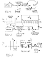
- Figure 1 is a simplified schematic of a closed loop fiber optic interferometer such as is used in the rotation sensor disclosed in copending U.S. patent application serial number 319,311, filed November 9,1981 which is a continuation in part of U.S. patent application serial number 307,095 filed on September 30, 1981 which is a continuation in part of U.S. patent application serial number 249,714 filed on March 31, 1981 the details of all of said patent applications being hereby incorporated by reference.
- a light source 10 generates a beam of light which is transmitted through an optical fiber 12 and polarizer 13 to a fiber optic directional coupler 14.
- a directional coupler could also be used to perform the beam splitting function.
- the light beam is split into two waves which propagate through the closed loop 16 in opposite directions as indicated by ,the arrows. After propagating through the loop 16 the two beams are recombined and pass through the optical fiber 12 to the polarizer 13 and then to a second fiber optic directional coupler 18 which directs the combined signals to a detector 20.
- the detector responds to the intensity of the combined waves which depends on the differences in phase between the two counterpropagating waves and provides an output signal indicative of the phase shift. Since the rotation of the fiber coil has a nonreciprocal effect on the counterpropagating waves, the detector gives a measure of the rotation.
- the closed loop interometer may also employ directional couplers, polarization controllers, phase modulators, and lock-in amplifiers as described in the co-pending application and as described by Bergh, Lefevre and Shaw in "All-single-mode fiber-optic Gyroscope with Long Term Stability", Optics Letters, Vol 6, No. 10, Oct. 1981 and in “All-Single mode Fiber-Optic Gyroscope", Optics Letters, Vol. 6, No. 4, April 1981.
- the interferometer can take the form of an all fiber integrated device in which all components are constructed in a single monomode fiber.
- the phase modulators if used, can provide bias which increases sensitivity and linearity of response.
- Examples of normally differentially reciprocal effects which do not strongly affect the interferometer of Figure 1 are temperature, force, stress, pressure, displacement, strain, vibration and acoustic waves.
- FIG 2 is a schematic of an acoustic wave sensor employing a closed loop interferometer in accordance with one embodiment of the invention.
- the acoustic wave sensor is similar in configuration to the rotation sensor of Figure 1.
- the coil 24 is wound in an extended helical pattern having a longitudional axis "x" lying along the direction of travel of an acoustic wave 26 to be sensed.
- the sensor comprises a closed loop fiber optic waveguide 24 which is coiled into a number of turns.
- the diameter, D, of the turns, the number of the turns, N, and the spacing of the turns along the longitudinal axis x are selected to meet certain criteria. That criteria is that the acoustic wave 26 to be sensed must travel down the longitudional axis x of the coil at the same velocity as that of a co-propagating optical signal traveling in the coil 24 from the A end to the B end would have. That is, as the light wave travels around the turns in the coil, it works its way toward the B end at a certain axial rate as if the light wave were climbing up the threads of a very finely threaded screw.
- This axial velocity for the light wave is much slower than the actual velocity of propagation in the fiber because there are many turns and each is approximately parallel to the planes 28 of the acoustic wave.
- Acoustic waves have planes of acoustic compression and rarifaction which are orthogonal to the direction of propagation of the acoustic wave.
- the planes 28, for a sound wave represent peaks of higher pressure medium in the acoustic wave .and the spaces 30 represent areas of lower pressure medium.
- the coil is configured to maximize the overall global, non-reciprocal effect of the acoustic wave on the coil.
- the coil is configured with respect to the acoustic wave such that the effect of the acoustic wave on the coil is time varying and spatially non-uniform so as to cause a relative phase shift between the counterpropagating waves.
- the diameters of the coil and the number of turns are selected such that an optical wave travels the length of the coil 24 in a time T 1 which is equal to the time, T a , for an acoustic wave to travel the axial length of helical coil 24. Accordingly, a wave propagating through the coil from left to right experiences a constant pressure from the acoustic wave, whereas an optical wave travelling from right to left experiences a continually varying effect.
- the number and diameter of spacing of the turns in the coil 24 are selected such that as a light wave enters the A end of the fiber, its speed of travel down the x axis toward the B end matches the speed of propagation of the acoustic wave 26 along the x axis toward the B end.
- the pulse or burst of light will continually travel in fiber which is subjected to the same pressure from the same part of the acoustic wave 28.
- This pressure changes the geometric path length that the co-propagating wave travels from A to B because each segment of fiber that the light wave travels in is equally stretched or compressed by the pressure effects from the traveling acoustic wave.
- the situation is not the same for the counterpropagating wave however.
- the counterpropagating light wave traveling from the B end to the A end first encounters segments of fiber that are compressed by the peaks 28 of the acoustic wave and then encounters fiber segments that are stretched by the troughs 30.
- the geometric path that the counterpropagating light wave travels is thus alternately made longer then shorter by the acoustic wave.
- the net path length change for the counterpropagating wave will be zero.
- the result is a net phase shift between the two counterpropagating light waves which is linearly proportional to the amplitude of the acoustic wave 26 and to the length, L, of the coil 24. That is, for longer coil lengths, L, the acoustic wave has a greater interaction distance with the fiber in which the co-propagating light wave is traveling. The total increase in path length, and the resulting phase shift, therefore increases with greater interaction length, L.
- the greatest directivity or discrimination of the coil 24 results when the coil length, L, is chosen to be some integer multiple of the acoustic wavelength because the net phase shift is then zero for the counterpropagating wave, i.e., the wave which is travelling in the fiber in an axial direction opposite the direction of propagation of the acoustic wave, resulting in the best performance of the sensor.
- L can be any non-neglible fraction of the wavelength of the acoustic wave which is sufficient to create a discernible relative phase shift betwen the counterpropagating waves which is indicative of the amplitude of the acoustic wave.
- the frequency for an acoustic wave of unknown frequency propagating with a known velocity could be determined by using a variable length delay line and tuning the line for zero phase shift in the counterpropagating wave.
- the counterpropagating light waves in the loop 24 are produced by a light source 32 coupling light waves into a fiber 34 which guides the waves through a polarizer 36 to a fiber optic directional coupler 38 coupled to the two ends of the coil 24.
- the light source 32 can have a coherence length which is very short. That is, as long as the coherence length of the source exceeds the differential path length through the coil caused by the acoustic wave, the two counterpropagating waves will still be coherent after traveling the length of the coil, and they can be successfully merged to interfere with each other. The interference is necessary to be able to determine the amount of the relative phase shift.
- the fiber 34 is, in the preferred embodiment, a monomode fiber.
- the polarizer 36 is bidirectional, and can be adjusted to pass only light of a predetermined polarization.
- the polarizer 36 is important in maintaining the reciprocal operational characteric of the closed,loop interferometer as is known in the art.
- the polarizer insures that the light going into the loop is in only one polarization. Any birefringence in the fiber of the loop will couple part of the energy to the orthogonal polarization mode where the propagation velocity is different from the velocity in the selected polarization. If the birefringence is not symmetric about the center of the geometric path, the counterpropagating waves will travel differing distances at the new velocities and will suffer different phase shifts.
- the polarizer only allows light of one polarization to enter the fiber and blocks all returning light energy in polarization modes other than the input polarization mode.
- the detector will only see light energy from the components of the counterpropagating waves which travelled through the loop in the selected polarization mode, and there will be no phase shift since both counterpropagating signals will have travelled the same geometric path length in the same polarization mode, i.e., at the same velocity.
- the directional coupler 38 splits the polarized light wave travelling toward the loop from the polarizer 36 into two coherent light waves and couples each wave into one end of the coil 24, so that they counterpropagate.
- a beam splitter could be used in place of the directional coupler 38, but the directional coupler is the preferred embodiment since the fiber is continuous from the source 32 through the coupler and back to the detector.
- a beam splitter joins separate fibers, the ends of which generate reflected waves. These reflected waves bounce back into the input fiber and interfere with the incoming light waves and can cause undesirable standing waves.
- the use of beam splitters is not a problem in terms of reflections where pulsed operation is used. In pulsed operation, the source 32 provides pulses separated by dark periods. By adjusting the length of fiber in the system and the pulse separation and duration, it is possible to cause the reflected signals to arrive at the detector during dark periods between the initial pulse and the returning combined pulse from the counterpropagating pulses.
- the fiber optic directional coupler 38 also recombines the counterpropagating light signals after they have passed through the loop. The combined signal then is coupled into the input fiber 34 and passes through the polarizer 36 on its way to a photodetector 40. Between the polarizer 36 and the source 32, a second fiber optic directional coupler 42 is coupled to the input fiber 34.
- This second coupler 42 diverts part of the energy from the combined signal returning from the loop 24 into the input of the photodetector 40.
- the photodetector then generates a signal proportional to the intensity of the combined signal which can be interpreted to determine the relative phase shift. This is known in the art.
- a polarization controller 44 is placed in the loop 24 to control the polarization of light signals traveling in the loop. This is desirable to prevent "signal fading" caused by the interaction of the polarizer 36 with birefringence zones in the loop 24. For example, if the polarizer only allows vertically polarized light in and out of the loop, and birefringence in the loop couples all the energy from the counterpropagating light signals into the horizontal polarization mode, then the polarizer 36 would block all output light and the detector would register a zero output.
- the structure of polarization controllers is known in the art. These devices are capable of taking input light at one polarization and shifting it to output light at any other selected polarization.
- the polarization controller 44 By properly adjusting the polarization controller 44 it is possible to insure that at least some of the light, and preferably most of the light, exits the loop in the polarization passed by the polarizer,36. That is, the polarization controller can be used to maximize the output signal from the detector. This prevents environmentally caused birefringence and birefringence in the fiber structure caused by residual stress from manufacturing processes from causing signal fadeout.
- the time varying and spatially non-uniform effect of the acoustic wave on counterpropagating optical waves in coil 24 varies the intensity of the recombined optical wave which can then be detected as a measure of the amplitude of the acoustic wave.
- One possible use for the embodiment described in Figures 2 and 3 is as a direction finder for acoustic waves. This can be done by turning the loop longitudinal axis until the output signal is a maximum.
- the sensitivity of the sensor can be increased by increasing L, especially in increments of the wavelength of the acoustic wave 26.
- FIG. 3 is a schematic diagram of an acoustic sensor employing a closed loop interferometer in accordance with another embodiment of the invention.
- the coil 46 is separated into two separate, spaced groups of coils designated Cl and C2, one consisting of the first- contiguous turns and the other consisting of the last contiguous turns of the optical fiber.
- the two groupings of coils are displaced along the x axis with respect to each other by a distance, d, such that the planes of the two groups of coils remain mutually parallel.
- the displacement, d, between the two groups of coils is chosen, in the preferred embodiment, to be an odd multiple of one quarter wavelength of the acoustic wave shown generally at 47.
- the total length of the fiber used to form the two groups of coils is such that the optical transit time through both coils is one-half the period of the acoustic wave frequency.
- the distance d could be some other fraction of the wavelength of the acoustic wave if the sizes of the coils Cl and C2 are adjusted so that the optical transit times are the same fraction of the period of the acoustic wave that the distance d is to the wavelength of the acoustic wave.
- the sensor is not as directionally selective.
- the senor will not discriminate as sharply between acoustic waves whose direction of propagation is parallel to the longitudinal axis x of the coils and acoustic waves whose direction of propagation is not parallel to the longitudinal axis of the coil.
- the result of the foregoing structure is to cause a relative phase shift between counterpropagatng light waves when an acoustic wave of the specified wavelength is propagating down the x axis.
- This phase shift is caused by the acoustic wave pressures acting on the counterpropagating light waves in a non-reciprocal fashion where such a wave would normally cause a reciprocal effect in an interferometer structure like the device of Figure 1.
- the distance d between the two groups of coils is selected to be 1/4 of the acoustic wave wavelength.
- the coils Cl and C2 are sized such that the optical transit time therethrough is equal to 1/4 of the period of the acoustic wave.
- the coils are also sized such that their lengths Ll and L2 are small compared to the wavelength of the acoustic wave.
- the coils have a longitudinal axis x which is arranged to be parallel to the axis of propagation of the acoustic wave for maximum sensitivity.
- the curves 48 and 50 represent" the acoustic wave separated by 1/4th of the wavelength at the two instants in time tl and t2 which instants in time are separated by 1/4 of the period of the acoustic wave. That is, the curve 48 represents the situation at the time tl, i.e., it shows how the coils Cl and C2 are enveloped by the peaks and troughs of acoustic pressure at the time tl where the peaks and troughs of pressure are represented by the areas 52 and 54 respectively. Likewise, the curve 50 shows how the coils Cl and C2 are enveloped by the acoustic wave at the point in time t2 1/4 period later.
- the coil Cl is experiencing a substantially uniform acoustic pressure throughout the coil at the pressure level illustrated at 56.
- the coils Cl and C2 are separated by 1/4 of the acoustic wavelength and the instant of time tl happens to be a time when the wave peak is exactly centered between the coils. At some other later or earlier time, this would not be the case.
- the principal at work in the embodiment of Figure 3 holds true for any time t however.
- the co-propagating light signal in the coil Cl and the counterpropagating light signal in the coil C2 at the time tl thus experience equal changes in their geometric path lengths and, therefore, the transit time for each light signal through the whole loop is changed. Because the coils Cl and C2 are sized such that it takes each of the counterpropagating light signals 1/4 period of the acoustic wave to propagate through each coil, the co-propagating light signal in Cl stays in the coil Cl until the time t2, at which time it exits on the fiber segment 62.
- this co-propagating light signal enters the coil C2 which is immersed in the acoustic wave as shown at 64 on curve 50 in Figure 4(B).
- the counterpropagating wave in the coil C2 at the time tl stays in C2 until the time t2 and then travels through the segment 62 and enters the coil Cl.
- the coils Cl and C2 are immersed in acoustic pressure at the corresponding amplitudes as shown by points 64 and 66, respectively.
- the co-propagating light signal which was in coil group Cl at time tl and experienced the pressure at 56 in Figure 4(A) is now in coil group C2 at time t2 and experiences the same positive compression effects from the acoustic wave 47 as shown at 64 in Figure 4(B).
- These compressive effects change the geometric path length through the coil C2 in the same amount and in the same sign as occurred in the coil C1 at the time tl.
- the transit time through the coil C2 is changed and is of the same sign as the change in transit time experienced in the coil Cl at the time tl.
- the overall change in transit time for the co-propagating signal is additive and non- zero therefore.
- the counterpropagating light signal which was in coil group C2 at tl experiences the pressure at 58 in Figure 4(A) and then travels to the left and is in coil Cl at time t2 where it experiences an equal and opposite pressure illustrated at 66 in Figure 4(B).
- the counterpropagating light signal experiences a path length change in the coil Cl which is equal and opposite to the path length change it experienced in the coil C2.
- the change in transit time caused by the coil C2 is cancelled by the change in transit time.,caused by the coil Cl, and the counterpropagating light signal will have a net change in transit time through the coil 46 of zero.
- the effect on the wave propagating from coil Cl to C2 is reinforcing while the effect on the signal propagating from coil C2 to coil Cl is offsetting. Accordingly, the counterpropagating waves contain a relative phase difference when recombined after propagating through the two groups of coils. This phase difference is then detected and can be interpreted linearly to determine the amplitude of the acoustic wave.
- the sensor will still work to sense the presence of waves but the counterpropagating wave will not have a net zero transit time change.
- the response of the sensor in this case will be non-linear.
- Both the sensors of Figure 2 and 3 have a certain bandwidth in which they are useful.
- the center frequency of each bandwidth is the frequency having the wavelength which causes a net zero phase shift in the counterpropagating light signal. At other wavelengths, the response falls off somewhatbecause of various effects.
- the optical coil interferometer also functions as the sensor for the measured acoustical wave.
- both embodiments require that the coils be designed for a particular frequency of acoustic wave for optimal operation unless a variable coil length can be achieved such as by an infinitely variable delay line as is known in the art.
- the details of the structure of delay lines that could be used to give infinitely variable delays are given in an article entitled "Fibre-Optic Variable Delay Lines" published in Electronics Letters of November 11, 1982, Vol. 18, No. 23, at pages 999-1000.
- Such variable delay lines could be used for the coil 24 in Figure 2 or the coils Cl and C2 in Figure 3 to change the center frequency of the sensor bandwidth.
- FIG. 5 is a schematic diagram of another embodiment of a sensor which utilizes the optical coil solely as an interferometer and delay line.
- the quantity to be sensed designated as Q
- the quantity to be sensed is applied to a modulator 68 which generates a time varying signal, q(t) consisting of either a signal q(t) which varies directly with the sensed quantity Q or a carrier signal having a high frequency which is modulated by the quantity Q.
- q(t) consisting of either a signal q(t) which varies directly with the sensed quantity Q or a carrier signal having a high frequency which is modulated by the quantity Q.
- Any suitable structure for the modulator 50 will suffice for purposes of the invention, and the signal q(t) could be the quantity Q itself or an electrical signal proportional thereto.
- the signal q(t) is applied to a transducer 70 which can be a polarization controller or any other device which can affect the optical transmission properties of the fiber at the location of the transducer 70.
- the signal q (t) is a carrier or bias frequency amplitude modulated with the quantity Q.
- the transducer 70 is a phase modulator.
- the transducer must be located at a spot that is offset from the geometric center on the geometric path of the loop.
- the signal q(t) must be time varying at a rate which is more rapid than the rate of change that is naturally filtered out by the structure and operation of closed loop fiber optic interferometers.
- the signal q(t) exerts a spatially non-uniform effect on the coil 72 as will be explained more fully below.
- the structural details of the transducer 70 and the modulator 68 are not critical to the invention.
- the transducer 70 can be any device which can cause a change in the birefringence of the fiber at the location of the transducer 70 or elsewhere such as a device to put bending or other stress on the fiber in response to q (t).
- the transducer 70 can be any device which can change the velocity of light propagating through the location of the transducer 70.
- Such a velocity modulating device could be any structure to convert q(t) to a physicial change in the fiber transverse dimension at the location of the transducer. This changes the velocity of propagation of light signals through the region of changed transverse dimension by the waveguide effect.
- the transducer 70 could be a polarization controller for changing the polarization of the counterpropagating light signals at the location of the transducer 70 in response to q(t).
- the transducer 70 is a phase modulator which converts the signal q(t) to changes in the path length of the fiber optic waveguide at the location of the transducer 70 in the loop. That is, the fiber is stretched in the transducer 70 in accordance with the amplitude of the signal q(t).
- a suitable structure for such a phase modulator is a drum of piezoelectric material with the fiber of the coil 72 wound around the drum.
- a driving electrical signal such as the signal q(t) then is applied to the piezoelectric material and causes it to expand and contract radially in accordance with the magnitude of the driving signal. This radial expansion causes the fiber wrapped around the drum to be stretched.
- the signal q(t) could be used to control the adjustment of a polarization controller as the transducer 70.
- a polarization controller that might be adapted to perform such a function in all three embodiments are found in an article entitled "Single Mode Fibre Fractional Wave Devices and Polarization Controllers" by H.C. Lefevre published in Electronics Letters, Vol. 16, No. 20 and in U.S. patent application serial number 183,975 filed September 4, 1980.
- the function and structural details of the source 32, the coupler 42, the detector 40, the polarizer 36, the fiber optic directional directional couplers 38 and 42 and the polarization controller 44 are the same in the embodiment of Figure 5 as in the embodiments of Figures 2 and 3. Beam splitters could be used in the three embodiments but the reflections caused by these beam splitters would render pulsed operation more desirable as discussed above with reference to the embodiment of Figure 2. Fiber optic directional couplers are the preferred embodiment in all three embodiments of the invention. The details of the structure and operation of the polarizer 36 are given in an article entitled "Single Mode Fiber Optic Polarizer" published in Optics Letters, Vol. 5, No. 11 at pp. 479-81 in November, 1980.
- the operation of the embodiment of Figure 5 is as follows.
- the light source 32 supplies a light signal which is coupled into the single mode optical fiber 34 and guided through the directional coupler 42 and the polarizer 36 to the directional coupler 38.
- the polarizer 36 causes only light having a selected polarization to be passed through the polarizer regardless of whether the light is travelling toward the loop 72 or away from the loop 72.
- the directional coupler 38 splits the light signal into two coherent light signals counterpropagating around the loop and combines the returning counterpropagating light signals into one light signal travelling toward the source 32 in the fiber 34.
- the polarization controller 44 allows selection of the polarization for light travelling in ⁇ the loop in either direction.
- the coupler 42 diverts part of the light travelling toward the source into the input of the photodetector 40 where it is converted to an electrical signal based upon its amplitude squared, i.e., its intensity.
- the amplitude of the combined signals which have counterpropagated in the loop 72 depends upon the relative phase shift between these signals caused by the optical conditions in the loop.
- the counterpropagating light signals in the loop 72 have their relative phases shifted by the action of the transducer 70.
- the quantity Q can be either a rapidly changing quantity or a slowly changing quantity.
- the quantity Q can be applied directly to the transducer 70 which can convert it to a time varying shift in the path length of the fiber at the transducer 70 or a change in the birefringence of the fiber at the transducer 70.
- the transducer 70 changes the path length in the transducer 70 at a rapid, time varying rate, the counterpropagating light signals travel different path lengths through the loop and end up shifted in phase relative to each other. This is because they arrive at the transducer 70 at different times due to its off center location. Because the path length through the transducer 70 will be different at the two different times when the counterpropagating light signals arrive at the transducer, the two counterpropagating signals will have two different transit times through the loop 72. They will therefore arrive at the directional coupler 38 at different times and thus be shifted in phase relative to each other.
- the combined signal will have an amplitude dependent upon the relative phase shift.
- the amplitude of the combined light signal can be interpreted to find the quantity Q because the relative phase shift is linearly related to Q.
- Q is a slowly varying differentially reciprocal quantity, such as temperature or pressure
- Q will have to be modulated upon a rapidly time varying carrier signal applied asymmetrically because, as is well known in the art, closed loop fiber optic interferometers are ordinarily not sensitive to slowly time varying reciprocal effects. In fact, this is the great advantage of closed loop interferometers because this quality makes them very quiet and stable.
- the transducer 70 When Q is modulated onto a bias or carrier frequency such as by amplitude or frequency modulation, and the transducer 70 is a phase modulator, the above discussion still holds true. If amplitude modulation is used, the path length in the transducer will be changing sinusoidally at the bias or carrier frequency but the amplitude of the path length swings will vary with Q. Therefore the relative phase shift caused by the transducer 70 will vary sinusoidally. Further, the amplitude of the sinusoidal relative phase shift ,i.e., the amplitude envelope of the sinusoidal swings in relative phase shift will be the quantity Q. The envelope will vary over time as Q varies over time.
- the transducer 70 changes the birefringence of the fiber at the location of the transducer 70, the relative phase shift is caused by coupling of the light from one polarization mode to the other. Birefringence is the property of optical fibers which causes light propagating in them in different polarization modes to propagate at different velocities. If the transducer 70 is changing the birefringence of the fiber at the location of the transducer 70 in proportion to the signal q(t) or Q, the transducer will be changing the relative phase shift between the counterpropagating signals. This is because the transducer will be controlling the amount of energy travelling in the slow mode versus the amount of energy travelling in the fast mode.
- the quantity Q can be determined by the amount of energy in the counterpropagating light signals propagating in the orthogonal polarization mode from the polarization established by the polarizer 36. This can be determined from the amplitude of the combined signal from the counterpropagating signals in the orthogonal polarization mode.
- the method of sensing acoustic or other waves comprises guiding counterpropagating light signals through a coil of a closed loop fiber optic interferometer which is wound and arranged in a predetermined way. That predetermined way is to arrange the coil so that the subject acoustic or other wave propagates down the longitudinal axis of the coil at the same rate that a co-propagating light wave progresses down the longitudinal axis of the coil. The phase difference is then detected between the counterpropagating light signals in the coil as the subject wave propagates through it.
- the method comprises generating alight signal and polarizing the light signal in a selected polarization.
- the polarized light is then split into two light signals which are then counterpropagated through the helically coiled loop of a closed loop fiber optic interferometer which loop is arranged with its longitudinal axis parallel to the direction of propagation of the subject wave.
- the loop is coiled and sized such that the co-propagating light signal which travels through the fiber is substantially uniformly affected in terms of phase shift by the subject wave while the counterpropagating wave which travels through the fiber is not uniformly affected in terms of phase shift by the subject wave.
- the phase difference is then detected.
- a method for sensing a phenomenon or quantity Q consists of guiding counterpropagating light signals through a coil of closed loop fiber optic interferometer.
- the quantity Q is sensed by a modulator which converts the quantity into a signal q(t) which varies with Q.
- the signal q(t) may be Q itself or an electrical signal varying linearly with Q in some applications.
- the signal q(t) is applied to the coil of the fiber optic interferometer at a location offset from the center of the geometric path of the coil such that the optical transmission characteristics of the fiber are altered at that location. The relative phase shift between the counterpropagating light signals is then detected.
- the signal q(t) can be applied so as to alter the birefringence in proportion to q(t) at the location of application of q(t) or it can be applied so as to alter the velocity of propagation in the fiber in accord with q(t) at the location of application. Further q(t) can be applied such that the polarization of light passing through the location in the coil where q(t) is applied is altered proportionally to q (t).
- the preferred method is to alter the geometric path length of one- counterpropagating signal relative to the other in accord with q(t) .
- All these methods should include the step of polarizing the light of the counterpropagating light signals in the same prior to entry into the coil and filtering out all returning counterpropagating light not of the same polarization as the polarization of the counterpropagating light signals coupled into the loop. This coupling should be done prior to detecting the relative phase shift between the returning counterpropagating light signals.
- All these methods can also include the step of controlling and adjusting the polarization of the counterpropagating light signals in the loop to any selected polarization.
- All the methods of sensing the quantity Q can also include the step of modulating the quantity Q onto a bias or carrier frequency to generate a signal q(t) before applying q(t) to the loop.
- the quantity could be applied directly to the transducer and the rate of change sensed.
- the quantity Q may be temperature of an environment and the signal q(t) would be a time varying measure of the temperature.
- the signal q(t) is then applied asymmetrically to one or more small segments in the optical coil to affect the interferometer and thus generate a detectable variation in the recombined optical signals.
- the transducer 70 may also be electro-optical, piezoelectric, or magnetostrictive.
- a sensor which either includes or utilizes a closed loop optical interferometer for detecting a sensed quantity, Q.
- the sensed quantity is spatially non-uniform with respect to the closed loop.
- the entire coil can be employed as the sensor element, or the quantity can be applied at one or more points asymmetrically located on the coil.
Abstract
Description
- This application is a continuation in part of U.S. patent application serial number 368,422 filed April 14, 1982.
- This invention relates generally to closed loop or "Sagnac" fiber optic interferometers, and, more particularly, the invention relates to sensors for environmental quantities which can affect fiber optic waveguides in fiber optic interferometers.
- Interferometers work on the principal of phase change between two coherent signals which are interfered together. Closed loop interferometers measure the relative phase change on a "global" scale, i.e., they measure the overall relative phase change between two counterpropagating light signals in a single loop of fiber.
- The optical fiber loops of interferometers are sensitive to a large number of environmental effects such as temperature, acoustic pressure, vibration, motion, and electric and magnetic fields. These external phenomena can change the optical transmission characteristics of the fiber such as by changing the birefringence in the fiber or the geometric path length or the velocity of propagation of light signals through the fiber, which can result in changes in the amplitude, phase, or polarization of light propagating therethrough. This sensitivity to environmental effects means that fiber interferometer loops may function as sensor elements so long as the desired quantity to be sensed can be isolated from the other environmental quantities to which the fiber is sensitive.
- A distinction should be made in the reader's mind between environmental effects which are "reciprocal" (i.e., effects which do not cause a phase shift between the counterpropagating waves) and environmental effects which are "non-reciprocal" (i.e., those effects which do cause a phase shift between counterpropagating waves). Additionally, reciprocal and non-reciprocal effects may be thought of either as being on a "global scale", wherein the effect of the environmental phenomena is considered with respect to the loop as a whole, or as being on a "differential scale", wherein the phenomena is considered only with respect to a localized, tiny segment of the fiber. Certain environmental effects such as rotation and the Faraday effect cause non-reciprocal effects on the differential scale in that they will cause a relative phase change between counterpropagating light signals travelling through the same tiny piece of fiber. These non-reciprocal differential effects are cumulative so that the resulting effect on a global scale is also non- reciprocal. Other environmental effects, such as pressure, are reciprocal on the differential scale in that they cause no net relative phase change between counterpropagating light signals travelling through the same tiny piece of fiber. On a global scale, the cumulative effect of these reciprocal differential effects is ordinarily also reciprocal. Such reciprocal effects on the differential scale, therefore, cannot be measured by a closed loop interferometer unless some way is devised to make these effects non-reciprocal on the global scale even though they are reciprocal on the differential scale.
- In the prior art, the closed loop interferometer is typically used to sense non-reciprocal differential effects, such as rotation. When operated with a polarizer which limits the optical paths of the couterpropagating light to a single one of the polarization modes, as disclosed in copending U.S. patent application Serial No. 319,311, filed November 9, 1981 which is a continuation in part of U.S. patent application serial number 307, 095 filed on September 30, 1981 which is a continuation in part of U.S. patent application serial number 249,714 filed on March 31, 1981, the closed loop interferometer is basically stable and, on a global scale, is relatively insensitive to environmental effects other than non- reciprocal, differential effects, such as motion. In such interferometers, any reciprocal, differential environmental phenomena, such as temperature or pressure, affects the fiber optical light transmission characteristics of both counterpropagating light signals substantially equally and, therefore, results in little or no relative phase change between the counterpropagating signals. The present invention teaches a closed loop interferometer configuration which senses differential reciprocal effects, such as accoustic pressure, by making their effect on the global scale non-reciprocal.
- The present invention is directed to use of the closed loop optical interferometer to sense environmental phenomena which normally produce reciprocal effects on an infinitesimal length of fiber by causing them to produce non-reciprocal effects. Briefly, this is accomplished by making the sensed phenomenon spatially asymetrical and non-uniform with respect to the closed loop. The fundamental principal which is utilized in the three basic embodiments disclosed herein is to cause the quantity Q to be sensed to be applied to the closed loop of the interferometer such that Q is time varying and is applied at a point that offset from the center of the path around the loop i.e., a rapidly time varying Q is applied at a point on the path such that one of the counterpropagating light signals has farther to travel to the detector than the other. As used herein, the term "counterpropagating waves" or the term "counterpropagating light signals" means collectively both of the light signals travelling in opposite directions in the loop of the interferometer. The term "counterpropagating wave" (or light signal) means only the light wave travelling in the loop in the direction opposite the direction of travel for the acoustic wave.
- A special case of the fundamental principal of making the quantity to be sensed spatially asymmetrical and non-uniform with respect to its effect on the. two counterpropagating light signals is disclosed in the first two embodiments disclosed because it is easier to grasp the basic principle by these two examples. These two embodiments are sensors for acoustic waves which utilize coils of fiber optic waveguide that are specially wound so that the effect of the acoustic wave is non-uniform on the two counterpropagating light waves. That is, the loop is wound and arranged with respect to the wave to be sensed such that the subject wave has a uniform effect on the co-propagating light signal, i.e., the light signal traveling in the same direction as the subject wave, but has a non-uniform effect on the counterpropagating light signal. This is done in the first embodiment by winding the coil such that the axial velocity of the co-propagating light wave along the longitudinal axis of the coil matches the velocity of propagation of the acoustic wave along the longitudinal axis. In the second embodiment, the fundemental principle is utilized by winding two coils separated in space by 1/4 of the wavelength of the- acoustic wave with the size of the coil diameter and the number of turns selected such that the transit time for the light signals through each coil is 1/4 of the period of the acoustic wave. The length of each coil is also selected such that the coil occupies a very small space compared to the wavelength of the acoustic wave such that the coil is affected substantially ,uniformly by the portion of the acoustic wave by which it is enveloped.
- In the preferred embodiment, the quantity Q to be sensed is applied to the loop of the interferometer such that it is time varying and spatially asymmetrical. Because the quantity Q is applied asymmetrically to the loop, variations in Q will affect each of the counterpropagating wave differently thereby producing a phase difference therebetween. However, if Q is a slowly varying quantity such as temperature, the value of Q may not.change appreciably between the arrival times of the two counterpropagating waves at the point on the loop where Q is applied, so that each wave is affected substantially the same by Q. In such a case, the quantity Q is modulated onto a bias or carrier frequency which is rapidly time varying by a convential modulator and applied to the loop at a point which is offset from the geometric of the path between the light source and the detector. In the preferred embodiment, the modulated Q ,i.e., q(t), is applied to the loop with a phase modulator which stretches the fiber in proportion to the amplitude of q(t).
- Importantly, the invention utilizes the inherent stability and quieter operations of the closed loop interferometer to sense reciprocal quantities by causing them to produce nonreciprocal effects. The result is a quieter, more sensitive sensor which is better able to distinguish the effects of the desired quantity to be sensed from the effects of undesired quantities.
- The delay line function of the closed loop increases the sensitivity to the quantity Q and allows a lower modulation frequency for the quantity Q when the invention is being used to sense slowly varying quantities such as temperature.
- Accordingly, an object of the invention is a sensor which utilizes a closed loop fiber optic interferometer.
- The invention and objects and features thereof will be more readily apparent from the ,following detailed description and appended claims when studied in light of the drawings.
-
- Figure 1 is a schematic of a closed loop fiber optical interferometer such as is used in a rotation sensor.
- Figure 2 is a schematic of an acoustic sensor employing a closed loop fiber optic interferometer in accordance with one embodiment of the invention.
- Figure 3 is a schematic of an acoustic sensor employing a closed loop fiber optic interferometer in accordance with another embodiment of the invention.
- Figure 4 is a plot of acoustic waves in the sensor of Figure 3.
- Figure 5 is a schematic of a sensor which utilizes a closed loop fiber optic interferometer in accordance with the preferred embodiment of the invention.
- Referring now to the drawings, Figure 1 is a simplified schematic of a closed loop fiber optic interferometer such as is used in the rotation sensor disclosed in copending U.S. patent application serial number 319,311, filed November 9,1981 which is a continuation in part of U.S. patent application serial number 307,095 filed on September 30, 1981 which is a continuation in part of U.S. patent application serial number 249,714 filed on March 31, 1981 the details of all of said patent applications being hereby incorporated by reference. A
light source 10 generates a beam of light which is transmitted through an optical fiber 12 andpolarizer 13 to a fiber opticdirectional coupler 14. A directional coupler could also be used to perform the beam splitting function. The light beam is split into two waves which propagate through the closedloop 16 in opposite directions as indicated by ,the arrows. After propagating through theloop 16 the two beams are recombined and pass through the optical fiber 12 to thepolarizer 13 and then to a second fiber opticdirectional coupler 18 which directs the combined signals to adetector 20. The detector responds to the intensity of the combined waves which depends on the differences in phase between the two counterpropagating waves and provides an output signal indicative of the phase shift. Since the rotation of the fiber coil has a nonreciprocal effect on the counterpropagating waves, the detector gives a measure of the rotation. While not shown in Figure 1, the closed loop interometer may also employ directional couplers, polarization controllers, phase modulators, and lock-in amplifiers as described in the co-pending application and as described by Bergh, Lefevre and Shaw in "All-single-mode fiber-optic Gyroscope with Long Term Stability", Optics Letters, Vol 6, No. 10, Oct. 1981 and in "All-Single mode Fiber-Optic Gyroscope", Optics Letters, Vol. 6, No. 4, April 1981. - The interferometer can take the form of an all fiber integrated device in which all components are constructed in a single monomode fiber. The phase modulators , if used, can provide bias which increases sensitivity and linearity of response.
- Examples of normally differentially reciprocal effects which do not strongly affect the interferometer of Figure 1 are temperature, force, stress, pressure, displacement, strain, vibration and acoustic waves.
- Figure 2 is a schematic of an acoustic wave sensor employing a closed loop interferometer in accordance with one embodiment of the invention. The acoustic wave sensor is similar in configuration to the rotation sensor of Figure 1. However, in this embodiment, the coil 24 is wound in an extended helical pattern having a longitudional axis "x" lying along the direction of travel of an
acoustic wave 26 to be sensed. - The sensor comprises a closed loop fiber optic waveguide 24 which is coiled into a number of turns. The diameter, D, of the turns, the number of the turns, N, and the spacing of the turns along the longitudinal axis x are selected to meet certain criteria. That criteria is that the
acoustic wave 26 to be sensed must travel down the longitudional axis x of the coil at the same velocity as that of a co-propagating optical signal traveling in the coil 24 from the A end to the B end would have. That is, as the light wave travels around the turns in the coil, it works its way toward the B end at a certain axial rate as if the light wave were climbing up the threads of a very finely threaded screw. This axial velocity for the light wave is much slower than the actual velocity of propagation in the fiber because there are many turns and each is approximately parallel to theplanes 28 of the acoustic wave. Acoustic waves have planes of acoustic compression and rarifaction which are orthogonal to the direction of propagation of the acoustic wave. Theplanes 28, for a sound wave, represent peaks of higher pressure medium in the acoustic wave .and thespaces 30 represent areas of lower pressure medium. - In the embodiment of Figure 2, the coil is configured to maximize the overall global, non-reciprocal effect of the acoustic wave on the coil. The coil is configured with respect to the acoustic wave such that the effect of the acoustic wave on the coil is time varying and spatially non-uniform so as to cause a relative phase shift between the counterpropagating waves. The diameters of the coil and the number of turns are selected such that an optical wave travels the length of the coil 24 in a time T1 which is equal to the time, Ta, for an acoustic wave to travel the axial length of helical coil 24. Accordingly, a wave propagating through the coil from left to right experiences a constant pressure from the acoustic wave, whereas an optical wave travelling from right to left experiences a continually varying effect.
- That is, the number and diameter of spacing of the turns in the coil 24 are selected such that as a light wave enters the A end of the fiber, its speed of travel down the x axis toward the B end matches the speed of propagation of the
acoustic wave 26 along the x axis toward the B end. Thus, if a pulse or burst of light enters the A end of the coil 24 when the A end is enveloped by the higher pressure region of awave peak 28 of the acoustic wave, the pulse or burst of light. will continually travel in fiber which is subjected to the same pressure from the same part of theacoustic wave 28. This pressure changes the geometric path length that the co-propagating wave travels from A to B because each segment of fiber that the light wave travels in is equally stretched or compressed by the pressure effects from the traveling acoustic wave. The situation is not the same for the counterpropagating wave however. The counterpropagating light wave traveling from the B end to the A end first encounters segments of fiber that are compressed by thepeaks 28 of the acoustic wave and then encounters fiber segments that are stretched by thetroughs 30. The geometric path that the counterpropagating light wave travels is thus alternately made longer then shorter by the acoustic wave. If the length L, of the coil 24 is an integer multiple of the wavelength of the acoustic wave, the net path length change for the counterpropagating wave will be zero. The result is a net phase shift between the two counterpropagating light waves which is linearly proportional to the amplitude of theacoustic wave 26 and to the length, L, of the coil 24. That is, for longer coil lengths, L, the acoustic wave has a greater interaction distance with the fiber in which the co-propagating light wave is traveling. The total increase in path length, and the resulting phase shift, therefore increases with greater interaction length, L. - The greatest directivity or discrimination of the coil 24 results when the coil length, L, is chosen to be some integer multiple of the acoustic wavelength because the net phase shift is then zero for the counterpropagating wave, i.e., the wave which is travelling in the fiber in an axial direction opposite the direction of propagation of the acoustic wave, resulting in the best performance of the sensor. However, L, can be any non-neglible fraction of the wavelength of the acoustic wave which is sufficient to create a discernible relative phase shift betwen the counterpropagating waves which is indicative of the amplitude of the acoustic wave. The frequency for an acoustic wave of unknown frequency propagating with a known velocity could be determined by using a variable length delay line and tuning the line for zero phase shift in the counterpropagating wave.
- The counterpropagating light waves in the loop 24 are produced by a
light source 32 coupling light waves into afiber 34 which guides the waves through a polarizer 36 to a fiber opticdirectional coupler 38 coupled to the two ends of the coil 24. Thelight source 32 can have a coherence length which is very short. That is, as long as the coherence length of the source exceeds the differential path length through the coil caused by the acoustic wave, the two counterpropagating waves will still be coherent after traveling the length of the coil, and they can be successfully merged to interfere with each other. The interference is necessary to be able to determine the amount of the relative phase shift. - The
fiber 34 is, in the preferred embodiment, a monomode fiber. - The polarizer 36 is bidirectional, and can be adjusted to pass only light of a predetermined polarization. The polarizer 36, is important in maintaining the reciprocal operational characteric of the closed,loop interferometer as is known in the art. The polarizer insures that the light going into the loop is in only one polarization. Any birefringence in the fiber of the loop will couple part of the energy to the orthogonal polarization mode where the propagation velocity is different from the velocity in the selected polarization. If the birefringence is not symmetric about the center of the geometric path, the counterpropagating waves will travel differing distances at the new velocities and will suffer different phase shifts. The polarizer only allows light of one polarization to enter the fiber and blocks all returning light energy in polarization modes other than the input polarization mode. Thus, the detector will only see light energy from the components of the counterpropagating waves which travelled through the loop in the selected polarization mode, and there will be no phase shift since both counterpropagating signals will have travelled the same geometric path length in the same polarization mode, i.e., at the same velocity.
- The
directional coupler 38 splits the polarized light wave travelling toward the loop from the polarizer 36 into two coherent light waves and couples each wave into one end of the coil 24, so that they counterpropagate. A beam splitter could be used in place of thedirectional coupler 38, but the directional coupler is the preferred embodiment since the fiber is continuous from thesource 32 through the coupler and back to the detector. In contrast, a beam splitter joins separate fibers, the ends of which generate reflected waves. These reflected waves bounce back into the input fiber and interfere with the incoming light waves and can cause undesirable standing waves. The use of beam splitters is not a problem in terms of reflections where pulsed operation is used. In pulsed operation, thesource 32 provides pulses separated by dark periods. By adjusting the length of fiber in the system and the pulse separation and duration, it is possible to cause the reflected signals to arrive at the detector during dark periods between the initial pulse and the returning combined pulse from the counterpropagating pulses. - The fiber optic
directional coupler 38 also recombines the counterpropagating light signals after they have passed through the loop. The combined signal then is coupled into theinput fiber 34 and passes through the polarizer 36 on its way to aphotodetector 40. Between the polarizer 36 and thesource 32, a second fiber opticdirectional coupler 42 is coupled to theinput fiber 34. - This
second coupler 42 diverts part of the energy from the combined signal returning from the loop 24 into the input of thephotodetector 40. The photodetector then generates a signal proportional to the intensity of the combined signal which can be interpreted to determine the relative phase shift. This is known in the art. - In the preferred embodiment, a
polarization controller 44 is placed in the loop 24 to control the polarization of light signals traveling in the loop. This is desirable to prevent "signal fading" caused by the interaction of the polarizer 36 with birefringence zones in the loop 24. For example, if the polarizer only allows vertically polarized light in and out of the loop, and birefringence in the loop couples all the energy from the counterpropagating light signals into the horizontal polarization mode, then the polarizer 36 would block all output light and the detector would register a zero output. The structure of polarization controllers is known in the art. These devices are capable of taking input light at one polarization and shifting it to output light at any other selected polarization. - By properly adjusting the
polarization controller 44 it is possible to insure that at least some of the light, and preferably most of the light, exits the loop in the polarization passed by the polarizer,36. That is, the polarization controller can be used to maximize the output signal from the detector. This prevents environmentally caused birefringence and birefringence in the fiber structure caused by residual stress from manufacturing processes from causing signal fadeout. The time varying and spatially non-uniform effect of the acoustic wave on counterpropagating optical waves in coil 24 varies the intensity of the recombined optical wave which can then be detected as a measure of the amplitude of the acoustic wave. - One possible use for the embodiment described in Figures 2 and 3 is as a direction finder for acoustic waves. This can be done by turning the loop longitudinal axis until the output signal is a maximum.
- Since the length of the coil is directly proportional to the amount of total phase shift in the co-propagating light, the sensitivity of the sensor can be increased by increasing L, especially in increments of the wavelength of the
acoustic wave 26. - Figure 3 is a schematic diagram of an acoustic sensor employing a closed loop interferometer in accordance with another embodiment of the invention. In this embodiment the
coil 46 is separated into two separate, spaced groups of coils designated Cl and C2, one consisting of the first- contiguous turns and the other consisting of the last contiguous turns of the optical fiber. The two groupings of coils are displaced along the x axis with respect to each other by a distance, d, such that the planes of the two groups of coils remain mutually parallel. The displacement, d, between the two groups of coils is chosen, in the preferred embodiment, to be an odd multiple of one quarter wavelength of the acoustic wave shown generally at 47. The total length of the fiber used to form the two groups of coils is such that the optical transit time through both coils is one-half the period of the acoustic wave frequency. In other embodiments, the distance d could be some other fraction of the wavelength of the acoustic wave if the sizes of the coils Cl and C2 are adjusted so that the optical transit times are the same fraction of the period of the acoustic wave that the distance d is to the wavelength of the acoustic wave. However, in these embodiments, the sensor is not as directionally selective. That is, in these alternative embodiments, the sensor will not discriminate as sharply between acoustic waves whose direction of propagation is parallel to the longitudinal axis x of the coils and acoustic waves whose direction of propagation is not parallel to the longitudinal axis of the coil. - The result of the foregoing structure is to cause a relative phase shift between counterpropagatng light waves when an acoustic wave of the specified wavelength is propagating down the x axis. This phase shift is caused by the acoustic wave pressures acting on the counterpropagating light waves in a non-reciprocal fashion where such a wave would normally cause a reciprocal effect in an interferometer structure like the device of Figure 1.
- This non-reciprocal effect is illustrated in the plots of Figure 4 showing the acoustic waves in the first set of coils Cl and in the second set of coils C2 at times tl and t2. In the preferred embodiment the distance d between the two groups of coils is selected to be 1/4 of the acoustic wave wavelength. The coils Cl and C2 are sized such that the optical transit time therethrough is equal to 1/4 of the period of the acoustic wave. The coils are also sized such that their lengths Ll and L2 are small compared to the wavelength of the acoustic wave. Again, as in the embodiment of Figure 1, the coils have a longitudinal axis x which is arranged to be parallel to the axis of propagation of the acoustic wave for maximum sensitivity.
- The
curves curve 48 represents the situation at the time tl, i.e., it shows how the coils Cl and C2 are enveloped by the peaks and troughs of acoustic pressure at the time tl where the peaks and troughs of pressure are represented by theareas curve 50 shows how the coils Cl and C2 are enveloped by the acoustic wave at the point in time t2 1/4 period later. At the time tl, the coil Cl is experiencing a substantially uniform acoustic pressure throughout the coil at the pressure level illustrated at 56. This results from the fact that the planes of the individual loops of the coil Cl are substantially parallel to theplanes 60 of theacoustic wave 47 and from the fact that the length Ll of the coil Cl is small compared to the acoustic wavelength. The same observations are true for the coil C2 enveloped in the acoustic wave at thepoint 58 with the additional comment that the pressure at 58 is equal to the pressure at 56. This is because the coils Cl and C2 are separated by 1/4 of the acoustic wavelength and the instant of time tl happens to be a time when the wave peak is exactly centered between the coils. At some other later or earlier time, this would not be the case. The principal at work in the embodiment of Figure 3 holds true for any time t however. - The positive compression effects acting uniformly throughout the coils Cl and C2, change the geometric path length uniformly in both the coils Cl and C2. The co-propagating light signal in the coil Cl and the counterpropagating light signal in the coil C2 at the time tl thus experience equal changes in their geometric path lengths and, therefore, the transit time for each light signal through the whole loop is changed. Because the coils Cl and C2 are sized such that it takes each of the counterpropagating light signals 1/4 period of the acoustic wave to propagate through each coil, the co-propagating light signal in Cl stays in the coil Cl until the time t2, at which time it exits on the
fiber segment 62. An extremely short time later this co-propagating light signal enters the coil C2 which is immersed in the acoustic wave as shown at 64 oncurve 50 in Figure 4(B). Likewise, the counterpropagating wave in the coil C2 at the time tl stays in C2 until the time t2 and then travels through thesegment 62 and enters the coil Cl. Thus, at the time t2, the coils Cl and C2 are immersed in acoustic pressure at the corresponding amplitudes as shown bypoints 64 and 66, respectively. - The co-propagating light signal which was in coil group Cl at time tl and experienced the pressure at 56 in Figure 4(A) is now in coil group C2 at time t2 and experiences the same positive compression effects from the
acoustic wave 47 as shown at 64 in Figure 4(B). These compressive effects change the geometric path length through the coil C2 in the same amount and in the same sign as occurred in the coil C1 at the time tl. Thus the transit time through the coil C2 is changed and is of the same sign as the change in transit time experienced in the coil Cl at the time tl. The overall change in transit time for the co-propagating signal is additive and non- zero therefore. - However, the counterpropagating light signal which was in coil group C2 at tl experiences the pressure at 58 in Figure 4(A) and then travels to the left and is in coil Cl at time t2 where it experiences an equal and opposite pressure illustrated at 66 in Figure 4(B). Thus, the counterpropagating light signal experiences a path length change in the coil Cl which is equal and opposite to the path length change it experienced in the coil C2. Thus, the change in transit time caused by the coil C2 is cancelled by the change in transit time.,caused by the coil Cl, and the counterpropagating light signal will have a net change in transit time through the
coil 46 of zero. - In summary, the effect on the wave propagating from coil Cl to C2 is reinforcing while the effect on the signal propagating from coil C2 to coil Cl is offsetting. Accordingly, the counterpropagating waves contain a relative phase difference when recombined after propagating through the two groups of coils. This phase difference is then detected and can be interpreted linearly to determine the amplitude of the acoustic wave.
- If the optical transit time through each coil and the separation of the coils is other than 1/4 period and 1/4 wavelength respectively, the sensor will still work to sense the presence of waves but the counterpropagating wave will not have a net zero transit time change. The response of the sensor in this case will be non-linear.
- Both the sensors of Figure 2 and 3 have a certain bandwidth in which they are useful. The center frequency of each bandwidth is the frequency having the wavelength which causes a net zero phase shift in the counterpropagating light signal. At other wavelengths, the response falls off somewhatbecause of various effects.
- In the embodiments of Figures 2 and 3, the optical coil interferometer also functions as the sensor for the measured acoustical wave. Further, both embodiments require that the coils be designed for a particular frequency of acoustic wave for optimal operation unless a variable coil length can be achieved such as by an infinitely variable delay line as is known in the art. The details of the structure of delay lines that could be used to give infinitely variable delays are given in an article entitled "Fibre-Optic Variable Delay Lines" published in Electronics Letters of November 11, 1982, Vol. 18, No. 23, at pages 999-1000. Such variable delay lines could be used for the coil 24 in Figure 2 or the coils Cl and C2 in Figure 3 to change the center frequency of the sensor bandwidth.
- Figure 5 is a schematic diagram of another embodiment of a sensor which utilizes the optical coil solely as an interferometer and delay line. In this embodiment, the quantity to be sensed, designated as Q, is applied to a
modulator 68 which generates a time varying signal, q(t) consisting of either a signal q(t) which varies directly with the sensed quantity Q or a carrier signal having a high frequency which is modulated by the quantity Q. Any suitable structure for themodulator 50 will suffice for purposes of the invention, and the signal q(t) could be the quantity Q itself or an electrical signal proportional thereto. - The signal q(t) is applied to a
transducer 70 which can be a polarization controller or any other device which can affect the optical transmission properties of the fiber at the location of thetransducer 70. In the preferred embodiment, the signal q (t) is a carrier or bias frequency amplitude modulated with the quantity Q. In the preferred embodiment, thetransducer 70 is a phase modulator. The transducer must be located at a spot that is offset from the geometric center on the geometric path of the loop. The signal q(t) must be time varying at a rate which is more rapid than the rate of change that is naturally filtered out by the structure and operation of closed loop fiber optic interferometers. The signal q(t) exerts a spatially non-uniform effect on thecoil 72 as will be explained more fully below. - The structural details of the
transducer 70 and themodulator 68 are not critical to the invention. Thetransducer 70 can be any device which can cause a change in the birefringence of the fiber at the location of thetransducer 70 or elsewhere such as a device to put bending or other stress on the fiber in response to q (t). Further, thetransducer 70 can be any device which can change the velocity of light propagating through the location of thetransducer 70. Such a velocity modulating device could be any structure to convert q(t) to a physicial change in the fiber transverse dimension at the location of the transducer. This changes the velocity of propagation of light signals through the region of changed transverse dimension by the waveguide effect. In another embodiment, thetransducer 70 could be a polarization controller for changing the polarization of the counterpropagating light signals at the location of thetransducer 70 in response to q(t). - In the preferred embodiment, the
transducer 70 is a phase modulator which converts the signal q(t) to changes in the path length of the fiber optic waveguide at the location of thetransducer 70 in the loop. That is, the fiber is stretched in thetransducer 70 in accordance with the amplitude of the signal q(t). A suitable structure for such a phase modulator is a drum of piezoelectric material with the fiber of thecoil 72 wound around the drum. A driving electrical signal such as the signal q(t) then is applied to the piezoelectric material and causes it to expand and contract radially in accordance with the magnitude of the driving signal. This radial expansion causes the fiber wrapped around the drum to be stretched. - In an alternative embodiment, the signal q(t) could be used to control the adjustment of a polarization controller as the
transducer 70. The structural details of a polarization controller that might be adapted to perform such a function in all three embodiments are found in an article entitled "Single Mode Fibre Fractional Wave Devices and Polarization Controllers" by H.C. Lefevre published in Electronics Letters, Vol. 16, No. 20 and in U.S. patent application serial number 183,975 filed September 4, 1980. - The function and structural details of the
source 32, thecoupler 42, thedetector 40, the polarizer 36, the fiber optic directionaldirectional couplers polarization controller 44 are the same in the embodiment of Figure 5 as in the embodiments of Figures 2 and 3. Beam splitters could be used in the three embodiments but the reflections caused by these beam splitters would render pulsed operation more desirable as discussed above with reference to the embodiment of Figure 2. Fiber optic directional couplers are the preferred embodiment in all three embodiments of the invention. The details of the structure and operation of the polarizer 36 are given in an article entitled "Single Mode Fiber Optic Polarizer" published in Optics Letters, Vol. 5, No. 11 at pp. 479-81 in November, 1980. The details of the structure and operation of thedirectional couplers - The operation of the embodiment of Figure 5 is as follows. The
light source 32 supplies a light signal which is coupled into the single modeoptical fiber 34 and guided through thedirectional coupler 42 and the polarizer 36 to thedirectional coupler 38. The polarizer 36 causes only light having a selected polarization to be passed through the polarizer regardless of whether the light is travelling toward theloop 72 or away from theloop 72. Thedirectional coupler 38 splits the light signal into two coherent light signals counterpropagating around the loop and combines the returning counterpropagating light signals into one light signal travelling toward thesource 32 in thefiber 34. Thepolarization controller 44 allows selection of the polarization for light travelling in`the loop in either direction. Thecoupler 42 diverts part of the light travelling toward the source into the input of thephotodetector 40 where it is converted to an electrical signal based upon its amplitude squared, i.e., its intensity. Of course the amplitude of the combined signals which have counterpropagated in theloop 72 depends upon the relative phase shift between these signals caused by the optical conditions in the loop. The counterpropagating light signals in theloop 72 have their relative phases shifted by the action of thetransducer 70. The quantity Q can be either a rapidly changing quantity or a slowly changing quantity. If the quantity Q is rapidly changing, it can be applied directly to thetransducer 70 which can convert it to a time varying shift in the path length of the fiber at thetransducer 70 or a change in the birefringence of the fiber at thetransducer 70. - If the
transducer 70 changes the path length in thetransducer 70 at a rapid, time varying rate, the counterpropagating light signals travel different path lengths through the loop and end up shifted in phase relative to each other. This is because they arrive at thetransducer 70 at different times due to its off center location. Because the path length through thetransducer 70 will be different at the two different times when the counterpropagating light signals arrive at the transducer, the two counterpropagating signals will have two different transit times through theloop 72. They will therefore arrive at thedirectional coupler 38 at different times and thus be shifted in phase relative to each other. - The combined signal will have an amplitude dependent upon the relative phase shift. The amplitude of the combined light signal can be interpreted to find the quantity Q because the relative phase shift is linearly related to Q.
- If Q is a slowly varying differentially reciprocal quantity, such as temperature or pressure, Q will have to be modulated upon a rapidly time varying carrier signal applied asymmetrically because, as is well known in the art, closed loop fiber optic interferometers are ordinarily not sensitive to slowly time varying reciprocal effects. In fact, this is the great advantage of closed loop interferometers because this quality makes them very quiet and stable.
- When Q is modulated onto a bias or carrier frequency such as by amplitude or frequency modulation, and the
transducer 70 is a phase modulator, the above discussion still holds true. If amplitude modulation is used, the path length in the transducer will be changing sinusoidally at the bias or carrier frequency but the amplitude of the path length swings will vary with Q. Therefore the relative phase shift caused by thetransducer 70 will vary sinusoidally. Further, the amplitude of the sinusoidal relative phase shift ,i.e., the amplitude envelope of the sinusoidal swings in relative phase shift will be the quantity Q. The envelope will vary over time as Q varies over time. - If the transducer changes the birefringence of the fiber at the location of the
transducer 70, the relative phase shift is caused by coupling of the light from one polarization mode to the other. Birefringence is the property of optical fibers which causes light propagating in them in different polarization modes to propagate at different velocities. If thetransducer 70 is changing the birefringence of the fiber at the location of thetransducer 70 in proportion to the signal q(t) or Q, the transducer will be changing the relative phase shift between the counterpropagating signals. This is because the transducer will be controlling the amount of energy travelling in the slow mode versus the amount of energy travelling in the fast mode. That is, when light travelling in a waveguide in one, polarization mode encounters birefringence, some of the light energy will be coupled into the orthogonal polarizaton mode and will travel thereafter in the different velocity for the new polarization mode. If the amount of birefringence is a function of q(t), then the quantity Q can be determined by the amount of energy in the counterpropagating light signals propagating in the orthogonal polarization mode from the polarization established by the polarizer 36. This can be determined from the amplitude of the combined signal from the counterpropagating signals in the orthogonal polarization mode. In the embodiment of Figure 5 to determine the amplitude of the combine signal from the orthogonal mode, another directional coupler would have to be added between the polarizer and the coupler to direct some of the returning energy to a polarizer tuned to the orthogonal mode and another photodetector would have be coupled to the output of the second polarizer. - The method of sensing acoustic or other waves comprises guiding counterpropagating light signals through a coil of a closed loop fiber optic interferometer which is wound and arranged in a predetermined way. That predetermined way is to arrange the coil so that the subject acoustic or other wave propagates down the longitudinal axis of the coil at the same rate that a co-propagating light wave progresses down the longitudinal axis of the coil. The phase difference is then detected between the counterpropagating light signals in the coil as the subject wave propagates through it.
- More specifically the method comprises generating alight signal and polarizing the light signal in a selected polarization. The polarized light is then split into two light signals which are then counterpropagated through the helically coiled loop of a closed loop fiber optic interferometer which loop is arranged with its longitudinal axis parallel to the direction of propagation of the subject wave. The loop is coiled and sized such that the co-propagating light signal which travels through the fiber is substantially uniformly affected in terms of phase shift by the subject wave while the counterpropagating wave which travels through the fiber is not uniformly affected in terms of phase shift by the subject wave. The phase difference is then detected.
- A method for sensing a phenomenon or quantity Q consists of guiding counterpropagating light signals through a coil of closed loop fiber optic interferometer. The quantity Q is sensed by a modulator which converts the quantity into a signal q(t) which varies with Q. The signal q(t) may be Q itself or an electrical signal varying linearly with Q in some applications. The signal q(t) is applied to the coil of the fiber optic interferometer at a location offset from the center of the geometric path of the coil such that the optical transmission characteristics of the fiber are altered at that location. The relative phase shift between the counterpropagating light signals is then detected.
- The signal q(t) can be applied so as to alter the birefringence in proportion to q(t) at the location of application of q(t) or it can be applied so as to alter the velocity of propagation in the fiber in accord with q(t) at the location of application. Further q(t) can be applied such that the polarization of light passing through the location in the coil where q(t) is applied is altered proportionally to q (t). The preferred method is to alter the geometric path length of one- counterpropagating signal relative to the other in accord with q(t).
- All these methods should include the step of polarizing the light of the counterpropagating light signals in the same prior to entry into the coil and filtering out all returning counterpropagating light not of the same polarization as the polarization of the counterpropagating light signals coupled into the loop. This coupling should be done prior to detecting the relative phase shift between the returning counterpropagating light signals.
- All these methods can also include the step of controlling and adjusting the polarization of the counterpropagating light signals in the loop to any selected polarization.
- All the methods of sensing the quantity Q can also include the step of modulating the quantity Q onto a bias or carrier frequency to generate a signal q(t) before applying q(t) to the loop.
- The quantity could be applied directly to the transducer and the rate of change sensed. For example, the quantity Q may be temperature of an environment and the signal q(t) would be a time varying measure of the temperature. The signal q(t) is then applied asymmetrically to one or more small segments in the optical coil to affect the interferometer and thus generate a detectable variation in the recombined optical signals. In addition to the devices described above, the
transducer 70 may also be electro-optical, piezoelectric, or magnetostrictive. - There has been described several embodiments of a sensor which either includes or utilizes a closed loop optical interferometer for detecting a sensed quantity, Q. In each of the embodiments, the sensed quantity is spatially non-uniform with respect to the closed loop. The entire coil can be employed as the sensor element, or the quantity can be applied at one or more points asymmetrically located on the coil.
- Although the invention has been described in terms of a preferred embodiment, it will be apparent to those skilled in the art that numerous modifications can be made without departing from the spirit and scope of the claims appended hereto. Such modifications are intended to be included within the scope of the claims.
Claims (35)
Priority Applications (1)
| Application Number | Priority Date | Filing Date | Title |
|---|---|---|---|
| AT83302058T ATE44821T1 (en) | 1982-04-14 | 1983-04-13 | SENSOR USING A FIBER INTERFEROMETER. |
Applications Claiming Priority (2)
| Application Number | Priority Date | Filing Date | Title |
|---|---|---|---|
| US36842282A | 1982-04-14 | 1982-04-14 | |
| US368422 | 1982-04-14 |
Publications (3)
| Publication Number | Publication Date |
|---|---|
| EP0092367A2 true EP0092367A2 (en) | 1983-10-26 |
| EP0092367A3 EP0092367A3 (en) | 1984-08-01 |
| EP0092367B1 EP0092367B1 (en) | 1989-07-19 |
Family
ID=23451135
Family Applications (1)
| Application Number | Title | Priority Date | Filing Date |
|---|---|---|---|
| EP83302058A Expired EP0092367B1 (en) | 1982-04-14 | 1983-04-13 | Sensor using fiber interferometer |
Country Status (9)
| Country | Link |
|---|---|
| EP (1) | EP0092367B1 (en) |
| KR (1) | KR910005303B1 (en) |
| AT (1) | ATE44821T1 (en) |
| AU (1) | AU559851B2 (en) |
| CA (1) | CA1207551A (en) |
| DE (1) | DE3380226D1 (en) |
| IL (1) | IL68398A (en) |
| NO (1) | NO834572L (en) |
| WO (1) | WO1983003685A1 (en) |
Cited By (3)
| Publication number | Priority date | Publication date | Assignee | Title |
|---|---|---|---|---|
| WO1987006690A1 (en) * | 1986-04-22 | 1987-11-05 | Plessey Overseas Limited | Improvements relating to optical fibre sensing systems |
| FR2613068A1 (en) * | 1987-03-11 | 1988-09-30 | Plessey Overseas | FIBER OPTIC DETECTION ASSEMBLY |
| EP0287379A1 (en) * | 1987-04-15 | 1988-10-19 | BRITISH TELECOMMUNICATIONS public limited company | Transmission system |
Families Citing this family (1)
| Publication number | Priority date | Publication date | Assignee | Title |
|---|---|---|---|---|
| CN104913839B (en) * | 2015-06-23 | 2017-08-29 | 哈尔滨工业大学 | A kind of pulsation sensors based on optical fiber M Z interferometers |
Citations (2)
| Publication number | Priority date | Publication date | Assignee | Title |
|---|---|---|---|---|
| US4162397A (en) * | 1978-06-28 | 1979-07-24 | The United States Of America As Represented By The Secretary Of The Navy | Fiber optic acoustic sensor |
| DE3039235A1 (en) * | 1980-10-17 | 1982-05-19 | Licentia Patent-Verwaltungs-Gmbh, 6000 Frankfurt | Pressure sensitive fibre=optic sensor e.g. hydrophone - has reacting fibre in series with optical delay line with light source coupled to one end of light path |
Family Cites Families (3)
| Publication number | Priority date | Publication date | Assignee | Title |
|---|---|---|---|---|
| DE2901388A1 (en) * | 1979-01-15 | 1980-07-24 | Max Planck Gesellschaft | METHOD AND ARRANGEMENT FOR MEASURING ROTATIONS BY MEANS OF THE SAGNAC EFFECT |
| US4322829A (en) * | 1980-09-11 | 1982-03-30 | Dynamic Systems, Inc. | Fiber optic accelerometer and method of measuring inertial force |
| US4375680A (en) * | 1981-01-16 | 1983-03-01 | Mcdonnell Douglas Corporation | Optical acoustic sensor |
-
1983
- 1983-04-13 WO PCT/US1983/000534 patent/WO1983003685A1/en unknown
- 1983-04-13 AU AU16048/83A patent/AU559851B2/en not_active Ceased
- 1983-04-13 CA CA000425748A patent/CA1207551A/en not_active Expired
- 1983-04-13 DE DE8383302058T patent/DE3380226D1/en not_active Expired
- 1983-04-13 EP EP83302058A patent/EP0092367B1/en not_active Expired
- 1983-04-13 AT AT83302058T patent/ATE44821T1/en not_active IP Right Cessation
- 1983-04-14 IL IL68398A patent/IL68398A/en unknown
- 1983-04-14 KR KR1019830001553A patent/KR910005303B1/en active IP Right Grant
- 1983-12-12 NO NO834572A patent/NO834572L/en unknown
Patent Citations (2)
| Publication number | Priority date | Publication date | Assignee | Title |
|---|---|---|---|---|
| US4162397A (en) * | 1978-06-28 | 1979-07-24 | The United States Of America As Represented By The Secretary Of The Navy | Fiber optic acoustic sensor |
| DE3039235A1 (en) * | 1980-10-17 | 1982-05-19 | Licentia Patent-Verwaltungs-Gmbh, 6000 Frankfurt | Pressure sensitive fibre=optic sensor e.g. hydrophone - has reacting fibre in series with optical delay line with light source coupled to one end of light path |
Non-Patent Citations (5)
| Title |
|---|
| APPLIED OPTICS, vol. 20, no. 2, 15th January 1981, pages 286-289, New York, USA; D.M. SHUPE: "Fiber resonator gyroscope: sensitivity and thermal nonreciprocity". * |
| IEEE TRANSACTIONS ON MICROWAVE THEORY AND TECHNIQUES, vol. MTT-30, no. 4, April 1982, pages 472-511, New York, USA; T.G. GIALLORENZI et al.: "Optical fiber sensor technology". * |
| OPTICS LETTERS, vol. 4, no. 5, May 1979, pages 152-154; R. ULRICH et al.: "Fiber-ring interferometer: polarization analysis". * |
| OPTICS LETTERS, vol. 6, no. 10, October 1981, pages 502-504, New York, USA; R.A. BERGH et al.: "All-single-mode fiber-optic gyroscope with long-term stability". * |
| PHYSICS OF FIBER OPTICS, vol. 2, 1981, pages 493-514, Ed. A. Cer. Soc., Columbus, Ohio, USA; J.A. BUCARO et al.: "Optical fiber sensor development". * |
Cited By (7)
| Publication number | Priority date | Publication date | Assignee | Title |
|---|---|---|---|---|
| WO1987006690A1 (en) * | 1986-04-22 | 1987-11-05 | Plessey Overseas Limited | Improvements relating to optical fibre sensing systems |
| US4885462A (en) * | 1986-04-22 | 1989-12-05 | Plessey Overseas Limited | Optical fiber sensing systems |
| FR2613068A1 (en) * | 1987-03-11 | 1988-09-30 | Plessey Overseas | FIBER OPTIC DETECTION ASSEMBLY |
| EP0287379A1 (en) * | 1987-04-15 | 1988-10-19 | BRITISH TELECOMMUNICATIONS public limited company | Transmission system |
| WO1988008232A1 (en) * | 1987-04-15 | 1988-10-20 | British Telecommunications Public Limited Company | Transmission system |
| AU597173B2 (en) * | 1987-04-15 | 1990-05-24 | British Telecommunications Public Limited Company | Transmission system |
| US5010586A (en) * | 1987-04-15 | 1991-04-23 | British Telecommunications Public Limited Company | Optical two-way transmission system with loop reflector modulator |
Also Published As
| Publication number | Publication date |
|---|---|
| EP0092367B1 (en) | 1989-07-19 |
| AU1604883A (en) | 1983-11-04 |
| NO834572L (en) | 1983-12-12 |
| KR840004580A (en) | 1984-10-22 |
| EP0092367A3 (en) | 1984-08-01 |
| WO1983003685A1 (en) | 1983-10-27 |
| DE3380226D1 (en) | 1989-08-24 |
| CA1207551A (en) | 1986-07-15 |
| KR910005303B1 (en) | 1991-07-24 |
| AU559851B2 (en) | 1987-03-19 |
| ATE44821T1 (en) | 1989-08-15 |
| IL68398A0 (en) | 1983-07-31 |
| IL68398A (en) | 1988-03-31 |
Similar Documents
| Publication | Publication Date | Title |
|---|---|---|
| US4773758A (en) | Sensor using fiber interferometer | |
| US4442350A (en) | Fiber optic sensor with enhanced immunity to random environmental perturbations | |
| US4699513A (en) | Distributed sensor and method using coherence multiplexing of fiber-optic interferometric sensors | |
| EP0203682B1 (en) | Wavelength switched passive interferometric sensor system | |
| US4410275A (en) | Fiber optic rotation sensor | |
| CA2476805C (en) | Inline sagnac fiber optic sensor with modulation adjustment | |
| US4456377A (en) | Multimode fiber optic rotation sensor | |
| US4280766A (en) | Optical gyroscope system | |
| EP0434767B1 (en) | Passive ring resonator gyro with polarization rotating ring path | |
| US4853534A (en) | Optical fiber sensing system | |
| EP0191589A2 (en) | Coherent distributed sensor and method using short coherence length sources | |
| EP1175599B1 (en) | Methods and apparatus for enhancing dynamic range, sensitivity, accuracy, and resolution in fiber optic sensor systems | |
| US4836676A (en) | Phase reading fiber optic interferometer | |
| US4283144A (en) | Method of fiber interferometry zero fringe shift referencing using passive optical couplers | |
| EP0092367B1 (en) | Sensor using fiber interferometer | |
| EP0078931B1 (en) | Angular rate sensor | |
| EP0417848B1 (en) | Polarimetric fibre-optic sensor | |
| USRE34604E (en) | Sensor using fiber interferometer | |
| US5774217A (en) | Measurement of nonlinear refractive index coefficient of optical fiber by Sagnac interferometer | |
| EP0160450B1 (en) | Phase reading fiber optic interferometer | |
| US5381493A (en) | Optical fiber strain sensor with improved linearity range | |
| US4875775A (en) | Reciprocally switched four modulator system | |
| CA1227061A (en) | Sensor using fiber optic interferometer | |
| US5486921A (en) | Optimum coupler configuration for fiber optic rate gyroscope using [3×] coupler | |
| JPS59500584A (en) | Sensor using fiber optic interferometer |
Legal Events
| Date | Code | Title | Description |
|---|---|---|---|
| PUAI | Public reference made under article 153(3) epc to a published international application that has entered the european phase |
Free format text: ORIGINAL CODE: 0009012 |
|
| AK | Designated contracting states |
Designated state(s): AT BE CH DE FR GB IT LI LU NL SE |
|
| PUAL | Search report despatched |
Free format text: ORIGINAL CODE: 0009013 |
|
| AK | Designated contracting states |
Designated state(s): AT BE CH DE FR GB IT LI LU NL SE |
|
| 17P | Request for examination filed |
Effective date: 19850125 |
|
| 17Q | First examination report despatched |
Effective date: 19860312 |
|
| R17C | First examination report despatched (corrected) |
Effective date: 19870128 |
|
| GRAA | (expected) grant |
Free format text: ORIGINAL CODE: 0009210 |
|
| AK | Designated contracting states |
Kind code of ref document: B1 Designated state(s): AT BE CH DE FR GB IT LI LU NL SE |
|
| PG25 | Lapsed in a contracting state [announced via postgrant information from national office to epo] |
Ref country code: SE Effective date: 19890719 Ref country code: LI Effective date: 19890719 Ref country code: CH Effective date: 19890719 Ref country code: BE Effective date: 19890719 Ref country code: AT Effective date: 19890719 |
|
| REF | Corresponds to: |
Ref document number: 44821 Country of ref document: AT Date of ref document: 19890815 Kind code of ref document: T |
|
| ITF | It: translation for a ep patent filed |
Owner name: JACOBACCI & PERANI S.P.A. |
|
| REF | Corresponds to: |
Ref document number: 3380226 Country of ref document: DE Date of ref document: 19890824 |
|
| REG | Reference to a national code |
Ref country code: CH Ref legal event code: PL |
|
| ET | Fr: translation filed | ||
| PG25 | Lapsed in a contracting state [announced via postgrant information from national office to epo] |
Ref country code: LU Free format text: LAPSE BECAUSE OF NON-PAYMENT OF DUE FEES Effective date: 19900430 |
|
| PLBE | No opposition filed within time limit |
Free format text: ORIGINAL CODE: 0009261 |
|
| STAA | Information on the status of an ep patent application or granted ep patent |
Free format text: STATUS: NO OPPOSITION FILED WITHIN TIME LIMIT |
|
| 26N | No opposition filed | ||
| PG25 | Lapsed in a contracting state [announced via postgrant information from national office to epo] |
Ref country code: NL Effective date: 19901101 |
|
| NLV4 | Nl: lapsed or anulled due to non-payment of the annual fee | ||
| ITTA | It: last paid annual fee | ||
| REG | Reference to a national code |
Ref country code: GB Ref legal event code: IF02 |
|
| PGFP | Annual fee paid to national office [announced via postgrant information from national office to epo] |
Ref country code: FR Payment date: 20020319 Year of fee payment: 20 |
|
| PGFP | Annual fee paid to national office [announced via postgrant information from national office to epo] |
Ref country code: GB Payment date: 20020402 Year of fee payment: 20 |
|
| PGFP | Annual fee paid to national office [announced via postgrant information from national office to epo] |
Ref country code: DE Payment date: 20020628 Year of fee payment: 20 |
|
| PG25 | Lapsed in a contracting state [announced via postgrant information from national office to epo] |
Ref country code: GB Free format text: LAPSE BECAUSE OF EXPIRATION OF PROTECTION Effective date: 20030412 |
|
| REG | Reference to a national code |
Ref country code: GB Ref legal event code: PE20 |