EP0091728B1 - Quelle für Entladungslampe - Google Patents
Quelle für Entladungslampe Download PDFInfo
- Publication number
- EP0091728B1 EP0091728B1 EP83301035A EP83301035A EP0091728B1 EP 0091728 B1 EP0091728 B1 EP 0091728B1 EP 83301035 A EP83301035 A EP 83301035A EP 83301035 A EP83301035 A EP 83301035A EP 0091728 B1 EP0091728 B1 EP 0091728B1
- Authority
- EP
- European Patent Office
- Prior art keywords
- arc lamp
- current
- voltage
- switching element
- lamp
- Prior art date
- Legal status (The legal status is an assumption and is not a legal conclusion. Google has not performed a legal analysis and makes no representation as to the accuracy of the status listed.)
- Expired
Links
Images


Classifications
-
- H—ELECTRICITY
- H05—ELECTRIC TECHNIQUES NOT OTHERWISE PROVIDED FOR
- H05B—ELECTRIC HEATING; ELECTRIC LIGHT SOURCES NOT OTHERWISE PROVIDED FOR; CIRCUIT ARRANGEMENTS FOR ELECTRIC LIGHT SOURCES, IN GENERAL
- H05B41/00—Circuit arrangements or apparatus for igniting or operating discharge lamps
- H05B41/14—Circuit arrangements
- H05B41/46—Circuits providing for substitution in case of failure of the lamp
-
- H—ELECTRICITY
- H05—ELECTRIC TECHNIQUES NOT OTHERWISE PROVIDED FOR
- H05B—ELECTRIC HEATING; ELECTRIC LIGHT SOURCES NOT OTHERWISE PROVIDED FOR; CIRCUIT ARRANGEMENTS FOR ELECTRIC LIGHT SOURCES, IN GENERAL
- H05B35/00—Electric light sources using a combination of different types of light generation
Definitions
- This invention relates generally to a lamp arrangement comprising the combination of an electric arc lamp and an incandescent filament and is more particularly concerned-with a ballasting arrangement to permit such a lamp to be used as a replacement for a conventional incandescent lamp.
- the invention specifically relates to a lamp arrangement according to the preamble of claim 1.
- Electric arc lamps such as the high pressure mercury vapor lamp or the metal iodide arc lamp related to it, are far more efficient light sources than the commonly used incandescent filament lamp. They have long been used for street lighting and in industrial applications. They have not been used at all in the home where most fixtures and lamps are designed to accommodate screw in type incandescent lamps. Adapting these arc lamps, particularly in their smaller sizes, as direct replacements for incandescent lamps has become a serious energy saving goal.
- the obstacle to be overcome in replacing the screw-in incandescent lamp with a small arc lamp is the ballasting circuit required to regulate the arc current being drawn from the fixed voltage AC power line.
- This circuit must be small and lightweight so that it can be integral to the light source package, and moreover, it must be simple and inexpensive so that the replacement lamp is affordable to the consumer. Most important, it should be energy-efficient so that the high efficiency of the arc lamp is not degraded by losses in the ballasting circuit.
- an auxiliary incandescent filament is included in the same glass jacket that encloses the small quartz arc tube. It produces light immediately upon turn- on while the arc lamp is warming up, and also comes on during any hot restart cycle so that there is always some light output produced. However, during normal operation, this incandescent filament should be totally shut off for energy efficiency.
- Prior art ballast circuits have also been designed to power a small direct current metal halide lamp.
- This lamp nominally contains a fill consisting of mercury, iodides of sodium and scandium, and argon gas. It requires a starting potential of several hundreds of volts to initiate ionization, a few seconds of operation at about 200 V and a few tens of milliamperes to transfer from a glow to an arc discharge and full current for about a minute warm-up, during which time its potential drop rises from about 20 to 80 V.
- Such DC arc lamps are most simply operated in series with the auxiliary incandescent .filament from a DC source obtained by rectifying and filtering the AC power line.
- the filament serves as a ballast and produces light during the AC warmup.
- Separate circuitry must be used to turn on the filament during cool-down in a hot restart cycle.
- the voltage across the filament is equal to the difference between the rectifier output and the arc lamp voltage, and this difference decreases as the . arc lamp warms up. After warm-up, little light is produced by the auxiliary filament, but current continues to flow through it, and its power dissipation is a significant source of inefficiency in this circuit.
- this object is achieved in a lamp arrangement of the known kind initially referred to which is characterised in that said power supply circuit is arranged to provide DC energising voltages for said incandescent filament and said arc lamp, that said switching element is further arranged in a circuit containing an inductor inductively coupled to the circuit of said arc lamp, that said control circuit for said switching element further includes means for sensing the current flowing in said arc lamp, that said control circuit includes first means connected to AC terminals of said power supply circuit for applying, in response to the AC voltage, in a first section of the ignition and warming-up mode of the arc lamp, to said switching element alternatively a pulsed gating signal and a continuous gating signal in order to provide in the first instance pulsed current to flow in the circuit of said inductor whereby high voltage starting pulses of a voltage substantially higher than said DC-voltages are applied to said arc lamp via the inductive coupling of said inductor, and in the second instance to provide a continuous current through the in
- said power supply circuit further includes a current regulating means in series with said arc lamp for regulating arc lamp current, after ignition, said regulating means including an inductor providing said inductive coupling with the inductor in the circuit of the switching element.
- High arc lamp voltage may be considered a voltage of 60 V or more.
- High arc lamp current may be considered a current of 0.1 amp or more.
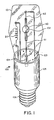
- Figure 1 shows a composite light source assembly 100, including a glass envelope 101 containing a quartz arc tube 60, having a top cathode electrode 62, lower anode electrode 61, and fill materials 102. Also within the envelope is auxiliary incandescent filament 20. Leads for all of the components are brought out through a pressed glass header and the envelope 101 is evacuated through exhaust tube 104.
- an enclosure 105 housing the electronic components constituting the ballast circuit shown in Figure 2.
- a screw base 106 allows the assembly 100 to replace directly a screw-in incandescent lamp.
- the electronic ballast circuit of the present invention is shown in Figure 2 and is connected to arc lamp 60 and incandescent filament 20.
- the ballast circuit includes rectifiers, a filament control circuit, and a switching current regulator.
- the switching current regulator is operational only after the arc lamp ignites and will be described last.
- silicon rectifier diodes 10, 11, 12 and 13 are connected in a bridge circuit with the output to an electrolytic type filter capacitor 14.
- a rectified and filtered DC voltage of about 165 V is produced between points 18 and 95.
- Arc discharge lamp 60 contains an anode electrode 61 and cathode 62. It is connected in series between points 18 and 95 with current sensing resistors 65 and 23 having resistances of a few ohms or less, inductor 50, and switching transistor 30. Transistor 30 is controlled by the driver circuit shown on the right in response to the voltages at points 18, 32, 33, and 34 as will be described later. Resistors 67 and 68 constitute a voltage divider network for sensing the voltage drop across the arc discharge lamp 60.
- the rectified voltage across the arc tube rises to the 165 V nominal output from the bridge rectifier, but its current is essentially zero before ignition.
- the filament control circuit has the dual purpose of igniting the arc discharge tube, bringing it through the glow-to-arc transition and providing auxiliary illumination by means of incandescent filament 20 while the arc lamp is warming up or while it is going through a hot restart cycle.
- the appropriate one of the three filament current modes is automatically selected according to the voltage drop across the arc tube, as sensed by the voltage divider comprised of resistors 67 and 68 and the current through the arc tube, as determined by the voltage drop developed across current sensing resistor 65.
- Diodes 15 and 16, along with diodes 12 and 13, comprise a second rectifier bridge assembly that provides an unfiltered, but full wave rectified direct current voltage between points 17 and 95.
- Auxiliary incandescent filament 20 and thyristor 70 are connected in series between points 17 and 95. Current through the filament is controlled by thyristor 70, which conducts depending on the nature of the gate current.
- a pulsing mode of operation of thyristor 70 takes place during the starting or hot restarting phases of arc lamp operation.
- Prior to starting the arc lamp current is essentially zero so that transistor 80 is nonconducting, but the voltage across the arc lamp is well above the approximately 60 V level at which transistor 90 conducts and the latter prevents resistor 73 from feeding a steady gate current to thyristor 70.
- a relaxation oscilator povides short current pulses at a rate of about 3 kHz to the gate of thyristor 70 which, as will be seen, eventually causes the arc lamp 60 to ignite.
- capacitor 63 is charged through resistor 74 and when its voltage reaches the breakdown potential (normally 32V) of diac 64, it discharges through the gate of thyristor 70 causing it to conduct a pulse of current as it abruptly discharges capacitor 72 through inductor winding 51 which resonate at a frequency from 10 to 20 kHz.
- inductor 51 and capacitor 72 As the oscillatory current in inductor 51 and capacitor 72 reverses phase, the current through filament 20 is diverted momentarily from thyristor 70 through the resonant circuit, and the thyristor is commuted to the OFF state. During that portion of the switching cycle when thyristor 70 is off, current through filament 20 and diode 16 charges capacitor 72 to about 150 V via inductor 51. Each time thyristor 70 is turned on, capacitor 72 is abruptly discharged through inductor 51 and continues to ring at an oscillatory frequency of from 10 to 20 kHz or several times that of the switching drive. Inductors 50 and 51 consist of two windings on a common laminated iron core.
- a high positive voltage pulse is applied to anode 61 of the arc tube 60.
- Diode 28 completes the circuit.
- a 1200 V pulse is produced when the 150 V on capacitor 72 is discharged.
- a turns ratio of 10:1 gives a 1500 V pulse.
- a sequence of these high voltage pulses is applied to arc discharge lamp 60 at a rate of about 3 kHz.
- Each oscillatory cycle eventually ignites arc discharge tube 60, which then begins to glow. It continues to glow on each succeeding oscillatory transient until it passes from the glow mode, where its voltage drop is high, about 200 V, and its current is low, less than 0.1 amp, to the arc beginning mode, where it begins to receive power through the switching transistor 30.
- This starting arrangement is operative for both cold starts and hot restarts.
- a cold start is fairly rapid but during a hot restart cycle the arc lamp requires several minutes to cool down before the starting pulses can reignite it.
- some auxiliary illumination is required from the incandescent filament, but during the pulsing mode of thyristor operation, the average current through the filament 20 is too low to produce any light.
- the arc lamp Upon ignition or reignition the arc lamp enters the initial warm-up stages of the arc mode.
- the driver circuit is now operational as will be described later.
- the voltage across the arc lamp is low, dropping well below 60 V to about 20 V.
- Lamp current is greater than about 0.1 amp and begins to flow through current sensing resistor 65, and through resistor 78 to the base of transistor 80 which conducts, thereby shunting the currents through resistors 74 and 75 to common point 95.
- the high arc lamp current stops the generation of lamp ignition pulses and the steady conduction of the thyristor on alternate half-cycles of the power line.
- transistor 90 turns off, allowing a steady filtered direct current to flow through resistors 73 and 77 to the gate of thyristor 70, and the auxiliary incandescent filament 20 lights at full brilliance as it now conducts current on both half-cycles of the input power line. This is the second mode of filament operation.
- Resistor 66 provides a steady load for the gate control circuitry to prevent gate triggering on small leakage currents.
- Capacitor 91 acts as an integrating capacitor to average out voltage fluctuations on the voltage sensed across the arc lamp 60.
- the switching current regulator includes a NPN darlington transistor 30, and a driver circuit for switching transistor 30 on and off in response to the magnitude of the current sensed in the form of the voltage drop across resistor 23.
- transistor 30 When transistor 30 is switched on, current from the rectifier output point 18 flows through it and resistors 23 and 65, inductor 50 and the arc discharge tube 60, increasing in magnitude until a predetermined high limit is reached, as shown in Figure 3.
- the driver circuit then switches transistor 30 off and the current decreases, although continuing to flow, but now flows through diode 28, driven by the energy previously stored in inductor 50.
- resistors 23 and 65, inductor 50 and the discharge tube 60 decrease to a predetermined low limit, the driver circuit again turns on transistor 30 and the oscillatory cycle repeats.
- transistor switch 30 When transistor switch 30 is off, the full DC output voltage of the bridge rectifier appears across points 18 and 34, thereby charging capacitor 41 through diode 42. This charge which is isolated by diode 42 during the on cycle of transistor 30 serves to supply base current drive through resistors 37 and 36 to the base of transistor 30. Transistor 45 shunts this base current to ground, point 34 during those portions of the switching cycle when transistor switch 30 is to be off. Transistor 45 begins conduction when the voltage drop across current sensing resistor 23 reaches the forward base to emitter junction voltage of transistor 45. At that point current begins to flow through resistor 46 into the base of transistor 45. This causes shunting of the base drive to transistor 30 which begins to turn off.
- the rising voltage at point 18 is coupled through capacitor 40 and resistors 38 and 39, and also to the base of transistor 45, which completely shunts off all of the base drive to transistor 30.
- the two transistors thereby constitute a bistable flip-flop, which switches transistor 30 between cut-off and saturation.
- the flyback current driven through diode 28 and resistor 23 by the energy stored in inductor 50 decreases, the voltage drop across resistor 23 drops to a point where the combined base drive signal of transistor 45 from resistors 46 and 39 no longer exceeds the base to emitter junction drop of transistor 45.
- transistor 30 again turns on and the switching cycle repeats.
- Zener diode 43 regulates the feedback voltage applied to resistor 39 from resistor 38 and keeps the current switching levels from being dependent upon the power supply output voltage. This provides an operation at a constant average lamp current over a wide range of line input voltages. Very little power is lost in the current sensing resistors and inductor, and the arc lamp thus operates with a very high efficiency.
Claims (5)
Applications Claiming Priority (2)
| Application Number | Priority Date | Filing Date | Title |
|---|---|---|---|
| US352675 | 1982-02-26 | ||
| US06/352,675 US4399392A (en) | 1982-02-26 | 1982-02-26 | Arc lamp power supply |
Publications (2)
| Publication Number | Publication Date |
|---|---|
| EP0091728A1 EP0091728A1 (de) | 1983-10-19 |
| EP0091728B1 true EP0091728B1 (de) | 1989-01-18 |
Family
ID=23386042
Family Applications (1)
| Application Number | Title | Priority Date | Filing Date |
|---|---|---|---|
| EP83301035A Expired EP0091728B1 (de) | 1982-02-26 | 1983-02-25 | Quelle für Entladungslampe |
Country Status (5)
| Country | Link |
|---|---|
| US (1) | US4399392A (de) |
| EP (1) | EP0091728B1 (de) |
| JP (1) | JPS5978494A (de) |
| CA (1) | CA1207014A (de) |
| DE (1) | DE3379024D1 (de) |
Cited By (1)
| Publication number | Priority date | Publication date | Assignee | Title |
|---|---|---|---|---|
| US20140015416A1 (en) * | 2012-07-11 | 2014-01-16 | Zoltan Somogyvari | Lamp driving module |
Families Citing this family (11)
| Publication number | Priority date | Publication date | Assignee | Title |
|---|---|---|---|---|
| US4464607A (en) * | 1981-09-25 | 1984-08-07 | General Electric Company | Lighting unit |
| US4473779A (en) * | 1982-05-26 | 1984-09-25 | Area Lighting Research, Inc. | Power factor measuring cut-off arrangement for and method of protecting a ballast-starter circuit from high pressure sodium lamp cycling malfunction |
| US4749913A (en) * | 1987-04-17 | 1988-06-07 | General Electric Company | Operating circuit for a direct current discharge lamp |
| US5047694A (en) * | 1989-06-30 | 1991-09-10 | Hubbell Incorporated | Lamp starting circuit |
| US5369340A (en) * | 1992-10-29 | 1994-11-29 | North American Philips Corporation | Driving scheme for a high intensity discharge ballast down converter |
| US5319286A (en) * | 1992-10-29 | 1994-06-07 | North American Philips Corporation | Ignition scheme for a high intensity discharge ballast |
| US5629844A (en) * | 1995-04-05 | 1997-05-13 | International Power Group, Inc. | High voltage power supply having multiple high voltage generators |
| GB2326543B (en) * | 1997-06-19 | 1999-12-08 | Toshiba Lighting & Technology | Lighting apparatus |
| US6674249B1 (en) * | 2000-10-25 | 2004-01-06 | Advanced Lighting Technologies, Inc. | Resistively ballasted gaseous discharge lamp circuit and method |
| US8228002B2 (en) * | 2008-09-05 | 2012-07-24 | Lutron Electronics Co., Inc. | Hybrid light source |
| US8008866B2 (en) * | 2008-09-05 | 2011-08-30 | Lutron Electronics Co., Inc. | Hybrid light source |
Family Cites Families (10)
| Publication number | Priority date | Publication date | Assignee | Title |
|---|---|---|---|---|
| US3517254A (en) * | 1968-05-14 | 1970-06-23 | Esquire Inc | Continuous lighting system for gaseous-discharge lamps with incandescent lights for standby |
| US3737720A (en) * | 1971-08-02 | 1973-06-05 | Gen Electric | Lighting system with auxiliary lamp control circuit |
| US4091307A (en) * | 1972-03-06 | 1978-05-23 | Esquire, Inc. | Emergency lighting system for gaseous-discharge lamps |
| US4005331A (en) * | 1973-06-19 | 1977-01-25 | Current Industries, Inc. | High intensity discharge lamp with auxiliary light |
| US3873882A (en) * | 1973-10-05 | 1975-03-25 | Leviton Manufacturing Co | Auxiliary lighting system for a gaseous discharge lamp |
| US4047076A (en) * | 1974-01-02 | 1977-09-06 | Esquire, Inc. | Emergency lighting system for gaseous discharge lamps |
| US4151445A (en) * | 1978-02-15 | 1979-04-24 | General Electric Company | Instant light lamp control circuit |
| US4170744A (en) * | 1978-03-10 | 1979-10-09 | General Electric Company | Combination discharge-incandescent lamp with thermal switch control |
| US4350930A (en) * | 1979-06-13 | 1982-09-21 | General Electric Company | Lighting unit |
| US4278916A (en) * | 1979-12-03 | 1981-07-14 | Gte Laboratories Incorporated | Instant-on light source |
-
1982
- 1982-02-26 US US06/352,675 patent/US4399392A/en not_active Expired - Lifetime
-
1983
- 1983-02-11 CA CA000421455A patent/CA1207014A/en not_active Expired
- 1983-02-25 JP JP58029634A patent/JPS5978494A/ja active Pending
- 1983-02-25 EP EP83301035A patent/EP0091728B1/de not_active Expired
- 1983-02-25 DE DE8383301035T patent/DE3379024D1/de not_active Expired
Cited By (1)
| Publication number | Priority date | Publication date | Assignee | Title |
|---|---|---|---|---|
| US20140015416A1 (en) * | 2012-07-11 | 2014-01-16 | Zoltan Somogyvari | Lamp driving module |
Also Published As
| Publication number | Publication date |
|---|---|
| US4399392A (en) | 1983-08-16 |
| DE3379024D1 (en) | 1989-02-23 |
| CA1207014A (en) | 1986-07-02 |
| EP0091728A1 (de) | 1983-10-19 |
| JPS5978494A (ja) | 1984-05-07 |
Similar Documents
| Publication | Publication Date | Title |
|---|---|---|
| US4700113A (en) | Variable high frequency ballast circuit | |
| CA1155169A (en) | Arc discharge lamp unit having an incandescent series filament ballast | |
| US5321337A (en) | Ballast having starting current restraint circuitry for preventing a large in-rush current and protection circuitry for preventing damage due to a start-up failure | |
| US4132925A (en) | Direct current ballasting and starting circuitry for gaseous discharge lamps | |
| US20070152598A1 (en) | Method for increasing profit in a business to maintain lighting operations in an office building or other place of business | |
| US4937501A (en) | Circuit arrangement for starting a high-pressure gas discharge lamp | |
| US5262699A (en) | Starting and operating circuit for arc discharge lamp | |
| US7239089B2 (en) | Power supply apparatus for high pressure discharge lamp | |
| EP1286574B1 (de) | Vorschaltgerät mit effizienter Elektroden-Vorheizung und Lampenfehlerschutz | |
| EP0091728B1 (de) | Quelle für Entladungslampe | |
| JPS5927079B2 (ja) | 瞬時照明ランプの制御回路 | |
| US6700331B2 (en) | Control circuit for dimming fluorescent lamps | |
| EP0132008B1 (de) | Mit einem Wechselrichter ausgerüstete Energieversorgungseinrichtung zum Entzünden und Speisen von Gas- und/oder Dampfentladungslampen | |
| US6091208A (en) | Lamp ignitor for starting conventional hid lamps and for starting and restarting hid lamps with hot restrike capability | |
| US5430354A (en) | HID lamp and auxiliary lamp ballast using a single multiple function switch | |
| US5138235A (en) | Starting and operating circuit for arc discharge lamp | |
| US4398130A (en) | Arc lamp lighting unit with low and high light levels | |
| US4382210A (en) | Ballast circuit for direct current arc lamp | |
| US4376911A (en) | Circuit system for lighting a discharge lamp or lamps | |
| US5426346A (en) | Gas discharge lamp ballast circuit with reduced parts-count starting circuit | |
| US5208515A (en) | Protection circuit for stabilizer for discharge apparatus | |
| JPH01134899A (ja) | ガス放電灯点孤及び給電用dc/acコンバータ | |
| US4937498A (en) | DC/AC converter for igniting and supplying a gas discharge lamp | |
| US4092564A (en) | Discharge lamp operating circuit | |
| US4045709A (en) | Discharge lamp operating circuit |
Legal Events
| Date | Code | Title | Description |
|---|---|---|---|
| PUAI | Public reference made under article 153(3) epc to a published international application that has entered the european phase |
Free format text: ORIGINAL CODE: 0009012 |
|
| 17P | Request for examination filed |
Effective date: 19830309 |
|
| AK | Designated contracting states |
Designated state(s): DE FR GB NL |
|
| 17Q | First examination report despatched |
Effective date: 19860117 |
|
| R17C | First examination report despatched (corrected) |
Effective date: 19870202 |
|
| GRAA | (expected) grant |
Free format text: ORIGINAL CODE: 0009210 |
|
| AK | Designated contracting states |
Kind code of ref document: B1 Designated state(s): DE FR GB NL |
|
| PG25 | Lapsed in a contracting state [announced via postgrant information from national office to epo] |
Ref country code: FR Free format text: THE PATENT HAS BEEN ANNULLED BY A DECISION OF A NATIONAL AUTHORITY Effective date: 19890118 |
|
| REF | Corresponds to: |
Ref document number: 3379024 Country of ref document: DE Date of ref document: 19890223 |
|
| PG25 | Lapsed in a contracting state [announced via postgrant information from national office to epo] |
Ref country code: GB Effective date: 19890318 |
|
| EN | Fr: translation not filed | ||
| PG25 | Lapsed in a contracting state [announced via postgrant information from national office to epo] |
Ref country code: NL Effective date: 19890901 |
|
| NLV4 | Nl: lapsed or anulled due to non-payment of the annual fee | ||
| PG25 | Lapsed in a contracting state [announced via postgrant information from national office to epo] |
Ref country code: DE Effective date: 19891101 |
|
| GBPC | Gb: european patent ceased through non-payment of renewal fee | ||
| PLBE | No opposition filed within time limit |
Free format text: ORIGINAL CODE: 0009261 |
|
| STAA | Information on the status of an ep patent application or granted ep patent |
Free format text: STATUS: NO OPPOSITION FILED WITHIN TIME LIMIT |
|
| 26N | No opposition filed |