EP0091353B1 - Method and apparatus for increasing and realizing heat exchanges on a pulverulent material having a large granulometric distribution - Google Patents
Method and apparatus for increasing and realizing heat exchanges on a pulverulent material having a large granulometric distribution Download PDFInfo
- Publication number
- EP0091353B1 EP0091353B1 EP83400637A EP83400637A EP0091353B1 EP 0091353 B1 EP0091353 B1 EP 0091353B1 EP 83400637 A EP83400637 A EP 83400637A EP 83400637 A EP83400637 A EP 83400637A EP 0091353 B1 EP0091353 B1 EP 0091353B1
- Authority
- EP
- European Patent Office
- Prior art keywords
- tube
- base
- column
- collector
- grate
- Prior art date
- Legal status (The legal status is an assumption and is not a legal conclusion. Google has not performed a legal analysis and makes no representation as to the accuracy of the status listed.)
- Expired
Links
Images

Classifications
-
- F—MECHANICAL ENGINEERING; LIGHTING; HEATING; WEAPONS; BLASTING
- F28—HEAT EXCHANGE IN GENERAL
- F28C—HEAT-EXCHANGE APPARATUS, NOT PROVIDED FOR IN ANOTHER SUBCLASS, IN WHICH THE HEAT-EXCHANGE MEDIA COME INTO DIRECT CONTACT WITHOUT CHEMICAL INTERACTION
- F28C3/00—Other direct-contact heat-exchange apparatus
- F28C3/10—Other direct-contact heat-exchange apparatus one heat-exchange medium at least being a fluent solid, e.g. a particulate material
- F28C3/12—Other direct-contact heat-exchange apparatus one heat-exchange medium at least being a fluent solid, e.g. a particulate material the heat-exchange medium being a particulate material and a gas, vapour, or liquid
- F28C3/16—Other direct-contact heat-exchange apparatus one heat-exchange medium at least being a fluent solid, e.g. a particulate material the heat-exchange medium being a particulate material and a gas, vapour, or liquid the particulate material forming a bed, e.g. fluidised, on vibratory sieves
Definitions
- French patent No. 2117314 describes a transport device, with cooling of cement particles; said transport is entirely carried out in apparently identical tubes and by a pneumatic transport tank.
- the reservoir is provided with an inlet for the product to be cooled and has a porous bottom which is ventilated by means of a connector and which is of convex shape. Through the porous bottom pass a number of compressed air lines which terminate in nozzles above which the tubes open.
- English Patent No. 1296057 describes a process in which the combustion of a liquid fuel is carried out and the combustion fumes (containing very fine unburnt particles) are sent in a bed composed of fluidized particles.
- the present invention intends to provide a solution to the problem of upward vertical transport and of a concomitant heat exchange of a pulverulent material having a spread distribution of its particle size.
- spread distribution of the grain size is meant a wider distribution than that which would be admissible for the pure and simple use of the fluidized bed technique.
- heat exchange is meant either reheating or, preferably, cooling of the material with essentially the outside.
- the method consists in carrying out, in the same enclosure, a fluidization of the pulverulent material, this fluidization being ensured up to a certain degree and flight of the part corresponding to said degree of said pulverulent material and a pneumatic drive of the remaining particles from the part bottom of the fluidized bed.
- the desired heat exchanges are carried out, on the one hand, on the fluidized bed and, on the other hand, on the pneumatic drive.
- the fluidization of the pulverulent material up to a certain degree in order to ensure the flight of the particles located inside said degree.
- up to a certain degree it is meant that one will predetermine the proportion of the pulverulent material introduced into the enclosure which will be fluidized and this according to the dimensions of the particles of said pulverulent material.
- the pulverulent material used has a Gaussian particle size distribution with particles of average dimensions of the order of 0.1 mm and particles of average dimensions of the order of 4 mm, we will decide to carry out the fluidization of all the particles of said material which will have average dimensions of less than 2 mm and a suitable enclosure and a flow rate of gasfluidizing agent will be used for this.
- said fluidization ensures the flight of said particles.
- a pneumatic drive device for these large particles is produced from this lower part.
- This pneumatic drive consists of an open tube into which, thanks to a suitable adjustment, an amount of air is introduced which is sufficient to entrain said large particles.
- This tube preferably crosses the fluidized bed and emerges from it
- the present invention therefore relates to a device for raising and cooling a finely divided material, the particle size of which extends over a large range, characterized in that it consists of a column provided at its base with a grid of fluidization, under which is provided a wind box and the upper part of which with a material collector, of an arrival of the material above said grid and of a central transfer tube whose base is located at a certain distance adjustable from a gas injection nozzle in the direction of the tube, said central tube opening into a sensor and auxiliary retarder itself connected to said manifold.
- the aforesaid nozzle is guided relative to the aforementioned fluidizing grid and constitutes a means of adjusting the distance separating it from the base of the central tube.
- a perforated plate 2 separates the interior volume 1a from the column of a wind box 3 connected to a source of compressed gas not shown.
- This perforated plate constitutes a fluidization grid above which, by a conduit 4, the divided product to be raised and cooled is brought.
- the upper part of column 1 is in communication, not shown, with a manifold 5 located at the desired altitude.
- This collector can be cyclone or other known type.
- a transfer tube 6 In the center of column 1, a transfer tube 6 has been placed, the base 6a of which communicates with the internal space 1a of the column. This base 6a is located at a distance d from a nozzle 7 for injecting an air stream into the tube.
- the upper end 6b of the tube 6 opens into an auxiliary sensor 8 which also acts as a retarder and which is itself connected to the main collector 5.
- the representation of the nozzle 7 is entirely schematic. It should be easily accessible to adjust said distance d but also its diameter and its location relative to the grid 2. It may also be advantageous for the tube 6 to be movable if one wishes to modify in another way the above distance.
- annular pipe 9 can be seen, the lower part of which is provided with orifices for spraying a liquid (water) for cooling the wall of the column 1, this water being collected by an annular tank 10 of drainage.
- Symbol 11 is a cooling device separate from the tube 6.
- the nozzle 7 can also be supplied by a source of compressed air independent of the wind box.
- a source of compressed air independent of the wind box.
- the product brought to the grid 2 being of a particle size distributed in a range (according to a distribution of gauss in particular), the pressure of the wind box is adjusted so that the main part of the grains is transported pneumatically in the column 6 at a speed determined by the cooling rate that is desired.
- the heaviest particles tend to remain in space 1 a, or even to concentrate at the level of grid 2.
- the suction effect described above creates a sweeping of this space with sufficient force to entrain these heavy particles which are rapidly propelled into the auxiliary sensor 8.
- the transfer is carried out at the expense of cooling, which can then be compensated, if necessary, by more vigorous cooling at 11 or by lengthening the length of the transfer channels.
- the percentage of particles concerned remaining low compared to the total product, the calorific incidence can be neglected.
- the invention finds an interesting application in the field of treatment of finely divided materials.
Abstract
Description
On a déjà préconisé de réaliser simultanément le transport vertical et des échanges thermiques sur un matériau pulvérulent en utilisant la technique du lit fluidisé. Mais, pour que les deux opérations puissent être simultanément effectuées avec une grande efficacité en employant ladite technique, il convient de n'avoir à manipuler qu'un matériau pulvérulent présentant une granulométrie à plage de distribution étroite. Dès que le matériau pulvérulent possède une granulométrie large, la technique du lit fluidisé présente des difficultés à la fois quant aux possibilités de transport du matériau et quant à la réalisation d'échanges thermiques convenables pour l'ensemble du matériau.It has already been recommended to carry out vertical transport and heat exchanges simultaneously on a pulverulent material using the fluidized bed technique. However, so that the two operations can be carried out simultaneously with great efficiency using the said technique, it is advisable to have to handle only a pulverulent material having a particle size with a narrow distribution range. As soon as the pulverulent material has a wide particle size, the fluidized bed technique presents difficulties both as regards the possibilities of transporting the material and as regards the achievement of suitable heat exchanges for the whole of the material.
Le brevet français No 2117314 décrit un dispositif de transport, avec refroidissement de particules de ciment; ledit transport est entièrement réalisé dans des tubes apparemment identiques et par un réservoir transporteur pneumatique. Le réservoir est pourvu d'une arrivée pour le produit à refroidir et présente un fond poreux qui est ventilé par l'intermédiaire d'un raccord et qui est de forme bombée. A travers le fond poreux passent un certain nombre de conduites d'air comprimé qui se terminent en buses au-dessus desquelles débouchent les tubes.French patent No. 2117314 describes a transport device, with cooling of cement particles; said transport is entirely carried out in apparently identical tubes and by a pneumatic transport tank. The reservoir is provided with an inlet for the product to be cooled and has a porous bottom which is ventilated by means of a connector and which is of convex shape. Through the porous bottom pass a number of compressed air lines which terminate in nozzles above which the tubes open.
Le brevet anglais No 1296057 décrit un procédé dans lequel on réalise la combustion d'un combustible liquide et on envoie les fumées de combustion (contenant de très fines particules imbrûlées) dans un lit composé de particules fluidifiées.English Patent No. 1296057 describes a process in which the combustion of a liquid fuel is carried out and the combustion fumes (containing very fine unburnt particles) are sent in a bed composed of fluidized particles.
Dans ces deux brevets antérieurs on ne fournit donc aucune solution au problème du transport, avec échange thermique, d'un matériau pulvérulent présentant une large distribution granulométrique.In these two prior patents, therefore, no solution is provided to the problem of transporting, with heat exchange, a pulverulent material having a wide particle size distribution.
La présente invention entend fournir une solution au problème du transport vertical ascendant et d'un échange thermique concomitant d'un matériau pulvérulent présentant une distribution étalée de sa granulométrie.The present invention intends to provide a solution to the problem of upward vertical transport and of a concomitant heat exchange of a pulverulent material having a spread distribution of its particle size.
Par distribution étalée de la granulométrie, on entend une distribution plus large que celle qui serait admissible pour l'utilisation pureetsimple de la technique du lit fluidisé.By spread distribution of the grain size is meant a wider distribution than that which would be admissible for the pure and simple use of the fluidized bed technique.
Par échange thermique, on entend soit le réchauffage, soit, de préférence, le refroidissement du matériau avec essentiellement l'extérieur.By heat exchange is meant either reheating or, preferably, cooling of the material with essentially the outside.
Le procédé consiste à réaliser, dans une même enceinte, une fluidisation du matériau pulvérulent, cette fluidisation étant assurée jusqu'à un certain degré et envol de la partie correspondant audit degré dudit matériau pulvérulent et un entraînement pneumatique des particules restantes à partir de la partie basse du lit fluidisé. Bien évidemment, les échanges thermiques recherchés sont réalisés, d'une part, sur le lit fluidisé et, d'autre part, sur l'entraînement pneumatique.The method consists in carrying out, in the same enclosure, a fluidization of the pulverulent material, this fluidization being ensured up to a certain degree and flight of the part corresponding to said degree of said pulverulent material and a pneumatic drive of the remaining particles from the part bottom of the fluidized bed. Obviously, the desired heat exchanges are carried out, on the one hand, on the fluidized bed and, on the other hand, on the pneumatic drive.
Il convient donc tout d'abord de réaliser la fluidisation du matériau pulvérulent jusqu'à un certain degré afin d'assurer l'envol des particules situées à l'intérieur dudit degré. Par jusqu'à un certain degré, on entend que l'on prédéterminera la proportion du matériau pulvérulent introduit dans l'enceinte qui sera fluidisé et cela en fonction des dimensions des particules dudit matériau pulvérulent. Ainsi, par exemple, si le matériau pulvérulent utilisé a une répartition granulométrique gaus- sienne avec des particules de dimensions moyennes de l'ordre de 0,1 mm et des particules de dimensions moyennes de l'ordre de 4 mm, on décidera de réaliser la fluidisation de toutes les particules dudit matériau qui auront des dimensions moyennss inférieures à 2 mm et on utilisera pour cela une enceinte et un débit de gazfluidisant convenables. De plus, il faut que ladite fluidisation assure l'envol desdites particules.It is therefore first of all necessary to carry out the fluidization of the pulverulent material up to a certain degree in order to ensure the flight of the particles located inside said degree. By up to a certain degree, it is meant that one will predetermine the proportion of the pulverulent material introduced into the enclosure which will be fluidized and this according to the dimensions of the particles of said pulverulent material. Thus, for example, if the pulverulent material used has a Gaussian particle size distribution with particles of average dimensions of the order of 0.1 mm and particles of average dimensions of the order of 4 mm, we will decide to carry out the fluidization of all the particles of said material which will have average dimensions of less than 2 mm and a suitable enclosure and a flow rate of gasfluidizing agent will be used for this. In addition, it is necessary that said fluidization ensures the flight of said particles.
Lorsque l'on réalise une fluidisation de ce type, il se trouve que les plus grosses particules (celles dont les dimensions moyennes sont comprises entre environ 2 et 4 mm dans l'exemple ci-dessus) restent dans l'enceinte et très généralement se déplacent dans la partie basse du lit fluidisé. Selon l'invention, on réalise à partir de cette partie basse un dispositif d'entraînement pneumatique de ces grosses particules. Cet entraînement pneumatique est constitué d'un tube ouvert dans lequel, grâce à un ajustage convenable, on introduit une quantité d'air suffisante pour entraîner lesdites grosses particules. Ce tube traverse de préférence le lit fluidisé et débouche hors de celui-ciWhen a fluidization of this type is carried out, it turns out that the largest particles (those whose average dimensions are between approximately 2 and 4 mm in the example above) remain in the enclosure and very generally move in the lower part of the fluidized bed. According to the invention, a pneumatic drive device for these large particles is produced from this lower part. This pneumatic drive consists of an open tube into which, thanks to a suitable adjustment, an amount of air is introduced which is sufficient to entrain said large particles. This tube preferably crosses the fluidized bed and emerges from it
En ce qui concerne les échanges thermiques que l'on réalise sur les particules, il va de soi que ces échanges sont effectués, d'une part, au niveau du litfluidisé pour toutes les particules situées dans ce lit (et tous les moyens connus et utilisables pour réaliser des échanges thermiques sur les lits fluidi- sés peuvent être mis en oeuvre) et, d'autre part, au niveau du dispositif d'entraînement pneumatique, dans la partie dudit dispositif située hors du lit fluidisé, pour les particules entraînées par le dispositif pneumatique. Cette possibilité de réaliser les échanges thermiques à deux niveaux est intéressante car lesdits échanges peuvent être spécialement adaptés en tenant compte des dimensions des particules qui doivent subir ces échanges.With regard to the heat exchanges which are carried out on the particles, it goes without saying that these exchanges are carried out, on the one hand, at the level of the fluidized bed for all the particles located in this bed (and all known means and can be used to carry out heat exchanges on the fluidized beds can be implemented) and, on the other hand, at the pneumatic drive device, in the part of said device located outside the fluidized bed, for the particles entrained by the pneumatic device. This possibility of carrying out heat exchanges at two levels is advantageous because said exchanges can be specially adapted taking into account the dimensions of the particles which must undergo these exchanges.
La présente invention concerne donc un dispositif d'élévation et de refroidissement d'un matériau finement divisé dont la granulométrie s'étend sur une plage importante, caractérisé en ce qu'il est constitué par une colonne pourvue à sa base d'une grille de fluidisation, sous laquelle est ménagée une boîte à vent et dont la partie supérieure avec un collecteur du matériau, d'une arrivée du matériau au-dessus de ladite grille et d'un tube central de transfert dont la base est située à une certaine distance réglable d'une buse d'injection de gaz en direction du tube, ledit tube central débouchant dans un capteur et ralentisseur auxiliaire lui-même connecté audit collecteur.The present invention therefore relates to a device for raising and cooling a finely divided material, the particle size of which extends over a large range, characterized in that it consists of a column provided at its base with a grid of fluidization, under which is provided a wind box and the upper part of which with a material collector, of an arrival of the material above said grid and of a central transfer tube whose base is located at a certain distance adjustable from a gas injection nozzle in the direction of the tube, said central tube opening into a sensor and auxiliary retarder itself connected to said manifold.
De manière préférée, la buse susdite est guidée par rapport à la grille de fluidisation susdite de manière libre et constitue un moyen de réglage de la distance la séparant de la base du tube central.Preferably, the aforesaid nozzle is guided relative to the aforementioned fluidizing grid and constitutes a means of adjusting the distance separating it from the base of the central tube.
On notera:
- - d'une part, que l'arrivée du matériau dans la colonne doit être convenablement positionnée et éventuellement aménagée pour que les particules soient soumises au flux gazeux de fluidisation avant d'atteindre le tube central d'entraînement pneumatique,
- - d'autre part, que la paroi extérieure de la colonne est équipée d'un système de refroidissement qui peut être par pulvérisation d'eau, tandis que le tube central peut également être équipé d'un système de refroidissement séparé.
- - on the one hand, that the arrival of the material in the column must be suitably positioned and possibly arranged so that the particles are subjected to the fluidizing gas flow before reaching the central pneumatic drive tube,
- - on the other hand, that the outer wall of the column is equipped with a cooling system which can be by spraying with water, while the central tube can also be equipped with a separate cooling system.
L'invention sera mieux comprise au cours de la description donnée ci-après à titre d'exemple purement indicatif et non limitatif qui permettra d'en dégager les avantages et les caractéristiques secondaires.The invention will be better understood during the description given below by way of purely indicative and nonlimiting example which will make it possible to identify the advantages and the secondary characteristics thereof.
Il sera fait référence aux dessins annexés, dans lesquels:
- la fig. 1 est un schéma de principe de l'invention;
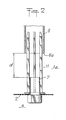
- la fig. 2 est une vue de détail de la fig. 1.
- fig. 1 is a block diagram of the invention;
- fig. 2 is a detailed view of FIG. 1.
En se reportant tout d'abord à la fig. 1, on voit une colonne 1 à la base de laquelle une plaque perforée 2 sépare le volume intérieur 1 a de la colonne d'une boîte à vent 3 connectée à une source de gaz comprimé non représentée. Cette plaque perforée constitue une grille de fluidisation au-dessus de laquelle, par un conduit 4, le produit divisé à élever et refroidir est amené. La partie supérieure de la colonne 1 est en communication de manière non représentée avec un collecteur 5 situé à l'altitude désirée. Ce collecteur peut être tu type cyclone ou autre connu.Referring first to FIG. 1, we see a column 1 at the base of which a
Au centre de la colonne 1, on a disposé un tube de transfert 6 dont la base 6a communique avec l'espace interne 1 a de la colonne. Cette base 6a est située à une distance d d'une buse 7 d'injection d'une veine d'air dans le tube. L'extrémité supérieure 6b du tube 6 débouche dans un capteur auxiliaire 8 qui fait également office de ralentisseur et qui est lui-même connecté au collecteur principal 5. La représentantion de la buse 7 est tout à fait schématique. Il convient que celle-ci soit facilement accessible pour régler ladite distance d mais également son diamètre et sa situation par rapport à la grille 2. Il peut également être intéressant que le tube 6 soit mobile si l'on veut modifier d'une autre manière la distance d susdite.In the center of column 1, a
Enfin, sur cette figure, on voit une canalisation annulaire 9 dont la partie inférieure est pourvue d'orifices de pulvérisation d'un liquide (eau) de refroidissement de la paroi de la colonne 1, cette eau étant recueillie par un bac annulaire 10 de drainage. On a symbolié en 11 un dispositif de refroidissement séparé du tube 6.Finally, in this figure, an annular pipe 9 can be seen, the lower part of which is provided with orifices for spraying a liquid (water) for cooling the wall of the column 1, this water being collected by an
Sur la fig. 2, qui est une vue de détail d'un mode de réalisation de la fig. 1, au niveau de la grille de fluidisation et du tube 6, on retrouve certains des éléments déjà décrits avec les mêmes références. On voit sur cette figure que la buse 7 est axialement alignée avec le tube 6 (des guides 12 permettent de garder cet alignement). Elle met en communication directe la boîte à vent 3 avec l'intérieur 1 a de la colonne. Comme la perte de charge de la buse est beaucoup plus faible que celle de la grille 2, il se produit un flux d'air ou de gaz qui atteint la base 6a du tube 6 en créant une aspiration de l'atmosphère ambiante autour des éléments 6 et 7. En réglant la distance d séparant l'extrémité de la buse de l'extrémité du tube 6, on règle l'effet d'aspiration et donc le rôle du tube 6. Ce réglage est avantageusement réalisé en montant sur la grille 2 des buses de différentes longueurs axiales. On peut également alimenter la buse 7 par une source d'air comprimé indépendante de la boîte à vent. On peut également prévoir sans sortir du cadre de l'invention tout autre système de buse 7 accessible directement par l'extérieur et dont il est possible également de faire varier le diamètre pour un réglage du fonctionnement de l'appareil.In fig. 2, which is a detailed view of an embodiment of FIG. 1, at the fluidization grid and the
Le produit amené sur la grille 2 étant d'une granulométrie répartie dans une fourchette (selon une répartition de gauss notamment), on règle la pression de la boîte à vent de manière que la principale partie des grains soit transportée pneumatique- ment dans la colonne 6 selon une vitesse déterminée par le taux de refroidissement que l'on désire. Mais les particules les plus lourdes ont tendance à rester dans l'espace 1 a, voire à se concentrer au niveau de la grille 2. L'effet d'aspiration décrit ci-dessus crée un balayage de cet espace d'une force suffisante pour entraîner ces particules lourdes qui sont rapidement propulsées dans le capteur auxiliaire 8.The product brought to the
Pour ces particules lourdes, le transfert est réalisé au détriment du refroidissement, ce qui peut être ensuite compensé, si nécessaire, par un refroidissement plus énergique en 11 ou en allongeant la longueur des canaux de transfert. En tout état de cause, le pourcentage des particules concerné restant faible par rapport à la totalité du produit, l'incidence calorifique peut être négligée.For these heavy particles, the transfer is carried out at the expense of cooling, which can then be compensated, if necessary, by more vigorous cooling at 11 or by lengthening the length of the transfer channels. In any event, the percentage of particles concerned remaining low compared to the total product, the calorific incidence can be neglected.
L'invention trouve une application intéressante dans le domaine du traitement des matières finement divisées.The invention finds an interesting application in the field of treatment of finely divided materials.
Claims (4)
Priority Applications (1)
| Application Number | Priority Date | Filing Date | Title |
|---|---|---|---|
| AT83400637T ATE14924T1 (en) | 1982-04-02 | 1983-03-28 | METHOD AND DEVICE FOR LIFTING AND REALIZING HEAT EXCHANGE FOR POWDERY MATERIAL WITH A WIDE GRANULOMETRIC DISTRIBUTION. |
Applications Claiming Priority (2)
| Application Number | Priority Date | Filing Date | Title |
|---|---|---|---|
| FR8205806 | 1982-04-02 | ||
| FR8205806A FR2524439A1 (en) | 1982-04-02 | 1982-04-02 | DEVICE FOR LIFTING AND COOLING A DIVIDED MATERIAL WITH VARIABLE GRANULOMETRY |
Publications (2)
| Publication Number | Publication Date |
|---|---|
| EP0091353A1 EP0091353A1 (en) | 1983-10-12 |
| EP0091353B1 true EP0091353B1 (en) | 1985-08-14 |
Family
ID=9272719
Family Applications (1)
| Application Number | Title | Priority Date | Filing Date |
|---|---|---|---|
| EP83400637A Expired EP0091353B1 (en) | 1982-04-02 | 1983-03-28 | Method and apparatus for increasing and realizing heat exchanges on a pulverulent material having a large granulometric distribution |
Country Status (5)
| Country | Link |
|---|---|
| EP (1) | EP0091353B1 (en) |
| AT (1) | ATE14924T1 (en) |
| DE (1) | DE3360551D1 (en) |
| ES (1) | ES521075A0 (en) |
| FR (1) | FR2524439A1 (en) |
Families Citing this family (1)
| Publication number | Priority date | Publication date | Assignee | Title |
|---|---|---|---|---|
| CN104634134B (en) * | 2014-12-10 | 2016-06-22 | 新奥科技发展有限公司 | Fluidized bed cooler, cooling means and coal hydrogenation gasification system |
Family Cites Families (7)
| Publication number | Priority date | Publication date | Assignee | Title |
|---|---|---|---|---|
| NL87455C (en) * | 1953-12-31 | |||
| DE1082607B (en) * | 1956-11-09 | 1960-06-02 | Metallgesellschaft Ag | Device for cooling hot, small items |
| FR1350734A (en) * | 1962-12-04 | 1964-01-31 | Improvements to heat exchangers | |
| DE1551424A1 (en) * | 1967-06-29 | 1970-10-29 | Franz Jos Waeschle Fa | Method and device for cooling powdery goods |
| GB1296057A (en) * | 1969-07-09 | 1972-11-15 | ||
| DE2059575A1 (en) * | 1970-12-03 | 1972-06-15 | Polysius Ag | Device for cooling fine material, in particular cement |
| GB1439861A (en) * | 1973-05-08 | 1976-06-16 | Atomic Energy Authority Uk | Fluidised bed apparatus |
-
1982
- 1982-04-02 FR FR8205806A patent/FR2524439A1/en active Granted
-
1983
- 1983-03-28 EP EP83400637A patent/EP0091353B1/en not_active Expired
- 1983-03-28 AT AT83400637T patent/ATE14924T1/en not_active IP Right Cessation
- 1983-03-28 DE DE8383400637T patent/DE3360551D1/en not_active Expired
- 1983-03-29 ES ES521075A patent/ES521075A0/en active Granted
Also Published As
| Publication number | Publication date |
|---|---|
| FR2524439A1 (en) | 1983-10-07 |
| EP0091353A1 (en) | 1983-10-12 |
| ES8404660A1 (en) | 1984-05-16 |
| ES521075A0 (en) | 1984-05-16 |
| DE3360551D1 (en) | 1985-09-19 |
| FR2524439B1 (en) | 1984-07-13 |
| ATE14924T1 (en) | 1985-08-15 |
Similar Documents
| Publication | Publication Date | Title |
|---|---|---|
| EP0759320B1 (en) | Apparatus for separating gas by adsorption | |
| EP0755720B1 (en) | Device for spraying a liquid | |
| FR2484280A1 (en) | FLUIDIZED BED REACTOR AND METHOD FOR COMBUSTING MATERIALS CONTAINING INCOMBUSTIBLE SUBSTANCES USING THE SAME | |
| EP0008270B1 (en) | Method and apparatus for pneumatically conveying loose material | |
| EP0189709A1 (en) | Pneumatic powder injector | |
| EP0521794A1 (en) | Apparatus for storing and conveying ice-balls, without sticking to each other, from their place of production to their place of use, where they are propelled against a target | |
| FR2617832A1 (en) | SPHERULIZATION OVEN AND METHOD FOR MANUFACTURING GLASS PEARLS | |
| FR2724217A1 (en) | DEVICE FOR SPREADING A FLAME BY COANDA EFFECT AND OVEN COMPRISING THIS DEVICE | |
| EP0006805B1 (en) | Apparatus for the distribution of solid particles | |
| FR2584175A1 (en) | PROCESS AND FIXED COOLER FOR COOLING GRANULAR MATERIAL | |
| EP0091353B1 (en) | Method and apparatus for increasing and realizing heat exchanges on a pulverulent material having a large granulometric distribution | |
| EP0772003B1 (en) | Device for drawing off a gas through a conduit for venting it | |
| CH656074A5 (en) | INSTALLATION FOR INJECTING A POWDERY MATERIAL, ESPECIALLY AN ADSORBENT MATERIAL, INTO A CONTACT COLUMN. | |
| FR2745074A1 (en) | DEVICE FOR REDUCING THE WATER CONTENT OF LIGNITE CONTAINING WATER | |
| EP0356308A1 (en) | Fluidising gas supply device for the openings of a fluidised-bed support | |
| EP0225221B1 (en) | Device for feeding the openings of a fluidization grid with an unclogging gas | |
| EP0068958A1 (en) | Steam generator with a dynamic discharge system | |
| FR2543456A1 (en) | Method and device for the gravimetric and aerodynamic separation of a heterogeneous mixture of objects comprising products and wastes whose respective densities differ from each other | |
| EP0002402A1 (en) | Suction cleaner with double filtration | |
| FR2473349A1 (en) | PROCESS FOR SEPARATING THE LIQUID FROM A MIXTURE OF GAS AND LIQUID AND SEPARATOR FOR CARRYING OUT SAID METHOD | |
| EP2755800A1 (en) | Device for spraying dry ice, particularly frozen carbon dioxide, and nozzle for said device | |
| FR2666143A1 (en) | DEVICE FOR EXHAUSTING GASES FOR VERTICAL LAUNCH MODULE OF MISSILES. | |
| EP0283625B1 (en) | Installation for aspiration of a particle-charged fluid, and vehicle equipped with this installation | |
| FR2670402A1 (en) | Cyclone comprising a flow straightener for the conversion of a swirling flux into a linear flow | |
| EP0094307A2 (en) | Jet mills |
Legal Events
| Date | Code | Title | Description |
|---|---|---|---|
| PUAI | Public reference made under article 153(3) epc to a published international application that has entered the european phase |
Free format text: ORIGINAL CODE: 0009012 |
|
| AK | Designated contracting states |
Designated state(s): AT BE CH DE FR GB IT LI LU NL SE |
|
| 17P | Request for examination filed |
Effective date: 19840320 |
|
| ITF | It: translation for a ep patent filed |
Owner name: JACOBACCI & PERANI S.P.A. |
|
| GRAA | (expected) grant |
Free format text: ORIGINAL CODE: 0009210 |
|
| AK | Designated contracting states |
Designated state(s): AT BE CH DE FR GB IT LI LU NL SE |
|
| REF | Corresponds to: |
Ref document number: 14924 Country of ref document: AT Date of ref document: 19850815 Kind code of ref document: T |
|
| REF | Corresponds to: |
Ref document number: 3360551 Country of ref document: DE Date of ref document: 19850919 |
|
| PG25 | Lapsed in a contracting state [announced via postgrant information from national office to epo] |
Ref country code: LU Free format text: LAPSE BECAUSE OF NON-PAYMENT OF DUE FEES Effective date: 19860331 |
|
| PLBE | No opposition filed within time limit |
Free format text: ORIGINAL CODE: 0009261 |
|
| STAA | Information on the status of an ep patent application or granted ep patent |
Free format text: STATUS: NO OPPOSITION FILED WITHIN TIME LIMIT |
|
| 26N | No opposition filed | ||
| PGFP | Annual fee paid to national office [announced via postgrant information from national office to epo] |
Ref country code: AT Payment date: 19870223 Year of fee payment: 5 |
|
| PGFP | Annual fee paid to national office [announced via postgrant information from national office to epo] |
Ref country code: NL Payment date: 19870331 Year of fee payment: 5 |
|
| PG25 | Lapsed in a contracting state [announced via postgrant information from national office to epo] |
Ref country code: AT Effective date: 19880328 |
|
| PG25 | Lapsed in a contracting state [announced via postgrant information from national office to epo] |
Ref country code: SE Effective date: 19880329 |
|
| PG25 | Lapsed in a contracting state [announced via postgrant information from national office to epo] |
Ref country code: LI Effective date: 19880331 Ref country code: CH Effective date: 19880331 |
|
| BERE | Be: lapsed |
Owner name: KREBS & CO. S.A. Effective date: 19880331 |
|
| PG25 | Lapsed in a contracting state [announced via postgrant information from national office to epo] |
Ref country code: NL Effective date: 19881001 |
|
| NLV4 | Nl: lapsed or anulled due to non-payment of the annual fee | ||
| PG25 | Lapsed in a contracting state [announced via postgrant information from national office to epo] |
Ref country code: GB Free format text: LAPSE BECAUSE OF NON-PAYMENT OF DUE FEES Effective date: 19881122 |
|
| GBPC | Gb: european patent ceased through non-payment of renewal fee | ||
| REG | Reference to a national code |
Ref country code: CH Ref legal event code: PL |
|
| PG25 | Lapsed in a contracting state [announced via postgrant information from national office to epo] |
Ref country code: DE Effective date: 19881201 |
|
| PG25 | Lapsed in a contracting state [announced via postgrant information from national office to epo] |
Ref country code: BE Effective date: 19890331 |
|
| EUG | Se: european patent has lapsed |
Ref document number: 83400637.1 Effective date: 19881206 |
|
| PGFP | Annual fee paid to national office [announced via postgrant information from national office to epo] |
Ref country code: FR Payment date: 20010112 Year of fee payment: 19 |
|
| PG25 | Lapsed in a contracting state [announced via postgrant information from national office to epo] |
Ref country code: FR Free format text: LAPSE BECAUSE OF NON-PAYMENT OF DUE FEES Effective date: 20021129 |
|
| REG | Reference to a national code |
Ref country code: FR Ref legal event code: ST |