EP0091186B1 - An improved reel servo system in a recording and/or reproducing apparatus - Google Patents
An improved reel servo system in a recording and/or reproducing apparatus Download PDFInfo
- Publication number
- EP0091186B1 EP0091186B1 EP83301014A EP83301014A EP0091186B1 EP 0091186 B1 EP0091186 B1 EP 0091186B1 EP 83301014 A EP83301014 A EP 83301014A EP 83301014 A EP83301014 A EP 83301014A EP 0091186 B1 EP0091186 B1 EP 0091186B1
- Authority
- EP
- European Patent Office
- Prior art keywords
- tape
- reel
- counter
- pulses
- counters
- Prior art date
- Legal status (The legal status is an assumption and is not a legal conclusion. Google has not performed a legal analysis and makes no representation as to the accuracy of the status listed.)
- Expired
Links
- 238000012545 processing Methods 0.000 claims description 16
- 230000004044 response Effects 0.000 claims description 7
- 238000000034 method Methods 0.000 claims description 5
- 230000003213 activating effect Effects 0.000 claims description 4
- 230000004913 activation Effects 0.000 claims description 3
- 230000002401 inhibitory effect Effects 0.000 claims description 3
- 238000009825 accumulation Methods 0.000 claims description 2
- 238000010586 diagram Methods 0.000 description 23
- 239000000872 buffer Substances 0.000 description 6
- 230000015654 memory Effects 0.000 description 6
- 230000002457 bidirectional effect Effects 0.000 description 4
- 238000004891 communication Methods 0.000 description 4
- 230000006870 function Effects 0.000 description 4
- 230000003993 interaction Effects 0.000 description 4
- 230000007704 transition Effects 0.000 description 4
- 230000008901 benefit Effects 0.000 description 2
- 230000008859 change Effects 0.000 description 2
- 239000002131 composite material Substances 0.000 description 2
- 230000000694 effects Effects 0.000 description 2
- 230000008569 process Effects 0.000 description 2
- 238000012360 testing method Methods 0.000 description 2
- 230000002463 transducing effect Effects 0.000 description 2
- 230000001133 acceleration Effects 0.000 description 1
- 239000003990 capacitor Substances 0.000 description 1
- 239000000919 ceramic Substances 0.000 description 1
- 230000000295 complement effect Effects 0.000 description 1
- 230000007423 decrease Effects 0.000 description 1
- 230000003247 decreasing effect Effects 0.000 description 1
- 238000005259 measurement Methods 0.000 description 1
- 238000012544 monitoring process Methods 0.000 description 1
- 238000012856 packing Methods 0.000 description 1
- 230000001960 triggered effect Effects 0.000 description 1
Images






Classifications
-
- G—PHYSICS
- G11—INFORMATION STORAGE
- G11B—INFORMATION STORAGE BASED ON RELATIVE MOVEMENT BETWEEN RECORD CARRIER AND TRANSDUCER
- G11B15/00—Driving, starting or stopping record carriers of filamentary or web form; Driving both such record carriers and heads; Guiding such record carriers or containers therefor; Control thereof; Control of operating function
- G11B15/02—Control of operating function, e.g. switching from recording to reproducing
- G11B15/026—Control of operating function, e.g. switching from recording to reproducing by using processor, e.g. microcomputer
-
- G—PHYSICS
- G11—INFORMATION STORAGE
- G11B—INFORMATION STORAGE BASED ON RELATIVE MOVEMENT BETWEEN RECORD CARRIER AND TRANSDUCER
- G11B15/00—Driving, starting or stopping record carriers of filamentary or web form; Driving both such record carriers and heads; Guiding such record carriers or containers therefor; Control thereof; Control of operating function
- G11B15/18—Driving; Starting; Stopping; Arrangements for control or regulation thereof
- G11B15/43—Control or regulation of mechanical tension of record carrier, e.g. tape tension
-
- G—PHYSICS
- G11—INFORMATION STORAGE
- G11B—INFORMATION STORAGE BASED ON RELATIVE MOVEMENT BETWEEN RECORD CARRIER AND TRANSDUCER
- G11B15/00—Driving, starting or stopping record carriers of filamentary or web form; Driving both such record carriers and heads; Guiding such record carriers or containers therefor; Control thereof; Control of operating function
- G11B15/18—Driving; Starting; Stopping; Arrangements for control or regulation thereof
- G11B15/46—Controlling, regulating, or indicating speed
- G11B15/467—Controlling, regulating, or indicating speed in arrangements for recording or reproducing wherein both record carriers and heads are driven
Definitions
- the present invention generally relates to servo systems for recording and reproducing apparatus and, more particularly, to a microprocessor controlled reel servo for a magnetic tape recording and reproducing apparatus.
- video recording and reproducing apparatus particularly, apparatus that records and reproduces video information of broadcast quality
- apparatus that records and reproduces video information of broadcast quality
- broadcast quality recording and reproducing apparatus particularly video tape recording and reproducing apparatus
- the level of technical sophistication is extraordinary in terms of the amount of control that is required to reliably operate the apparatus at broadcast quality standards.
- videotape recording apparatus have a number of servo systems which control their operation, including a servo system which controls the reel drive motors which drive the supply and take-up reels.
- the improved reel servo of the present invention is only one of the major servos of a recording and/or reproducing apparatus that are controlled by a single microprocessor
- the reel servo of the present invention contains many desirable functional features that are found in prior art reel servos, including microprocessor controlled reel servo systems.
- the use of a single microprocessor for controlling all of the major servos in the apparatus results in significant improvements in terms of the inherent communication between the various servos.
- the interaction of one servo with another in a more intimate manner also provides improved functional capabilities that are very difficult to implement using hardwired logic and other circuitry.
- a servo control system for a video recording and reproducing machine having a supply reel and a take-up reel for the transport of magnetic tape past a scanner, the control system comprising velocity sensors associated with each reel to provide respective pulses denoting the rotational velocity of the respective reel and a velocity sensor to provide independently of the capstan pulses denoting the longitudinal velocity of the tape, processing means for measuring the diameter of a tape pack on one of the reels and means for controlling the speed of the said one reel in response to the measured diameter of the tape pack, the processing means comprising two counters, the counters being arranged when activated to accumulate the pulses indicative of the longitudinal tape speed and being alternately cleared and activated in response to the rotational velocity denoting pulses from the respective one of the above mentioned reel velocity sensors, the clearing and activating of one counter interrupting the accumulation of pulses by the other counter, and the processing means being arranged to interrogate both counters and to use the larger accumulated count to determine the tape pack diameter.
- apparatus for determining the rotational speed of a reel relative to the longitudinal speed of a tape wrapped on the reel comprising: means for generating clock pulses having a frequency indicative of the longitudinal speed of the tape, means for generating control pulses having a frequency related to the rotational speed of the reel and processing means including a counter which counts the clock pulses and is cleared and activated by a control pulse, characterised in that the processing means comprises two counters which are alternately cleared and activated by the control pulses, the clearing and activation of either counter inhibiting counting of the clock pulses by the other counter and means for interrogating both counters and selecting the larger accumulated count.
- a method of determining the diameter of a tape pack on a reel which supplies or takes up take comprises generating clock pulses at a frequency representing the longitudinal speed of the tape; generating control pulses at a frequency representing the rotational velocity of the reel, and in response to the occurrence of a control pulse clearing a counter and causing the counter to count clock pulses, characterised by clearing and activating a second counter alternately with the first mentioned counter, inhibiting one counter from counting when the other is cleared and activated, and interrogating both counters to ascertain the larger of the two counts accumulated by the counters.
- One object of the present invention is to provide an improved reel servo of the foregoing type which utilizes longitudinal tape speed information together with reel tachometer information to instantaneously determine the diameter of tape wrapped on each of the reels.
- An associated object is to provide the diameter information in a novel way whereby it is instantaneously available to the microprocessor for control of the reel servo as well as other servos.
- the reel servo system of the present invention is controlled by a microprocessor which also controls the other major servo systems of a tape recording and reproducing apparatus, the other servos of which include: 1) a scanning drum servo which rotates the transducing head at the proper speed during operations; 2) a capstan servo which controls the movement of the tape during recording and during most, but not all reproducing operations; and, 3) the automatic scan tracking servo which controls the transverse movement relative to the longitudinal direction of the track of the reproduced head to have it accurately follow a track during reproducing and particularly during reproducing for special motion effects wherein the tape is being transported at a speed other than normal playback speed.
- the microprocessor receives digital information as well as digitally converted analog information from various locations throughout the circuitry and apparatus, processes such information and thereafter provides digital output signals to other circuitry, some signals of which are converted into the analog domain for controlling the various operations that are performed by the apparatus in its various modes.
- the nature of the operation of the other servos and the circuitry that carries out the operation thereof will not be specifically described herein, but such servos are comprehensively described in European Patent Application No. 83301016.8 entitled “Microprocessor Controlled Multiple Servo System for a Recording and/or Rerroducing Apparatus", filed on even date herewith.
- a microprocessor 30 which is interconnected by a data bus 31 with a reel servo 32, a capstan servo 34, a scanner servo 36 and a machine communication interface 38 which essentially controls the various modes of the recording and reproducing apparatus as manipulated by an operator or from a remote location.
- the microprocessor also interacts with a reference generator 40 which receives as an input thereto a reference station composite sync signal via line 42 and the reference generator generates system clocks which clock the microprocessor and which in turn synchronizes all of the clock timing of the servos and other circuitry.
- the microprocessor also interacts with the automatic scan tracking servo 44 and a tape sync processor 46 which has a tape composite sync signal input via line 48.
- the tape sync processor additionally provides a signal to the time base corrector interface 50 which provides appropriate timing and control signals for use by the time base corrector to provide a broadcast quality video image having the requisite stability and vertical position with respect to system reference as well as the correct chroma information, which processing varies depending upon what reproducing mode the apparatus is being operated.
- Fig. 1 illustrates the interaction of the microprocessor with the various servo systems of the apparatus, with machine control and with the time base corrector and the like
- the system can also be functionally described in terms of input and output signals that are provided to and from the microprocessor and this functional block diagram is shown in Fig. 2.
- the microprocessor 30 receives frequency, phase and timing data shown by the upper left functional block including such input signals as scanner tach pulses, reel tack pulses, capstan tach pulses, reference vertical and frame timing signals, which is converted into digital information for processing by the microprocessor.
- the microprocessor also receives analog information shown by the block left of the microprocessor which is converted into digital information for processing by the microprocessor and such analog input signals include the automatic scan tracking error signals, the tension arm error signals and various motor current signals from the reel drive motors, the capstan drive motor and the scanner drive motor.
- the data bus also receives operating mode information as well as other machine control data and it processes this information and provides status information and other data.
- the microprocessor generates digital information which is converted to analog information and these analog output signals include control signals for the capstan servo, the reel servo, the scanner servo and the automatic scan tracking servo.
- the microprocessor provides frequency, phase and timing output information which include delay signals, phase and timing output information that are used by the various servos and other circuits.
- the microprocessor controlled system of the present embodiment has a unique advantage in that it is adaptable for recording and reproducing video signals from any standard worldwide format, i.e., it can record and reproduce a NTSC signal having 525 lines or a PAL or SECAM signal having 625 horizontal lines.
- the input control line can be set to operate either as a 525 or 625 line system and the various constants and other software values which control the servos and other circuitry of the apparatus will be selected for proper operation.
- another control line can be set for either a PAL or SECAM format system once a 625 line system is specified.
- the software in memory includes instructions and numerical constants that will permit the apparatus to properly operate regardless of the television signal format that is being used.
- the microprocessor controlled servo system described herein is adapted to control the reel servo system and the scanner servo system during the high speed shuttle mode in a way so as to protect the recording and reproducing heads, while the tape is being wound off one of the reels onto the other.
- reel tape pack diameter information that is determined by the microprocessor is used to control the reel servo and the scanning drum servo to perform a sequence of events which substantially reduce if not eliminate the possibility of heads being chipped.
- the microprocessor determines that the tape has almost reached the end of being wound off of one reel, it controls the reel servo to stop the tape and it also reverses scanner motor current to brake the scanner. After the tape has been stopped, the reel servo moves the tape at a relatively slow rate, e.g., twice normal recording speed, and the scanning drum is allowed to coast while the tape is wound entirely off of one reel on to the other.
- a relatively slow rate e.g., twice normal recording speed
- the apparatus is programmed to operate in various operating modes as is shown in the broad flow chart of Fig. 3a.
- the flow chart representing microprocessor software shows that once the machine is initialized, a mode is selected and these modes include stop, record, slow and fast motion reproduce, stop motion or still frame reproduce, ready and normal play.
- each operating mode includes various subroutines which are called as shown in Fig. 3a. Certain ones of these subroutines are used in various ones of the operating modes.
- the play mode will contain a block of code instructions that will call up various subroutines in the specified order. As long as the apparatus is operating in the play mode it will repetitively go through this block of code instructions. When the scanner tachometer pulse occurs, it will cause an interrupt to the microprocessor as shown in Fig. 3b.
- the microprocessor operates on an interrupt basis, with an interrupt resulting from onee of three inputs.
- the software determines which input caused the interrupt and the microprocessor then enters the appropriate block of code which runs through various subroutines until it reaches the end and then returns to the instruction that had previously been completed prior to the interrupt.
- the scanner tachometer pulse originally triggered a counter which has a count that exceeds the maximum time required to store all current relevant information in stack registers in the microprocessor. When this is done, it is ready to immediately perform the instructions in the scanner 1 block of code. This is carried out by the scanner interrupt block of code which causes the microprocessor to store the information and then literally wait for the scanner 1 interrupt. After the scanner 1 block of code is run, the microprocessor removes the information from the stack registers and resumes running through the instructions specified by the operating mode.
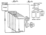
- the reel servo system will now be described in conjunction with two functional block diagrams shown in Figs. 4 and 5.
- the upper block diagram shown in Fig. 4 illustrates the reel servo system in its capstan engaged mode whereas the block diagram of Fig. 5 illustrates the reel servo in its capstan nonengaged mode.
- the capstan is engaged in the modes of record, normal play and variable speed reproducing, except still frame reproducing, and is not engaged in shuttle, cue and still frame reproducing.
- Figs. 4 and 5 While the block diagram of Figs. 4 and 5 are relatively self-explanatory, the components thereof include the microprocessor 30 which receives input information such as tachometer pulses from the take-up reel 60 via line 62, tachometer pulses from the supply reel 64 via line 66 and input information via line 68 relating to the position of a tensioning arm 70 around which tape 72 is wrapped.
- the tape from the supply reel passes over a guide 74 and the tensioning arm 70 about the helical wrap scanning drum (not shown), past the capstan 76 which engages the tape in cooperation with a pinch roller 78 on the opposite side of the tape.
- the tape is then wound around an idler 80, another guide 82 and onto the take-up reel 60.
- the microprocessor 30 receives the tachometer input information which enables it to compute the diameter of tape pack wrapped on the supply and take-up reels, and it also receives signals that indicate the position of the tension arm 70.
- the microprocessor provides output signals via line 84 to a digital-to-analog converter 86 which provides an analog signal which controls a motor drive amplifier 88 that in turn controls the supply reel drive motor.
- the microprocessor controls the take-up reel via output line 90, digital-to-analog converter 92, and motor drive amplifier 94 for driving the take-up reel motor. As is shown in Figs.
- the idler 80 has a tachometer which provides a tape tach signal on line 85 indicating the tape speed and is applied to the microprocessor 30.
- a potentiometer 87 (Fig. 5) that is controllable by an operator also provides an input signal to the microprocessor relating to the speed of the tape during shuttling which is controlled by an operator.
- the torque on the tape is controlled as a function of the size of the tape pack wrapped on the reel (the reel size) and it is controlled so that the capstan drive motor will perform a known and precise amount of work.
- the tension on the tape will be controlled so that the capstan drive motor is doing a precise amount of work. This will prevent the capstan drive motor from operating in a crossover area of the motor drive amplifier.
- the supply reel is controlled by a position servo loop having as its components the tension arm, the microprocessor, the digital-to-analog converter and the motor drive amplifier.
- the microprocessor During this mode, the microprocessor generates the error information, the reel tape pack diameter information, the reel speed information, the tape speed information and utilizes this information to provide the digital output signals to the digital-to-analog converter to properly control the motor drive amplifier.
- the microprocessor measures the tape pack diameter by calculating the same utilizing tachometer pulses from the reel tachometers together with tape speed information from the idler tachometer.
- the block diagram of Fig. 5 illustrates the manner in which the reel servo operates.
- the take up reel 60 is controlled in a velocity servo loop mode.
- the velocity servo loop uses the tape tachometer pulses from the idler tachometer which are indicative of the tape speed and compares them to a reference which is derived from an 8-bit number that is determined by the setting of the shuttle potentiometer control 87 in Fig. 5.
- the tape tachometer signal is applied to a comparator 96, the other input of which is supplied by the reference and provides a digital signal to the digital-to-analog converter 92 for controlling the motor drive amplifier 94 to operate the take up reel drive motor.
- the take up reel will supply tape 72 at the speed determined by the operator, such as 150 or 300 i.p.s., for example.
- the use of the velocity servo loop enables accurate control of the transport at low speeds, without the use of the capstan 76 which, as previously mentioned, is not engaged during shuttle, cueing and still frame reproducing.
- take up reel operation is controlled by a velocity servo loop and the supply reel operation is controlled by a position servo loop in the same manner as described with respect to Fig. 4.
- the tension arm reference is moved to the right which actually decreases the tension in the tape, such that the take up reel will pack or wind tape thereon with a nominal predetermined tension.
- the tension arm is moved to the left to increase the tape tension.
- This bias has the effect of overcoming friction of the transport and results in tape being wound onto the supply reel with a nominal predetermined tension. In this manner, the frictional load is maintained in the velocity loop and the supply reel is controlled as a function of the tension in the tension arm. It should be appreciated that while the dynamic characteristics in the forward direction are quite different from the dynamic characteristics in the reverse direction, the switching of the position loop tension arm reference from side to side causes the dynamic characteristics of forward and reverse to be comparable to one another.
- a potential problem is produced if the tape is moved in the reverse direction. This can be appreciated by the example of the take-up reel feeding tape into the tension arm and wherein a significant amount of friction is present so that the tape sticks in the transport and is not supplied to the tension arm. Stated in other words, if the take-up reel pushes tape toward the idler fast enough to put slack in the tape (sometimes referred to as "throwing a loop"), then it will lose contact with the idler and accurate cueing will not be possible, since the idler tachometer counter provides such information relating to tape movement.
- the tension arm 70 is repositioned to the left to increase the tension in the tape between the tension arm and the take-up reel 60 to thereby overcome the friction in the transport including friction caused by the scanner, the guides, the idler arm and the like.
- the microprocessor merely moves the tension arm to the left to increase the tension on the tape and after the tension arm is moved to its new position, then the take-up reel will begin to supply or push tape toward the idler and the increased tension caused by the tension arm will prevent any slack occurring in the tape path.
- the reel servo also has an acceleration loop control provided by the microprocessor to insure that during shuttle, the tape is not being moved too rapidly for either the take-up or supply reel.
- limits of tension arm movement are set (which are preferably different for each direction of tape movement) and as the tape is accelerated to its shuttle speed, any movement of the arm beyond one of the limits causes the take-up reel speed to be changed to return the arm to a position within the limits which returns the arm to the required tension.
- Another mode that is programmed into the reel servo is a threading mode which is carried out before any active operational mode is performed.
- the microprocessor essentially determines if the transport has been operated after it has been threaded. If a tape is placed on the apparatus and is not manipulated to remove the slack in it, then if it is placed into one of the active operating modes, it could be possible to snap the tape taut and stretch it, or violently move the tension arm or the like, which could damage the tape and/or the transport components.
- the threading mode is effective to slowly wind the supply and take-up reels relative to one another so as to bring the tape to a proper tension level and effectively slowly and carefully remove any slack in the tape and this is done by the microprocessor through programmed control.
- the program includes an instruction which asks if the tape had previously been threaded before an active operation is commenced and if it has not, then it slowly drives the reel motors to remove the slack in the tape by measuring the position of the tension arm and as the tape is brought to its proper tension level, the tension arm will be moved into a positional range that is appropriate for the particular operation that will be accomplished. When it reaches its nominal range, then the program control permits the active operation to commence.
- microprocessor circuitry The microprocessor circuitry
- Figs. 8a and 8b which together comprises a single schematic.
- the bulk of the circuitry of the apparatus described herein is contained on only two printed circuit boards and one of said printed circuit boards contains the microprocessor itself.
- the layout of the circuitry is such that address control of bidirectional buffers enable the data bus from the microprocessor to be connected to either the first or the second printed circuit board.
- the microprocessor 30, which is a Motorola integrated circuit Model MC 6802 has 16 address lines which address circuit components as well as specific addresses of memory circuits.
- address lines A o through A 15 extend rightwardly to a random access memory 280 which is controlled by address lines A o through A 7 , as well as respective programmable read only memories 282 and 284 (Fig. 8b) which are controlled by address lines A o through A11.
- the address lines also extend to a buffer 286 which has output lines indicated generally at 288 which extend to the second printed circuit board address lines.
- the lines 288 also extend downwardly to respective decoder integrated circuits 290 and 292 which are used to select ports P o through P is .
- the address lines also extend to yet another decoder 294 which provides selection of various programmable timer inegrated circuits T A through T H .
- Decoders 290, 292 and 294 are enabled when a master decode enable line S 4 is active and this is provided by a master decode circuit 296 located to the left of the decoder 294.
- address lines A 12 , A 13 and A 14 from the microprocessor 30 control the address selection master decode enable output lines So through S 7 that activate various portions of the circuitry.
- the decoded output line So enables the random access memory 280
- decode output S 6 enables the memory 282
- decode output S 7 similarly enables memory 284.
- the data bus 31 from the microprocessor comprises eight output lines Do through D 7 extending to the memories 280, 282, 284 as well as to bidirectional buffers 298 and 300.
- Buffer 290 has output lines that extend the data bus to the second printed circuit board, and it is activated by the decode output S 5 . Activation of the decode output S 4 enables the decoders 290, 292 and 294 as well as the other bidirectional buffer 300 which effectively extends the data bus to the remaining circuitry shown in the upper portion of Figs. 8a and 8b and to remaining circuitry on board No. 1.
- the data bus 31 has input latches 302 and 304 connected thereto and an output latch 306 being shown in Fig. 8b.
- the data lines 308 are also connected to these latches and the lines 208 represent a data bus to the machine control system which has a separate microprocessor controlled system for carrying out other machine control functions of the apparatus independently of the system controlled by microprocessor 30.
- the interaction of operator control and mode switches, diagnostics and the like with the servo system of the present invention is carried out through this data bus via the latches 302, 304 and 306.
- latches are respectively enabled by enable lines E o , E 1 and E 2 which are decoded outputs of a decoder circuit 310 that has operator activated address lines A o through A3 from the machine control system.
- the decode circuit 310 is enabled by a line 312 from the machine control system.
- a latch 314 that is connected to the data bus can receive a data word which decodes an address for controlling a multiplexing switch 316.
- the switch 316 selects one of the left inputs thereof for application onto line 318 that extends to an analog-to-digital converter, indicated generally at 320, having output lines 322 which extend to a latch 324 which applies data onto the data bus for use by the microprocessor when a port line P o is enabled from the address decoder 292.
- the multiplexing switch 316 can select a capstan servo control track error signal applied via line 326, an automatic scan tracking movable element position error signal applied via line 328 or a signal that is indicative of the position of the tension arm 70 applied via line 330.
- the circuitry at the upper portion of Fig. 8a provides an analog signal on line 330 that represents the position of the previously described arm through appropriate loop compensation circuitry indicated generally at 331.
- the arm positional reference for forward and reverse arm locations during shuttle and still frame reproducing is set by coding lines 333 and 335 by means of the output latch 314 from the microprocessor.
- line 337 can be selected to measure the actual mechanical arm position for tape threading and unthreading.
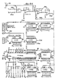
- the reel servo system that has been previously described with respect to the block diagrams of Figs. 4 and 5 is largely controlled by the microprocessor 30 together with the specific circuitry shown in Fig. 9 together with the timing diagrams of Figs. 6 and 7.
- the circuitry of Fig. 9 it is shown to be interconnected to the main data bus 31 via various lines and has inputs comprised of take-up reel tachometer information via lines 440 and 442, supply reel tachometer information via lines 444 and 446 as well as tape direction information from line 448 and tape tachometer information via line 450.
- the output signals from the microprocessor 30 are directed through the data bus 31 to digital-to-analog converters 452 and 454 which provide output drive signals to the take-up reel motor drive amplifier via line 456 and to the supply reel motor drive amplifier via line 458.
- the diameter of the tape packed on each reel is measured by the reel servo circuitry for the purpose of programming the torque that will be required on the reel during various operating modes. More specifically, by knowing the diameter of tape pack on the take-up reel 60 and supply reel 64, torque can be programmed so that the tension on the tape is maintained in a proper range during the various modes. It is desirable to maintain the appropriate torque so that tension is maintained at proper levels during operation.
- the reel tape pack diameter information is also useful in monitoring the operation of the system and if the measured reel diameter is greater than a maximum known actual value, then the microprocessor knows that something is wrong in the system. Moreover, as tape is being wound on or off one of the reels, it is known through the diameter values that it is approaching the end so that the microprocessor can slow down the reel speeds to prevent tape from flying off the reel.
- the reel servo system not only is capable of measuring the diameter of tape pack on both of the take-up and supply reels, it also instantaneously determines the direction that the reels are rotating.
- the servo system also has information relating to the tape speed and direction and uses the tape period information for use in the automatic scan tracking servo system, particularly to assist in determining whether a track jump is to occur at the next opportunity.
- a counter chip 460 is adapted to acquire information for determining the take-up reel tape pack diameter and a second integrated circuit counter chip 462 is adapted to supply comparable information for the supply reel. These circuits are identical and have 8-bit bidirectional data lines interconnected to the data bus 31 for communicating with the microprocessor.
- the counter chip 460 has two counters 464 and 466 which alternately accumulate a count of tachometer pulses from processed tape tachometer and a third counter 468 accumulates tape tachometer pulses directly from the idler 80 and therefore provide an indication of the tape speed.
- any one of the counters in the chip 460 circuit can be addressed through address lines A 1 and A 2 when enabled by the TF enable line, the microprocessor has access to the tape speed count from the counter 468 circuit and therefore the count is not needed for the same purpose in the other integrated circuit chip 462 which has comparable information relating to the supply reel.
- a counter 469 is used with the microprocessor 30 to determine supply reel speed during a tape threading operation.
- the counters 464 and 466 alternately accumulate a tape tachometer count which clocks the counters when they are enabled and they accumulate counts for a period corresponding to the reel tachometer period.
- the circuitry which controls the counters in Fig. 9 includes input take-up reel tachometer signals on lines 440 and 442 which are 90 degrees apart, with the inputs being applied to respective comparators 470 and 472 having respective output lines 474 and 476 which extend to respective multiply-by-two circuits 478 and 480, each of which is comprised of and EXCLUSIVE OR gate, an inverter and capacitor which operate to provide an output pulse at the EXCLUSIVE OR gate output for each edge or transition that is produced by the associated comparator.
- the output of the EXCLUSIVE OR for multiplier 478 triggers a D-latch 482 which has its Q output extending to the D input of another latch 484 which provides a direction value on line 486 that extends to a buffer 488 which provides a signal onto the data bus 31.
- the level of the line indicates the direction that the take-up reel is rotating.
- the output of the multiply-by-two 480 clocks another D-latch 490 which has its D input provided by line 474 and the Q output on line 492 and the Q output on line 494 of the second latch 490 provide signals for enabling either the counters 464 or 466.
- the Q output line 492 is also applied to an EXCLUSIVE OR gate 496 which has one input provided by the tape tachometer pulse signal on line 450.
- the output of the EXCLUSIVE OR 496 produces a clock signal on line 498 for clocking both counters and it clocks the enabled one at a rate corresponding to the rate of the tape tachometer signal.
- the use of the EXCLUSIVE OR gate 496 overcomes a problem that would arise as a result of the tape being stuck and the reels continuing to move. If the tape is stuck, there will not be a tape tachometer pulse received and then the counters 464 and 466 will not be accurate.
- the EXCLUSIVE OR gate 496 provides a clock edge that will validate the counters in the absence of a tape tachometer pulse.
- the reel tachometer will provide a single clock pulse to one of the counters that will result in the counter accumulating a count of one and this is detected by the microprocessor as being an invalid condition that indicates the reels are still turning while the tape is stopped. The microprocessor then shuts down the reel motors as is described.
- Fig. (1) represents an exaggerated illustration of the processed tape tachometer pulses that are received by the counters 464 and 466.
- Figs. 6(2) and 6(3) illustrate the input signals on lines 498 and 494 to the two counters 464 and 466, respectively, it being appreciated that the illustration of Fig. 6(2) is the inverse of Fig. 6(3).
- the counter receiving the positive-going edge will be reset and will begin accumulating count as shown in Figs. 6(4) and 6(5).
- Fig. 6(2) shows a varying duration period which is shown to be exaggerated to illustrate a pronounced change in the reel tape pack diameter. The longer the duration of a level, the larger the reel tape pack size and conversely, if a very narrow or short duration level occurs, it is an indication that the reel tape pack size is smaller and would therefore accumulate a lesser count in the active counter.
- the microprocessor 30 interrogates the counters 466 and 464, it will obtain a value from both counters and it is programmed to utilize the higher count of the two. Thus, if the interrogation occurs at the point in time P 1 , the counter 464 contains a higher count than counter 466 and the microprocessor will utilize the higher count of the counter 464 in performing its calculations. However, if the interrogation occurs at the point in time P 2 , then counter 466 will have a larger accumulated count and it will use this value. It should be appreciated that if the reel tap pack diameter is increasing, such as would be the case for the point P 2 , the most accurate value from counter 466 would indeed indicate that it is increasing and this information is virtually instantaneously available.
- the microprocessor has available to it the pertinent information relating to reel tape pack diameter at any particular time. It should be appreciated that the circuitry for the supply reel is identical to that of the take-up reel so that the diameter of the tape on the supply reel can also be calculated at any time.
- the diameter numbers that are obtained are integrated by the microprocessor to have a stable average value of the diameter of tape wrap.
- Fig. 9 also contains circuitry which measures the tape period, i.e., the inverse of the tape speed and the tape period information is used by the microprocessor primarily for predicting the ramp slope and whether a track jump operation should be accomplished at the appropriate time during each revolution of the transducing head.
- the tape period circuitry is primarily used for the automatic scan tracking system, but since it utilizes the tape tachometer information for providing dock time period it is conveniently located in the area of the circuitry which contains the reel servo circuitry.
- the circuitry includes a counter integrated circuit chip 500 which includes two programmable counters 502 and 504 which alternately accumulate a 2H rate count via line 524 during a period of tape movement that is a function of the tape tachometer pulses on line 450.
- a tape tachometer signal on input line 450 is applied to the clock input of a counter 506 which is programmed to act as a divider and which divides the tachometer rate for a NTSC signal by five which output signal appears on line 508 that extends to a NAND gate 510 and to an inverter 512, the output of the inverter of which clocks a D flip-flop 514 configured as a divide-by-two having Q and Q outputs which are applied to the inputs of the counters 502 and 504 by respective lines 516 and 518.
- the NAND gate 510 controls a D-latch 520 and sets the same so that its Q output enables an AND gate 522 which has its other input the clock signal on line 524 which is at a 2H rate which clocks the counters through respective AND gates 526 and 528.
- the 2H clock pulses clock the appropriately enabled counter 502 or 504.
- the 2H clock is shown to be exaggerated to illustrate fewer than actual number of pulses than occur.
- the waveform of Fig. 7(3) is the complement of that shown in Fig. 7(2). If the tape is moving rapidly, then the period of the signals in Figs. 7(2) and 7(3) will be shorter than when the tape is moving more slowly. Thus, the waveforms shown in Figs. 7(2) and 7(3) are exaggerated to illustrate varying rates of speed of the tape for purposes of illustration. The occurrence of a positive-going edge in either of the waveforms of Figs.
- the microprocessor when the microprocessor interrogates the counters 502 and 504 to determine the tape period, it will take the larger of the two counts as the accurate value.
- the benefit of having both counters available for the microprocessor is that they provide accurate and instantaneous information relating to the tape period. By using two counters, the larger count will be reasonably accurate and the value is immediately available for use by the microprocessor during operation.
- the microprocessor knows when the tape has in fact stopped. The count increases as the tape slows and if the tape is stopped, then the count will eventually reach the terminal count of the counter and will roll over and begin anew. Since this would provide a count that would be incorrect, provision is made for preventing this from occurring and this is accomplished by a gate 530 having input lines provided by the output of counters 502 and 504. When either of the counters reaches terminal count, it will provide an output signal on one input of the gate 530 which in turn will provide a low output on line 532 that extends to the clock input of the D flip-flop 520 via inverter 534.
- the clocking of the D flip-flop 520 causes its Q output to go low and disable gate 522 which blocks the 2H frequency clock so that the counters 502 and 504 will no longer count. Since this occurs at the terminal count of the counters, the microprocessor knows by virtue of a terminal count being received upon interrogation, that in fact the tape has stopped. Once the tape moves again so that a tape tachometer pulse occurs, the signal will be applied through counter 506 to one input of gate 510 which will set the flip-flop 520 causing its Q output to go low and enable gate 522 to resume clocking of the counters 502 or 504.
Landscapes
- Engineering & Computer Science (AREA)
- Computer Hardware Design (AREA)
- Control Of Multiple Motors (AREA)
Description
- The present invention generally relates to servo systems for recording and reproducing apparatus and, more particularly, to a microprocessor controlled reel servo for a magnetic tape recording and reproducing apparatus.
- It is readily appreciated that video recording and reproducing apparatus, particularly, apparatus that records and reproduces video information of broadcast quality, is highly technical and complex equipment that requires sophisticated electronic as well as mechanical components and systems. For broadcast quality recording and reproducing apparatus, particularly video tape recording and reproducing apparatus, the level of technical sophistication is extraordinary in terms of the amount of control that is required to reliably operate the apparatus at broadcast quality standards. Such videotape recording apparatus have a number of servo systems which control their operation, including a servo system which controls the reel drive motors which drive the supply and take-up reels.
- While the improved reel servo of the present invention is only one of the major servos of a recording and/or reproducing apparatus that are controlled by a single microprocessor, the reel servo of the present invention contains many desirable functional features that are found in prior art reel servos, including microprocessor controlled reel servo systems. There is little doubt that the use of a single microprocessor for controlling all of the major servos in the apparatus results in significant improvements in terms of the inherent communication between the various servos. The interaction of one servo with another in a more intimate manner also provides improved functional capabilities that are very difficult to implement using hardwired logic and other circuitry.
- It is known from IBE International Broadcast Engineer,
Volume 12, No. 176 March 1981 pages 18-26 to provide a video tape recording and playback machine with a tape reel servo such that some of the operating modes of the machine can be performed without using the tape-driving capstan. It is known from DE-A-2511263 to provide, in an audio tape recorder, signal processing and logic circuitry for receiving output signals from velocity sensors, associated with the motors for each of the take-up and supply reels and with an idler roller, and to determine the diameter of tape packs on the reels in response to those output signals. - According to one aspect of the invention there is provided a servo control system for a video recording and reproducing machine having a supply reel and a take-up reel for the transport of magnetic tape past a scanner, the control system comprising velocity sensors associated with each reel to provide respective pulses denoting the rotational velocity of the respective reel and a velocity sensor to provide independently of the capstan pulses denoting the longitudinal velocity of the tape, processing means for measuring the diameter of a tape pack on one of the reels and means for controlling the speed of the said one reel in response to the measured diameter of the tape pack, the processing means comprising two counters, the counters being arranged when activated to accumulate the pulses indicative of the longitudinal tape speed and being alternately cleared and activated in response to the rotational velocity denoting pulses from the respective one of the above mentioned reel velocity sensors, the clearing and activating of one counter interrupting the accumulation of pulses by the other counter, and the processing means being arranged to interrogate both counters and to use the larger accumulated count to determine the tape pack diameter.
- According to another aspect of the invention there is provided apparatus for determining the rotational speed of a reel relative to the longitudinal speed of a tape wrapped on the reel, comprising: means for generating clock pulses having a frequency indicative of the longitudinal speed of the tape, means for generating control pulses having a frequency related to the rotational speed of the reel and processing means including a counter which counts the clock pulses and is cleared and activated by a control pulse, characterised in that the processing means comprises two counters which are alternately cleared and activated by the control pulses, the clearing and activation of either counter inhibiting counting of the clock pulses by the other counter and means for interrogating both counters and selecting the larger accumulated count.
- According to a further aspect of the invention a method of determining the diameter of a tape pack on a reel which supplies or takes up take comprises generating clock pulses at a frequency representing the longitudinal speed of the tape; generating control pulses at a frequency representing the rotational velocity of the reel, and in response to the occurrence of a control pulse clearing a counter and causing the counter to count clock pulses, characterised by clearing and activating a second counter alternately with the first mentioned counter, inhibiting one counter from counting when the other is cleared and activated, and interrogating both counters to ascertain the larger of the two counts accumulated by the counters.
- One object of the present invention is to provide an improved reel servo of the foregoing type which utilizes longitudinal tape speed information together with reel tachometer information to instantaneously determine the diameter of tape wrapped on each of the reels. An associated object is to provide the diameter information in a novel way whereby it is instantaneously available to the microprocessor for control of the reel servo as well as other servos.
-
- Figure 1 is a functional block diagram illustrating the functional interaction of the microprocessor with the various servo systems of the apparatus, and of the microprocessor and other important circuitry;
- Fig. 2 is another functional block diagram of the microprocessor and illustrates the manner in which it receives input information relation to the operation of the apparatus and provides output signals that are used to control the operation of the apparatus;
- Figs. 3a and 3b are very broad flow charts illustrating the software functional operation of the microprocessor;
- Fig. 4 is a functional block diagram of the reel servo system during operation in the record, play and variable speed reproduce modes wherein the capstan is engaged;
- Fig. 5 is a functional block diagram of the reel servo system as operated in the shuttle mode, during cueing and during still frame reproducing mode wherein the capstan is not engaged;
- Figs. 6 and 7 are timing diagrams that are useful in illustrating the operation of the reel servo system;
- Figs. 8a and 8b together comprise a detailed electrical schematic diagram illustrating the microprocessor together with machine control interfacing circuitry and multiplexing analog-to-digital converting circuitry; and
- Fig. 9 is a detailed electrical schematic diagram of the reel servo circuitry of the present invention, which reel servo circuitry carries out the operation of the functional block diagrams shown in Figs. 4 and 5.
- Broadly stated, the reel servo system of the present invention is controlled by a microprocessor which also controls the other major servo systems of a tape recording and reproducing apparatus, the other servos of which include: 1) a scanning drum servo which rotates the transducing head at the proper speed during operations; 2) a capstan servo which controls the movement of the tape during recording and during most, but not all reproducing operations; and, 3) the automatic scan tracking servo which controls the transverse movement relative to the longitudinal direction of the track of the reproduced head to have it accurately follow a track during reproducing and particularly during reproducing for special motion effects wherein the tape is being transported at a speed other than normal playback speed. The microprocessor receives digital information as well as digitally converted analog information from various locations throughout the circuitry and apparatus, processes such information and thereafter provides digital output signals to other circuitry, some signals of which are converted into the analog domain for controlling the various operations that are performed by the apparatus in its various modes. The nature of the operation of the other servos and the circuitry that carries out the operation thereof will not be specifically described herein, but such servos are comprehensively described in European Patent Application No. 83301016.8 entitled "Microprocessor Controlled Multiple Servo System for a Recording and/or Rerroducing Apparatus", filed on even date herewith.
- Turning initially to the block diagram of Fig. 1, there is shown a
microprocessor 30 which is interconnected by adata bus 31 with areel servo 32, acapstan servo 34, ascanner servo 36 and amachine communication interface 38 which essentially controls the various modes of the recording and reproducing apparatus as manipulated by an operator or from a remote location. The microprocessor also interacts with areference generator 40 which receives as an input thereto a reference station composite sync signal vialine 42 and the reference generator generates system clocks which clock the microprocessor and which in turn synchronizes all of the clock timing of the servos and other circuitry. The microprocessor also interacts with the automaticscan tracking servo 44 and a tape sync processor 46 which has a tape composite sync signal input vialine 48. The tape sync processor additionally provides a signal to the timebase corrector interface 50 which provides appropriate timing and control signals for use by the time base corrector to provide a broadcast quality video image having the requisite stability and vertical position with respect to system reference as well as the correct chroma information, which processing varies depending upon what reproducing mode the apparatus is being operated. - While the functional block diagrams shown in Fig. 1 illustrate the interaction of the microprocessor with the various servo systems of the apparatus, with machine control and with the time base corrector and the like, the system can also be functionally described in terms of input and output signals that are provided to and from the microprocessor and this functional block diagram is shown in Fig. 2. The
microprocessor 30 receives frequency, phase and timing data shown by the upper left functional block including such input signals as scanner tach pulses, reel tack pulses, capstan tach pulses, reference vertical and frame timing signals, which is converted into digital information for processing by the microprocessor. The microprocessor also receives analog information shown by the block left of the microprocessor which is converted into digital information for processing by the microprocessor and such analog input signals include the automatic scan tracking error signals, the tension arm error signals and various motor current signals from the reel drive motors, the capstan drive motor and the scanner drive motor. The data bus also receives operating mode information as well as other machine control data and it processes this information and provides status information and other data. The microprocessor generates digital information which is converted to analog information and these analog output signals include control signals for the capstan servo, the reel servo, the scanner servo and the automatic scan tracking servo. Similarly the microprocessor provides frequency, phase and timing output information which include delay signals, phase and timing output information that are used by the various servos and other circuits. - The microprocessor controlled system of the present embodiment has a unique advantage in that it is adaptable for recording and reproducing video signals from any standard worldwide format, i.e., it can record and reproduce a NTSC signal having 525 lines or a PAL or SECAM signal having 625 horizontal lines. The input control line can be set to operate either as a 525 or 625 line system and the various constants and other software values which control the servos and other circuitry of the apparatus will be selected for proper operation. Similarly, another control line can be set for either a PAL or SECAM format system once a 625 line system is specified. The software in memory includes instructions and numerical constants that will permit the apparatus to properly operate regardless of the television signal format that is being used.
- In accordance with an aspect of the present apparatus, the microprocessor controlled servo system described herein is adapted to control the reel servo system and the scanner servo system during the high speed shuttle mode in a way so as to protect the recording and reproducing heads, while the tape is being wound off one of the reels onto the other. In the past, as the tape was nearing the end so as to be wound on a single reel during high speed shuttle, the potential for chipping the ceramic recording and reproducing head was quite high. In accordance with an aspect of the apparatus described herein, during high speed shuttle, reel tape pack diameter information that is determined by the microprocessor is used to control the reel servo and the scanning drum servo to perform a sequence of events which substantially reduce if not eliminate the possibility of heads being chipped. When the microprocessor determines that the tape has almost reached the end of being wound off of one reel, it controls the reel servo to stop the tape and it also reverses scanner motor current to brake the scanner. After the tape has been stopped, the reel servo moves the tape at a relatively slow rate, e.g., twice normal recording speed, and the scanning drum is allowed to coast while the tape is wound entirely off of one reel on to the other.
- The apparatus is programmed to operate in various operating modes as is shown in the broad flow chart of Fig. 3a. The flow chart representing microprocessor software shows that once the machine is initialized, a mode is selected and these modes include stop, record, slow and fast motion reproduce, stop motion or still frame reproduce, ready and normal play. Once the apparatus is placed in an operating mode, then it undergoes a mode test to determine if it is a valid mode and if such is the case, it will return to that mode and begin running the program that controls the apparatus in that mode. If the mode test is invalid, then it will return to the stop mode and the apparatus will stop. After the apparatus is placed in a valid mode, it will continue in that mode until some event occurs, such as a mode change or a completion of some operation. Included as part of each operating mode are various subroutines which are called as shown in Fig. 3a. Certain ones of these subroutines are used in various ones of the operating modes. For example, the play mode will contain a block of code instructions that will call up various subroutines in the specified order. As long as the apparatus is operating in the play mode it will repetitively go through this block of code instructions. When the scanner tachometer pulse occurs, it will cause an interrupt to the microprocessor as shown in Fig. 3b.
- The microprocessor operates on an interrupt basis, with an interrupt resulting from onee of three inputs. The software determines which input caused the interrupt and the microprocessor then enters the appropriate block of code which runs through various subroutines until it reaches the end and then returns to the instruction that had previously been completed prior to the interrupt. The scanner tachometer pulse originally triggered a counter which has a count that exceeds the maximum time required to store all current relevant information in stack registers in the microprocessor. When this is done, it is ready to immediately perform the instructions in the
scanner 1 block of code. This is carried out by the scanner interrupt block of code which causes the microprocessor to store the information and then literally wait for thescanner 1 interrupt. After thescanner 1 block of code is run, the microprocessor removes the information from the stack registers and resumes running through the instructions specified by the operating mode. - In accordance with an important aspect of the present embodiment, the reel servo system will now be described in conjunction with two functional block diagrams shown in Figs. 4 and 5. The upper block diagram shown in Fig. 4 illustrates the reel servo system in its capstan engaged mode whereas the block diagram of Fig. 5 illustrates the reel servo in its capstan nonengaged mode. The capstan is engaged in the modes of record, normal play and variable speed reproducing, except still frame reproducing, and is not engaged in shuttle, cue and still frame reproducing.
- While the block diagram of Figs. 4 and 5 are relatively self-explanatory, the components thereof include the
microprocessor 30 which receives input information such as tachometer pulses from the take-up reel 60 vialine 62, tachometer pulses from thesupply reel 64 vialine 66 and input information vialine 68 relating to the position of atensioning arm 70 around whichtape 72 is wrapped. Thus, the tape from the supply reel passes over aguide 74 and thetensioning arm 70 about the helical wrap scanning drum (not shown), past the capstan 76 which engages the tape in cooperation with apinch roller 78 on the opposite side of the tape. The tape is then wound around an idler 80, anotherguide 82 and onto the take-up reel 60. Themicroprocessor 30 receives the tachometer input information which enables it to compute the diameter of tape pack wrapped on the supply and take-up reels, and it also receives signals that indicate the position of thetension arm 70. The microprocessor provides output signals vialine 84 to a digital-to-analog converter 86 which provides an analog signal which controls amotor drive amplifier 88 that in turn controls the supply reel drive motor. In a similar manner, the microprocessor controls the take-up reel viaoutput line 90, digital-to-analog converter 92, andmotor drive amplifier 94 for driving the take-up reel motor. As is shown in Figs. 4 and 5, the idler 80 has a tachometer which provides a tape tach signal online 85 indicating the tape speed and is applied to themicroprocessor 30. A potentiometer 87 (Fig. 5) that is controllable by an operator also provides an input signal to the microprocessor relating to the speed of the tape during shuttling which is controlled by an operator. - When the reel servo is in a capstan engaged mode as shown in Fig. 4, and the take-
up reel 60 is receiving tape, the torque on the tape is controlled as a function of the size of the tape pack wrapped on the reel (the reel size) and it is controlled so that the capstan drive motor will perform a known and precise amount of work. In other words, when it is operating in the capstan engaged mode, the tension on the tape will be controlled so that the capstan drive motor is doing a precise amount of work. This will prevent the capstan drive motor from operating in a crossover area of the motor drive amplifier. In this mode, the supply reel is controlled by a position servo loop having as its components the tension arm, the microprocessor, the digital-to-analog converter and the motor drive amplifier. During this mode, the microprocessor generates the error information, the reel tape pack diameter information, the reel speed information, the tape speed information and utilizes this information to provide the digital output signals to the digital-to-analog converter to properly control the motor drive amplifier. The microprocessor measures the tape pack diameter by calculating the same utilizing tachometer pulses from the reel tachometers together with tape speed information from the idler tachometer. - When the reel servo is operating in the capstan nonengaged modes during forward or reverse shuttle as well as cue and in the still frame reproducing mode, the block diagram of Fig. 5 illustrates the manner in which the reel servo operates. When the reel servo is operating in the forward or reverse shuttle or cue modes, the take up
reel 60 is controlled in a velocity servo loop mode. The velocity servo loop uses the tape tachometer pulses from the idler tachometer which are indicative of the tape speed and compares them to a reference which is derived from an 8-bit number that is determined by the setting of theshuttle potentiometer control 87 in Fig. 5. - As shown therein, the tape tachometer signal is applied to a
comparator 96, the other input of which is supplied by the reference and provides a digital signal to the digital-to-analog converter 92 for controlling themotor drive amplifier 94 to operate the take up reel drive motor. In this manner, the take up reel will supplytape 72 at the speed determined by the operator, such as 150 or 300 i.p.s., for example. - The use of the velocity servo loop enables accurate control of the transport at low speeds, without the use of the capstan 76 which, as previously mentioned, is not engaged during shuttle, cueing and still frame reproducing. When the tape is being shuttled in either direction, take up reel operation is controlled by a velocity servo loop and the supply reel operation is controlled by a position servo loop in the same manner as described with respect to Fig. 4. When the tape is being shuttled in the forward direction, the tension arm reference is moved to the right which actually decreases the tension in the tape, such that the take up reel will pack or wind tape thereon with a nominal predetermined tension. When the tape is being shuttled in the reverse direction, the tension arm is moved to the left to increase the tape tension. This bias has the effect of overcoming friction of the transport and results in tape being wound onto the supply reel with a nominal predetermined tension. In this manner, the frictional load is maintained in the velocity loop and the supply reel is controlled as a function of the tension in the tension arm. It should be appreciated that while the dynamic characteristics in the forward direction are quite different from the dynamic characteristics in the reverse direction, the switching of the position loop tension arm reference from side to side causes the dynamic characteristics of forward and reverse to be comparable to one another.
- A potential problem is produced if the tape is moved in the reverse direction. This can be appreciated by the example of the take-up reel feeding tape into the tension arm and wherein a significant amount of friction is present so that the tape sticks in the transport and is not supplied to the tension arm. Stated in other words, if the take-up reel pushes tape toward the idler fast enough to put slack in the tape (sometimes referred to as "throwing a loop"), then it will lose contact with the idler and accurate cueing will not be possible, since the idler tachometer counter provides such information relating to tape movement.
- To overcome the potential problem of throwing a loop in the tape which would detrimentally affect the cueing operation due to loss of contact by the idler 80 and therefore the tape tachometer counter, the
tension arm 70 is repositioned to the left to increase the tension in the tape between the tension arm and the take-up reel 60 to thereby overcome the friction in the transport including friction caused by the scanner, the guides, the idler arm and the like. To increase the tension, the microprocessor merely moves the tension arm to the left to increase the tension on the tape and after the tension arm is moved to its new position, then the take-up reel will begin to supply or push tape toward the idler and the increased tension caused by the tension arm will prevent any slack occurring in the tape path. - The reel servo also has an acceleration loop control provided by the microprocessor to insure that during shuttle, the tape is not being moved too rapidly for either the take-up or supply reel. Thus, after the tension arm is appropriately located to provide the proper tape tension for packing the tape onto one of the reels as previously described, limits of tension arm movement are set (which are preferably different for each direction of tape movement) and as the tape is accelerated to its shuttle speed, any movement of the arm beyond one of the limits causes the take-up reel speed to be changed to return the arm to a position within the limits which returns the arm to the required tension.
- Another mode that is programmed into the reel servo is a threading mode which is carried out before any active operational mode is performed. The microprocessor essentially determines if the transport has been operated after it has been threaded. If a tape is placed on the apparatus and is not manipulated to remove the slack in it, then if it is placed into one of the active operating modes, it could be possible to snap the tape taut and stretch it, or violently move the tension arm or the like, which could damage the tape and/or the transport components. Thus, the threading mode is effective to slowly wind the supply and take-up reels relative to one another so as to bring the tape to a proper tension level and effectively slowly and carefully remove any slack in the tape and this is done by the microprocessor through programmed control. Essentially, the program includes an instruction which asks if the tape had previously been threaded before an active operation is commenced and if it has not, then it slowly drives the reel motors to remove the slack in the tape by measuring the position of the tension arm and as the tape is brought to its proper tension level, the tension arm will be moved into a positional range that is appropriate for the particular operation that will be accomplished. When it reaches its nominal range, then the program control permits the active operation to commence.
- Before describing the detailed electrical circuit schematic diagrams of the various servos that have been previously described with respect to functional block diagrams, the schematic diagrams which contain the
microprocessor 30 itself will be briefly described in connection with Figs. 8a and 8b which together comprises a single schematic. As previously mentioned, and as has been shown by the block diagram of Fig. 1, the bulk of the circuitry of the apparatus described herein is contained on only two printed circuit boards and one of said printed circuit boards contains the microprocessor itself. The layout of the circuitry is such that address control of bidirectional buffers enable the data bus from the microprocessor to be connected to either the first or the second printed circuit board. As shown in Fig. 8a, themicroprocessor 30, which is a Motorola integratedcircuit Model MC 6802 has 16 address lines which address circuit components as well as specific addresses of memory circuits. As shown on the lower portion of themicroprocessor 30 in Fig. 8a, address lines Ao through A15 extend rightwardly to arandom access memory 280 which is controlled by address lines Ao through A7, as well as respective programmable read onlymemories 282 and 284 (Fig. 8b) which are controlled by address lines Ao through A11. The address lines also extend to abuffer 286 which has output lines indicated generally at 288 which extend to the second printed circuit board address lines. Thelines 288 also extend downwardly to respective decoder integratedcircuits decoder 294 which provides selection of various programmable timer inegrated circuits TA through TH. -
Decoders master decode circuit 296 located to the left of thedecoder 294. As is clearly illustrated, address lines A12, A13 and A14 from themicroprocessor 30 control the address selection master decode enable output lines So through S7 that activate various portions of the circuitry. For example, when active, the decoded output line So enables therandom access memory 280, decode output S6 enables thememory 282 and decode output S7 similarly enablesmemory 284. Thedata bus 31 from the microprocessor comprises eight output lines Do through D7 extending to thememories bidirectional buffers Buffer 290 has output lines that extend the data bus to the second printed circuit board, and it is activated by the decode output S5. Activation of the decode output S4 enables thedecoders bidirectional buffer 300 which effectively extends the data bus to the remaining circuitry shown in the upper portion of Figs. 8a and 8b and to remaining circuitry on board No. 1. - As shown in Fig. 8a, the
data bus 31 has input latches 302 and 304 connected thereto and an output latch 306 being shown in Fig. 8b. The data lines 308 are also connected to these latches and the lines 208 represent a data bus to the machine control system which has a separate microprocessor controlled system for carrying out other machine control functions of the apparatus independently of the system controlled bymicroprocessor 30. The interaction of operator control and mode switches, diagnostics and the like with the servo system of the present invention is carried out through this data bus via thelatches 302, 304 and 306. These latches are respectively enabled by enable lines Eo, E1 and E2 which are decoded outputs of adecoder circuit 310 that has operator activated address lines Ao through A3 from the machine control system. Thedecode circuit 310 is enabled by a line 312 from the machine control system. By selectively enabling decode output lines Eo, E1 and E2, data can be input into thelatches 302 and 304 for communication onto the data bus of themicroprocessor 30 and enabling the latch 306 permits data from themicroprocessor 30 to be latched therein for communication to the machine control system vialines 308. - The remaining portion of the circuitry shown in the upper portion of Figs. 8a and 8b concern the analog information input that is provided to the
microprocessor 30. When port P1 fromdecoder 292 is active, alatch 314 that is connected to the data bus can receive a data word which decodes an address for controlling amultiplexing switch 316. Theswitch 316 selects one of the left inputs thereof for application ontoline 318 that extends to an analog-to-digital converter, indicated generally at 320, havingoutput lines 322 which extend to alatch 324 which applies data onto the data bus for use by the microprocessor when a port line Po is enabled from theaddress decoder 292. - The
multiplexing switch 316 can select a capstan servo control track error signal applied vialine 326, an automatic scan tracking movable element position error signal applied vialine 328 or a signal that is indicative of the position of thetension arm 70 applied vialine 330. The circuitry at the upper portion of Fig. 8a provides an analog signal online 330 that represents the position of the previously described arm through appropriate loop compensation circuitry indicated generally at 331. The arm positional reference for forward and reverse arm locations during shuttle and still frame reproducing is set by codinglines output latch 314 from the microprocessor. In addition, line 337 can be selected to measure the actual mechanical arm position for tape threading and unthreading. - The reel servo system that has been previously described with respect to the block diagrams of Figs. 4 and 5 is largely controlled by the
microprocessor 30 together with the specific circuitry shown in Fig. 9 together with the timing diagrams of Figs. 6 and 7. Turning to the circuitry of Fig. 9, it is shown to be interconnected to themain data bus 31 via various lines and has inputs comprised of take-up reel tachometer information via lines 440 and 442, supply reel tachometer information via lines 444 and 446 as well as tape direction information from line 448 and tape tachometer information vialine 450. The output signals from themicroprocessor 30 are directed through thedata bus 31 to digital-to-analog converters 452 and 454 which provide output drive signals to the take-up reel motor drive amplifier vialine 456 and to the supply reel motor drive amplifier vialine 458. As previously mentioned, the diameter of the tape packed on each reel is measured by the reel servo circuitry for the purpose of programming the torque that will be required on the reel during various operating modes. More specifically, by knowing the diameter of tape pack on the take-up reel 60 andsupply reel 64, torque can be programmed so that the tension on the tape is maintained in a proper range during the various modes. It is desirable to maintain the appropriate torque so that tension is maintained at proper levels during operation. The reel tape pack diameter information is also useful in monitoring the operation of the system and if the measured reel diameter is greater than a maximum known actual value, then the microprocessor knows that something is wrong in the system. Moreover, as tape is being wound on or off one of the reels, it is known through the diameter values that it is approaching the end so that the microprocessor can slow down the reel speeds to prevent tape from flying off the reel. - The reel servo system not only is capable of measuring the diameter of tape pack on both of the take-up and supply reels, it also instantaneously determines the direction that the reels are rotating. The servo system also has information relating to the tape speed and direction and uses the tape period information for use in the automatic scan tracking servo system, particularly to assist in determining whether a track jump is to occur at the next opportunity.
- Returning to the aspect of determining the tape pack diameter on the take-up and supply reels, a
counter chip 460 is adapted to acquire information for determining the take-up reel tape pack diameter and a second integratedcircuit counter chip 462 is adapted to supply comparable information for the supply reel. These circuits are identical and have 8-bit bidirectional data lines interconnected to thedata bus 31 for communicating with the microprocessor. Thecounter chip 460 has twocounters third counter 468 accumulates tape tachometer pulses directly from the idler 80 and therefore provide an indication of the tape speed. Since any one of the counters in thechip 460 circuit can be addressed through address lines A1 and A2 when enabled by the TF enable line, the microprocessor has access to the tape speed count from thecounter 468 circuit and therefore the count is not needed for the same purpose in the otherintegrated circuit chip 462 which has comparable information relating to the supply reel. However, acounter 469 is used with themicroprocessor 30 to determine supply reel speed during a tape threading operation. Thecounters counters - The circuitry which controls the counters in Fig. 9 includes input take-up reel tachometer signals on lines 440 and 442 which are 90 degrees apart, with the inputs being applied to
respective comparators respective output lines circuits 478 and 480, each of which is comprised of and EXCLUSIVE OR gate, an inverter and capacitor which operate to provide an output pulse at the EXCLUSIVE OR gate output for each edge or transition that is produced by the associated comparator. The output of the EXCLUSIVE OR formultiplier 478 triggers a D-latch 482 which has its Q output extending to the D input of anotherlatch 484 which provides a direction value on line 486 that extends to abuffer 488 which provides a signal onto thedata bus 31. The level of the line indicates the direction that the take-up reel is rotating. The output of the multiply-by-two 480 clocks another D-latch 490 which has its D input provided byline 474 and the Q output online 492 and the Q output online 494 of thesecond latch 490 provide signals for enabling either thecounters Q output line 492 is also applied to an EXCLUSIVE ORgate 496 which has one input provided by the tape tachometer pulse signal online 450. The output of the EXCLUSIVE OR 496 produces a clock signal online 498 for clocking both counters and it clocks the enabled one at a rate corresponding to the rate of the tape tachometer signal. The use of theEXCLUSIVE OR gate 496 overcomes a problem that would arise as a result of the tape being stuck and the reels continuing to move. If the tape is stuck, there will not be a tape tachometer pulse received and then thecounters gate 496 provides a clock edge that will validate the counters in the absence of a tape tachometer pulse. The reel tachometer will provide a single clock pulse to one of the counters that will result in the counter accumulating a count of one and this is detected by the microprocessor as being an invalid condition that indicates the reels are still turning while the tape is stopped. The microprocessor then shuts down the reel motors as is described. - The operation of the above circuitry can be more clearly understood by referring to Fig. 6. Fig. (1) represents an exaggerated illustration of the processed tape tachometer pulses that are received by the
counters lines counters input lines 498und 494, the counter receiving the positive-going edge will be reset and will begin accumulating count as shown in Figs. 6(4) and 6(5). When a subsequent positive-going transition on the other counter input occurs, the first counter is stopped and the second counter will be cleared and begin accumulating count. The illustration of Fig. 6(2) shows a varying duration period which is shown to be exaggerated to illustrate a pronounced change in the reel tape pack diameter. The longer the duration of a level, the larger the reel tape pack size and conversely, if a very narrow or short duration level occurs, it is an indication that the reel tape pack size is smaller and would therefore accumulate a lesser count in the active counter. - If the
microprocessor 30 interrogates thecounters counter 464 contains a higher count thancounter 466 and the microprocessor will utilize the higher count of thecounter 464 in performing its calculations. However, if the interrogation occurs at the point in time P2, then counter 466 will have a larger accumulated count and it will use this value. It should be appreciated that if the reel tap pack diameter is increasing, such as would be the case for the point P2, the most accurate value fromcounter 466 would indeed indicate that it is increasing and this information is virtually instantaneously available. Conversely, if the reel tape pack diameter is decreasing, as would occur at point in time P3, the counters would be enabled and zeroed more rapidly so that the value at P3 would be available very quickly, as shown in Figs. 6(2) and 6(3). Therefore, by using the higher valued counter of the two counters, the microprocessor has available to it the pertinent information relating to reel tape pack diameter at any particular time. It should be appreciated that the circuitry for the supply reel is identical to that of the take-up reel so that the diameter of the tape on the supply reel can also be calculated at any time. - The diameter numbers that are obtained are integrated by the microprocessor to have a stable average value of the diameter of tape wrap.
- In accordance with another important aspect the reel servo, Fig. 9 also contains circuitry which measures the tape period, i.e., the inverse of the tape speed and the tape period information is used by the microprocessor primarily for predicting the ramp slope and whether a track jump operation should be accomplished at the appropriate time during each revolution of the transducing head. For this reason, the tape period circuitry is primarily used for the automatic scan tracking system, but since it utilizes the tape tachometer information for providing dock time period it is conveniently located in the area of the circuitry which contains the reel servo circuitry.
- The value of the tape period is determined in a manner very similar to that described with respect to the take-up reel tape pack diameter measurement and in this regard, the circuitry includes a counter integrated
circuit chip 500 which includes twoprogrammable counters line 524 during a period of tape movement that is a function of the tape tachometer pulses online 450. Thus, a tape tachometer signal oninput line 450 is applied to the clock input of acounter 506 which is programmed to act as a divider and which divides the tachometer rate for a NTSC signal by five which output signal appears online 508 that extends to a NAND gate 510 and to aninverter 512, the output of the inverter of which clocks a D flip-flop 514 configured as a divide-by-two having Q and Q outputs which are applied to the inputs of thecounters respective lines latch 520 and sets the same so that its Q output enables an ANDgate 522 which has its other input the clock signal online 524 which is at a 2H rate which clocks the counters through respective ANDgates 526 and 528. - During operation, the 2H clock pulses clock the appropriately enabled counter 502 or 504. Referring to Fig. 7(1), the 2H clock is shown to be exaggerated to illustrate fewer than actual number of pulses than occur. The waveform of Fig. 7(3) is the complement of that shown in Fig. 7(2). If the tape is moving rapidly, then the period of the signals in Figs. 7(2) and 7(3) will be shorter than when the tape is moving more slowly. Thus, the waveforms shown in Figs. 7(2) and 7(3) are exaggerated to illustrate varying rates of speed of the tape for purposes of illustration. The occurrence of a positive-going edge in either of the waveforms of Figs. 7(2) or 7(3) will cause the appropriate counter to be reset and begin counting the number of 2H clock pulses that occur until the other counter receives an enabling positive-going edge. This causes the other counter to be reset and begin counting, and simultaneously stops the count of the previously counting counter. As is illustrated from Figs. 7(4) and 7(5), when the tape is moving more slowly, the active counter will accumulate a larger count than when the tape is moving more rapidly.
- As was the case with respect to the take-up and supply reel counters, when the microprocessor interrogates the
counters - It is also essential that the microprocessor knows when the tape has in fact stopped. The count increases as the tape slows and if the tape is stopped, then the count will eventually reach the terminal count of the counter and will roll over and begin anew. Since this would provide a count that would be incorrect, provision is made for preventing this from occurring and this is accomplished by a
gate 530 having input lines provided by the output ofcounters gate 530 which in turn will provide a low output online 532 that extends to the clock input of the D flip-flop 520 viainverter 534. The clocking of the D flip-flop 520 causes its Q output to go low and disablegate 522 which blocks the 2H frequency clock so that thecounters counter 506 to one input of gate 510 which will set the flip-flop 520 causing its Q output to go low and enablegate 522 to resume clocking of thecounters - From the foregoing detailed description it should be appreciated that an improved reel servo has been shown and described which has may desirable functional capabilities that are not found in prior art apparatus. Since the present invention is microprocessor controlled, the take-up and supply reels can be operated under different types of closed servo loop control during different operating modes, which greatly improves its overall operation. More specifically, it enables shuttling, cueing and still frame reproduction to be performed without the use of a capstan, which permits a less sophisticated and expensive capstan assembly to be used than would otherwise be possible. The unique use of circuitry enables the diameter of the tape wrapped on each of the supply and take-up reels to be instantaneously available for use by the microprocessor in controlling not only the reel servo, but other servos during particular operation during particular modes.
Claims (7)
Applications Claiming Priority (2)
| Application Number | Priority Date | Filing Date | Title |
|---|---|---|---|
| US36465282A | 1982-04-02 | 1982-04-02 | |
| US364652 | 1982-04-02 |
Related Child Applications (1)
| Application Number | Title | Priority Date | Filing Date |
|---|---|---|---|
| EP86201834.8 Division-Into | 1983-02-25 |
Publications (2)
| Publication Number | Publication Date |
|---|---|
| EP0091186A1 EP0091186A1 (en) | 1983-10-12 |
| EP0091186B1 true EP0091186B1 (en) | 1989-02-15 |
Family
ID=23435472
Family Applications (2)
| Application Number | Title | Priority Date | Filing Date |
|---|---|---|---|
| EP83301014A Expired EP0091186B1 (en) | 1982-04-02 | 1983-02-25 | An improved reel servo system in a recording and/or reproducing apparatus |
| EP19860201834 Expired EP0236588B1 (en) | 1982-04-02 | 1983-02-25 | Reel servo system in a recording and/or reproducing apparatus |
Family Applications After (1)
| Application Number | Title | Priority Date | Filing Date |
|---|---|---|---|
| EP19860201834 Expired EP0236588B1 (en) | 1982-04-02 | 1983-02-25 | Reel servo system in a recording and/or reproducing apparatus |
Country Status (3)
| Country | Link |
|---|---|
| EP (2) | EP0091186B1 (en) |
| JP (2) | JPS58218062A (en) |
| DE (2) | DE3379208D1 (en) |
Families Citing this family (12)
| Publication number | Priority date | Publication date | Assignee | Title |
|---|---|---|---|---|
| JPS6051986A (en) * | 1983-08-31 | 1985-03-23 | Fanuc Ltd | Tape reader fitted with reel |
| JPS6122461A (en) * | 1984-07-05 | 1986-01-31 | Fujitsu Ltd | Magnetic tape device |
| JPH0630192B2 (en) * | 1985-03-28 | 1994-04-20 | ソニー株式会社 | Tracking control signal generation circuit for recording / reproducing apparatus |
| EP0198658A3 (en) * | 1985-04-12 | 1989-01-25 | Ampex Corporation | Apparatus and method for remotely controlling the displacement of a movable web |
| US4633333A (en) * | 1985-06-24 | 1986-12-30 | International Business Machines Corporation | Detection of instantaneous speed variations in a tape drive |
| JPH01298560A (en) * | 1988-05-26 | 1989-12-01 | Sony Corp | Reel motor controller |
| JP2600857B2 (en) * | 1988-10-22 | 1997-04-16 | ソニー株式会社 | Magnetic tape transfer device |
| JPH03154257A (en) * | 1989-11-10 | 1991-07-02 | Matsushita Electric Ind Co Ltd | magnetic recording and playback device |
| JP2940171B2 (en) * | 1991-01-30 | 1999-08-25 | ソニー株式会社 | Servo controller for tape recording / reproducing device |
| DE4129593A1 (en) * | 1991-09-06 | 1993-03-11 | Broadcast Television Syst | METHOD FOR CONTROLLING AND REGULATING A MAGNETIC TAPE DEVICE |
| DE19633149A1 (en) * | 1996-08-17 | 1998-02-19 | Philips Patentverwaltung | Servo control system |
| US10089443B2 (en) | 2012-05-15 | 2018-10-02 | Baxter International Inc. | Home medical device systems and methods for therapy prescription and tracking, servicing and inventory |
Family Cites Families (14)
| Publication number | Priority date | Publication date | Assignee | Title |
|---|---|---|---|---|
| US3725655A (en) * | 1971-06-24 | 1973-04-03 | Ibm | Media transport performance measurements |
| AU497538B2 (en) * | 1974-03-14 | 1978-12-14 | Rca Corporation | Controlling tension of magnetic tape |
| GB1500094A (en) * | 1976-04-07 | 1978-02-08 | Burroughs Corp | Apparatus and method for controlling a tape drive to maintain a substantially constant linear tape velocity |
| US4097005A (en) * | 1976-05-03 | 1978-06-27 | Ampex Corporation | Web transport system |
| BE855968A (en) * | 1976-07-05 | 1977-10-17 | Staar Sa | METHOD AND DEVICE FOR MONITORING AND COMMANDING THE TRANSFER OF MATERIAL FROM A DEBITRING COIL TO A RECEIVING COIL |
| JPS5389712A (en) * | 1977-01-19 | 1978-08-07 | Nec Corp | Magnetic tape device |
| GB1602446A (en) * | 1977-04-18 | 1981-11-11 | Sangamo Weston | Tape position detection in tape recorders |
| JPS5522859A (en) * | 1978-08-07 | 1980-02-18 | Sato Heizaburou | Method of connecting lead member for porcelain electric part |
| AT365363B (en) * | 1979-09-20 | 1982-01-11 | Philips Nv | RECORDING AND / OR PLAYING DEVICE |
| JPS5922300B2 (en) * | 1979-12-25 | 1984-05-25 | アンペックス・コ−ポレ−ション | Tape speed control method |
| JPS56127954A (en) * | 1980-03-07 | 1981-10-07 | Teac Co | Tape recorder |
| JPS56127957A (en) * | 1980-03-07 | 1981-10-07 | Matsushita Electric Ind Co Ltd | Tape take-up device |
| JPS56153552A (en) * | 1980-04-30 | 1981-11-27 | Sony Corp | Tape tension control mechanism in magnetic recorder and reproducer |
| JPS5718044A (en) * | 1980-07-07 | 1982-01-29 | Olympus Optical Co Ltd | Tension servo-device |
-
1983
- 1983-02-25 DE DE8383301014T patent/DE3379208D1/en not_active Expired
- 1983-02-25 DE DE8686201834T patent/DE3382456D1/en not_active Expired - Lifetime
- 1983-02-25 EP EP83301014A patent/EP0091186B1/en not_active Expired
- 1983-02-25 EP EP19860201834 patent/EP0236588B1/en not_active Expired
- 1983-03-17 JP JP58045253A patent/JPS58218062A/en active Granted
-
1990
- 1990-09-18 JP JP2248596A patent/JPH03209657A/en active Pending
Non-Patent Citations (1)
| Title |
|---|
| IBE INTERNATIONAL BROADCAST ENGINEER, vol. 12, no. 176, March 1981, pages 18-26, Eton, Berks., GB, L.V. HEDLUND: "The TR-800 VTR- a computer-based total system design" * |
Also Published As
| Publication number | Publication date |
|---|---|
| EP0236588B1 (en) | 1991-11-06 |
| DE3379208D1 (en) | 1989-03-23 |
| DE3382456D1 (en) | 1991-12-12 |
| EP0236588A3 (en) | 1987-09-23 |
| EP0236588A2 (en) | 1987-09-16 |
| JPH0516093B2 (en) | 1993-03-03 |
| JPS58218062A (en) | 1983-12-19 |
| JPH03209657A (en) | 1991-09-12 |
| EP0091186A1 (en) | 1983-10-12 |
Similar Documents
| Publication | Publication Date | Title |
|---|---|---|
| US4536806A (en) | Microprocessor controlled multiple servo system for a recording and/or reproducing apparatus | |
| EP0197782B1 (en) | Apparatus for reproducing digital signals | |
| EP0236588B1 (en) | Reel servo system in a recording and/or reproducing apparatus | |
| US4649441A (en) | Head reel servo system in a recording and/or reproducing apparatus | |
| US4635138A (en) | Microprocessor controlled reproducing apparatus having asynchronous reproducing capability | |
| US4544967A (en) | Automatic scan tracking servo system | |
| US4514671A (en) | Head scanning servo system in a recording and/or reproducing apparatus | |
| EP0430043A2 (en) | Digital signal processing circuit | |
| JPH0534741B2 (en) | ||
| EP0091187B1 (en) | Microprocessor controlled reproducing apparatus having asynchronous reproducing capability | |
| EP0227052B1 (en) | Servo control apparatus | |
| KR100248926B1 (en) | Servo control device for video apparatus | |
| EP0091190B1 (en) | A programmable nonlinear speed control for a recording and/or reproducing apparatus | |
| US4538190A (en) | Programmable non-linear speed control for a recording and/or reproducing apparatus | |
| US5805371A (en) | Monitoring tape position in a magnetic recording/reproducing apparatus | |
| JP2774540B2 (en) | Tape running device | |
| JPH05290448A (en) | Recording and reproducing device | |
| JP2575102B2 (en) | Rotating head playback device | |
| JPS6117553Y2 (en) | ||
| JPS6236764A (en) | magnetic recording and reproducing device | |
| JP2629350B2 (en) | Magnetic recording / reproducing device | |
| US20010016110A1 (en) | Search mode for a D-VHS recorder | |
| JP2701253B2 (en) | Tape-shaped recording medium playback device | |
| JPH0294189A (en) | High-speed searching method of rotary head type digital recording and reproducing device | |
| JPS61273787A (en) | Monitoring method for movement extent of tape |
Legal Events
| Date | Code | Title | Description |
|---|---|---|---|
| PUAI | Public reference made under article 153(3) epc to a published international application that has entered the european phase |
Free format text: ORIGINAL CODE: 0009012 |
|
| AK | Designated contracting states |
Designated state(s): CH DE FR GB LI NL |
|
| 17P | Request for examination filed |
Effective date: 19840314 |
|
| GRAA | (expected) grant |
Free format text: ORIGINAL CODE: 0009210 |
|
| AK | Designated contracting states |
Kind code of ref document: B1 Designated state(s): CH DE FR GB LI NL |
|
| REF | Corresponds to: |
Ref document number: 3379208 Country of ref document: DE Date of ref document: 19890323 |
|
| ET | Fr: translation filed | ||
| PLBE | No opposition filed within time limit |
Free format text: ORIGINAL CODE: 0009261 |
|
| STAA | Information on the status of an ep patent application or granted ep patent |
Free format text: STATUS: NO OPPOSITION FILED WITHIN TIME LIMIT |
|
| 26N | No opposition filed | ||
| REG | Reference to a national code |
Ref country code: GB Ref legal event code: 732E |
|
| PGFP | Annual fee paid to national office [announced via postgrant information from national office to epo] |
Ref country code: CH Payment date: 19940224 Year of fee payment: 12 |
|
| PGFP | Annual fee paid to national office [announced via postgrant information from national office to epo] |
Ref country code: NL Payment date: 19940228 Year of fee payment: 12 |
|
| NLS | Nl: assignments of ep-patents |
Owner name: AMPEX SYSTEMS CORPORATION TE REDWOOD CITY, CALIFOR |
|
| PG25 | Lapsed in a contracting state [announced via postgrant information from national office to epo] |
Ref country code: LI Effective date: 19950228 Ref country code: CH Effective date: 19950228 |
|
| PG25 | Lapsed in a contracting state [announced via postgrant information from national office to epo] |
Ref country code: NL Effective date: 19950901 |
|
| NLV4 | Nl: lapsed or anulled due to non-payment of the annual fee |
Effective date: 19950901 |
|
| REG | Reference to a national code |
Ref country code: GB Ref legal event code: 732E |
|
| PGFP | Annual fee paid to national office [announced via postgrant information from national office to epo] |
Ref country code: FR Payment date: 20010213 Year of fee payment: 19 |
|
| PGFP | Annual fee paid to national office [announced via postgrant information from national office to epo] |
Ref country code: GB Payment date: 20010221 Year of fee payment: 19 Ref country code: DE Payment date: 20010221 Year of fee payment: 19 |
|
| REG | Reference to a national code |
Ref country code: GB Ref legal event code: IF02 |
|
| PG25 | Lapsed in a contracting state [announced via postgrant information from national office to epo] |
Ref country code: GB Free format text: LAPSE BECAUSE OF NON-PAYMENT OF DUE FEES Effective date: 20020225 |
|
| PG25 | Lapsed in a contracting state [announced via postgrant information from national office to epo] |
Ref country code: DE Free format text: LAPSE BECAUSE OF NON-PAYMENT OF DUE FEES Effective date: 20020903 |
|
| GBPC | Gb: european patent ceased through non-payment of renewal fee |
Effective date: 20020225 |
|
| PG25 | Lapsed in a contracting state [announced via postgrant information from national office to epo] |
Ref country code: FR Free format text: LAPSE BECAUSE OF NON-PAYMENT OF DUE FEES Effective date: 20021031 |
|
| REG | Reference to a national code |
Ref country code: FR Ref legal event code: ST |