EP0091084A1 - Sewing machine controlling apparatus - Google Patents
Sewing machine controlling apparatus Download PDFInfo
- Publication number
- EP0091084A1 EP0091084A1 EP83103140A EP83103140A EP0091084A1 EP 0091084 A1 EP0091084 A1 EP 0091084A1 EP 83103140 A EP83103140 A EP 83103140A EP 83103140 A EP83103140 A EP 83103140A EP 0091084 A1 EP0091084 A1 EP 0091084A1
- Authority
- EP
- European Patent Office
- Prior art keywords
- speed
- signal
- set position
- machine
- sewing machine
- Prior art date
- Legal status (The legal status is an assumption and is not a legal conclusion. Google has not performed a legal analysis and makes no representation as to the accuracy of the status listed.)
- Granted
Links
Images


Classifications
-
- H—ELECTRICITY
- H02—GENERATION; CONVERSION OR DISTRIBUTION OF ELECTRIC POWER
- H02P—CONTROL OR REGULATION OF ELECTRIC MOTORS, ELECTRIC GENERATORS OR DYNAMO-ELECTRIC CONVERTERS; CONTROLLING TRANSFORMERS, REACTORS OR CHOKE COILS
- H02P29/00—Arrangements for regulating or controlling electric motors, appropriate for both AC and DC motors
- H02P29/0016—Control of angular speed of one shaft without controlling the prime mover
-
- D—TEXTILES; PAPER
- D05—SEWING; EMBROIDERING; TUFTING
- D05B—SEWING
- D05B69/00—Driving-gear; Control devices
- D05B69/14—Devices for changing speed or for reversing direction of rotation
- D05B69/18—Devices for changing speed or for reversing direction of rotation electric, e.g. foot pedals
Definitions
- the present invention relates to a sewing machine controlling apparatus, which starts, stops a sewing machine or controls the variable speed in accordance with the position of an adjusting means for setting a sewing machine speed.
- the digital system which is common among the various systems, has a fatal disadvantage in that a boundary exists where the signal changes without fail, changes are caused between two adjacent signal values due to the variations of the sewing machine, when the pedal has been positioned on the condition of the boundary, to considerably vary the speed of the sewing machine, thus making it impossible to be put into practical use.
- an object of the present invention is to provide an improved sewing-machine controlling apparatus in which the speed setting can be smoothly switched in accordance with the position of the adjusting means, thus ensuring the stable speed operation, which is independent of the sewing-machine vibrations.
- a sewing machine controlling apparatus comprising an adjusting means for setting machine speed, a set position detecting means for converting the position of the adjusting means into a set position signal P D which is a digital value, a speed converting means for converting said set position signal into a speed setting signal S, a motor, which is step by step controlled in variable speed in accordance with said speed setting signal S, a machine to be driven by the motor, a controlling means for controlling the machine, a timer which can perform its presetting operation, wherein the shifting conditions from a speed setting signal S 1 in accordance with an optional set position signal P D1 to a speed setting signal S 2 in accordance with an optional set position signal P D2 are restricted only to a case where said set position signal P D2 has been maintained during a time T present into said timer.
- a pedal-position detecting circuit 1 which is connected with a microcomputer 3 through an A/D transducer 2.
- the circuit 1 converts the stepping amount from the reference position of a treadle pedal la provided in association with a sewing machine 8 into electric signals. For example, the reciprocating operation of the pedal is converted into a revolving action.
- a magnet is disposed at the central portion of the pedal for operative cooperation, and a means is used of detecting the rotary angle of the magnet with a magnetic reluctance element to amplify it.
- the output signal P A is outputted from the circuit 1 as an analog signal.
- the A/D transducer 2 is adapted to convert, into the digital signal P D of 4 bits, the analog signal P A of the circuit 1 to input into the microcomputer 3.
- the microcomputer 3 is connected with the sewing machine 8 through a pair of drivers 4, 5 and coils 6, 7, to constitute a means for controlling the sewing machine 8 in a central portion of the machine control.
- the drivers receive the outputs from the microcomputer 3 to drive the clutch coil 6 and the brake coil 7.
- a motor M is provided in association with the sewing machine 8 as a so-called electromagnetic coupling construction wherein the motor transmits the turning effort of a motor main-body, which is always rotating at a high speed, to an output shaft through the magnetic circuit due to the excitation of the clutch coil 6, the motor changes the sliding speed with respect to the rotary portion of the motor main-body by the intensity of the exciting current thereby to perform the speed controlling operation, and the motor is adapted to stop the output shaft through the magnetic circuit due to the excitation of the brake coil 7.
- the sewing machine E is normally coupled to the output shaft of the motor through a pulley, a belt.
- a needle position detecting circuit 9 is provided between the microcomputer 3 and the sewing machine 8, and is adapted to adjust a magnet piece, engaged with the shaft end of the sewing machine 8, in accordance with the needle-above position to rotate it in synchronous relation. to the rotation of the machine shaft.
- the needle-above position is detected, by a hall IC. which is provided in association with the circuit 9 and is disposed in a stationary position opposite to the magnet piece, to output a needle-above signal NU.
- a frequency generator 10 is connected between the microcomputer 3 and the sewing machine 8 together with a wave-form shaping circuit 11 and is normally engaged with the machine shaft end to output signals, which have a period to be varied in accordance with the revolution speed of the sewing machine.
- the wave-form shaping circuit 11 is composed of a circuit with a comparator as a center for shaping the signals to be outputted from the frequency generator into rectangular-wave pulse signals FG.
- the pulse signals FG of the circuit 11 are inputted into the offering terminal iNT of the microcomputer 3.
- the motion amount is detected by the pedal-position detecting circuit 1 thereby to output an analog signal P A .
- the analog signal P A is converted into a set position signal P D , which is a digital value of 4 bits, by an A/D transducer 2.
- the microcomputer 3 converts the set position signal P D , if the value of the set position signal P D is a normal value or more, into numerical value, i.e., speed setting signals S, showing the frequency-division number of the pulse signal FG by a ROM table to be described later, has it therein as a frequency-division number value to set it in a RAM (RAM1), outputs a signal CL, excites a clutch coil 6 through the driver 4 thereby to drive the sewing machine 8.
- RAM random access memory
- the microcomputer 3 divides in frequency the offering input by the number stored in the above-described RAM1, measures the frequency-divided period, effects an assignment operation in an operation formula to be described later to control the exciting time of the clutch brake of the section of the following pulse signal FG.
- the speed controlling operation for the sewing machine 8 is performed while the measurement and controlling within the microcomputer 3 are being repeated. Accordingly, the sewing machine 8 is operated at a speed in accordance with the analog signal P A outputted through the detection by the pedal-position detecting circuit 1.
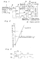
- Fig. 2 and Fig. 3 which are charts showing the principles of controlling the speed, will be described hereinafter with reference to the drawings.
- the measured period Tp after the frequency division, of the pulse signal FG is first measured and is substituted into the operation formula.
- the clutch coil if the operation results are positive, or the brake coil, if they are negative, is controllingly excited for a period after the frequency division of the following pulse signal FG only for the time of the operation results. Namely, when the measured period Tp has been varied in a smaller direction, i.e., when the sewing machine has been varied onto a high-speed side, the on-duty of the clutch is reduced. As the case may be (T P2 or lower is provided), the brake is thrown and operates to prevent the speed from being higher.
- the on-duty of the clutch is increased.
- the controlling operation is performed to prevent the speed from becoming lower.
- a safety operation is effected at a point a (measured period T P1 , clutch-on time T C1 ) just matched to the machine load in this manner.
- Fig. 3 the stable operating condition at a low speed N P is shown.
- a safe operation is effected at such a duty as the clutch coil exciting signal CL may be outputted by T C1 to the period T P1 of the pulse signal FG.
- the measured period T P rapidly increases and accordingly the engagement ratio of the clutch increases to accelerate the sewing machine.
- the machine load torque in the increased speed remains almost unchanged, and the last clutch on-duty becomes the same as during the operation of the low speed N P .
- the operation is effected at an approximate of a point a. Namely, assume that the time of the frequency dividing operation is 1, and the operation is adapted to be effected at a speed twice as fast as the low speed N P .
- the speed setting signal (0) of the * mark in the table I shown above is required only during the shifting time from the driving operation to the stop.
- the 0, 1, 2 of the setting position signals P D corresponding to the * mark are distinguished as the stop instruction regions by a special program.
- the one stage portion of the reference speed Np suddenly changes at the machine speed in particularly 3 or higher region, i.e. driving instruction region, of the set position signal P D , for example, in the boundary between 5 and 6, or 7 and 8. If the pedal is positioned to become the boundary, considerably large speed variation of the reference speed N P is caused by the vibration of the machine or the slight change in the power-supply voltage.
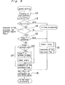
- the embodiment wherein measures are taken against the speed variation by the use of a timer, which is one of the characteristics of the present invention will be shown in the flow chart of Fig. 5.
- the set position signal P D1 is newly read at the 12, the check is made as to whether it stays within the stop instruction range of 0 through 2 at the 13, and it goes to a stop processing routine when it stays within the stop instruction range. If it does not stay within the stop instruction range, the driving condition of the machine continues. Then, at the 14, it is compared with a set position signal P D2 previously read. If it is not an adjacent value or when time passes by "T” if it is an adjacent value, the timer stops at the 15 and the set position signal P Dl newly read is adopted. If this is not the case, a time "T" is preset to the timer at the 17 to start the timer thereby to adopt the set position signal P D2 . After the above-described timer has been started, it is preset by a special timer-interrupt processing routine (not shown). When it has been started, it is always clocking.
- the processing shown in the flow chart is inserted into one portion of the control processing loop during the machine driving operation. Accordingly, when the set position signal P D1 newly read is a value adjacent to the conventional set position signal P D2 , the condition is not rendered effective until the condition continues time T or more. On the other cases, the processing content of ready effective is shown.
- the reply to the motion to the respective adjacent pedal positions is delayed when two long time is set. It is considered to be easy to set a time T which is not subject to the influences caused by vibration in the normal machine operation or by changes in the instantaneous analog signal P A through the power-supply variation, and is independent of the reply delay. Also, in the normal sewing operation, it is ordinary that the operation wherein the value of the set position signal P D considerably changes is effected, especially in the sewing operation demanding the response property.
- the time T is neglected in such a case as described hereinabove and the ready answer can be given. It is considered that the time T can be set to a sufficiently long time.
- the above-description is given about a case where the pedal is used as an adjusting means for setting the machine speed.
- the present invention is effective even where a variable volume for restricting the highest speed of the machine is used as the adjusting means, and the set position signal is provided through the A/D conversion, or where the set position signal is adapted to be made directly by a code switch.
- the ROM table for conversion to the speed setting S (frequency-division number value) from the set position signal P D is in two types as shown in Table II and Table III.
- the relationship of the machine speed with respect to the set position signal P will be described as graph in Fig. 6. Referring to Fig. 6, the solid line is shown in accordance with the R O M table 1, while the broken line is shown in accordance with the R O M table 2.
- R O M tables 1 and 2 Two types of R O M tables 1 and 2 are different only in portion marked with , i.e., portion where the speed setting signal S is switched.
- the speed setting speed signal (0) of the mark in the same table is necessary only at the motion from the driving condition to the stop.
- the 0 through 5 of the set position signal P D corresponding to the mark is'distinguished as a stop instruction region in accordance with a special program.
- the set position signal P D1 is newly read, the check is made as to whether the P D1 stays within the stop instruction range at the 20, it goes to a stop processing routine if it stays within the range, the driving condition of the machine will continue if it does not stay within the stop instruction range. Then, at the 21, the check is made as to whether or not the set position ** signal PD1 newly read is equal to a value shown with mark in Table II and Table III. If so, the check is made as to whether or not the value is smaller by 1 than the P D2 previously read at the 22. If so, it is converted to the speed setting signal S by the R O M2 at the 23.
- the processing shown in the flow chart of Fig.7 is inserted into one portion of the control processing loop during the machine driving operation.
- the R O M table 2 is adopted, only when the set position signal P D1 newly read is next smaller by 1 than the conventional set position signal P D2 and is in the switching ** portion (the value of the mark of Table 1, Table 2) of the speed signal, to provide the broken line of the machine speed of Fig. 6.
- the ROM table 1 is adapted to provide the solid line machine speed of Fig. 6.
- ** the set position signal portion, shown with the mark, or the switching portion of the machine speed effects its hysteresis operation. Accordingly, when the range of the ** analog signal P A corresponding to the value of the mark is kept sufficiently large, the machine speed can be independent of the vibrations of the machine.
- the above-description is given about a case wherein the pedal is used as the adjusting means for setting the machine speed.
- the present invention is effective when the variable volume for restricting the maximum speed of the machine is used as the adjusting means, and the set position signal is provided through the A/D conversion, or even when the set position signal is adapted to be provided directly by a cord switch .
- the present invention provides a sewing machine controlling apparatus, which is independent, in machine speed, of the influence ⁇ , which are caused by changes in the pedal position signal P A through the vibrations of the machine or the variations in the power-supply voltage.
- the smooth speed switching operation which is free from the speed variation, can be realized even in the stepped switching point of the machine speed, thus resulting in greater advantages.
Landscapes
- Engineering & Computer Science (AREA)
- Mechanical Engineering (AREA)
- Textile Engineering (AREA)
- Power Engineering (AREA)
- Sewing Machines And Sewing (AREA)
Abstract
Description
- The present invention relates to a sewing machine controlling apparatus, which starts, stops a sewing machine or controls the variable speed in accordance with the position of an adjusting means for setting a sewing machine speed.
- Conventionally a system was mainly adopted of converting the position of the adjusting means as the sewing machine controlling apparatus into analog signals to make the analog signals speed setting signals, and composing the speed controlling portion of analog operation around an 5P amplitude circuit.
- However, in recent years the development in digital IC, etc. with microcomputers as central components is conspicuous. The speed controls are gradually digitized in terms of cost or reliability. Thus, the detection signals of the adjusting means are naturally required to be digitized. When the pedal of the sewing machine is used as the adjusting means, the various systems of interlocking a cord switch with several bits of switch being incorporated therein with the pedal as the digitizing means, disposing a screening plate, which is interlocked with the pedal and drilled to change the combined signals of the several bits, among several bits of light-emitting, light-receiving elements, interlocking a magnet with the pedal to detect the space change or the magnetic-flux direction change with hall elements or magnetic reluctance elements, furthermore converting the analog signals into digital signals thereby to provide the digital signals.
- 'However, the digital system, which is common among the various systems, has a fatal disadvantage in that a boundary exists where the signal changes without fail, changes are caused between two adjacent signal values due to the variations of the sewing machine, when the pedal has been positioned on the condition of the boundary, to considerably vary the speed of the sewing machine, thus making it impossible to be put into practical use.
- Accordingly, an object of the present invention is to provide an improved sewing-machine controlling apparatus in which the speed setting can be smoothly switched in accordance with the position of the adjusting means, thus ensuring the stable speed operation, which is independent of the sewing-machine vibrations.
- According to the present invention, there provides a sewing machine controlling apparatus, comprising an adjusting means for setting machine speed, a set position detecting means for converting the position of the adjusting means into a set position signal P D which is a digital value, a speed converting means for converting said set position signal into a speed setting signal S, a motor, which is step by step controlled in variable speed in accordance with said speed setting signal S, a machine to be driven by the motor, a controlling means for controlling the machine, a timer which can perform its presetting operation, wherein the shifting conditions from a speed setting signal S1 in accordance with an optional set position signal PD1 to a speed setting signal S2 in accordance with an optional set position signal PD2 are restricted only to a case where said set position signal PD2 has been maintained during a time T present into said timer.
- The object and other objects, features, aspects and advantages of the present invention become more apparent from the following detailed description of the present invention when taken in conjunction with the accompanying drawings.
-
- Fig. 1 is a block diagram of a sewing machine controlling apparatus according to the present invention,
- Fig. 2 is a chart for illustrating the principle of speed control for the sewing machine,
- Fig. 3 is a time chart showing the low-speed operating condition,
- Fig. 4 is a chart for illustrating the sewing machine speed with respect to the pedal position,
- Fig. 5 is a flow chart showing the speed sewing of the present invention,
- Fig. 6 is a chart for illustrating the sewing machine speed with respect to the pedal position in the other embodiment of the present invention, and
- Fig. 7 is a flow chart showing the same-speed setting.
- 'Referring to Fig. 1, there provides a pedal-
position detecting circuit 1 which is connected with amicrocomputer 3 through an A/D transducer 2. - The
circuit 1 converts the stepping amount from the reference position of a treadle pedal la provided in association with asewing machine 8 into electric signals. For example, the reciprocating operation of the pedal is converted into a revolving action. A magnet is disposed at the central portion of the pedal for operative cooperation, and a means is used of detecting the rotary angle of the magnet with a magnetic reluctance element to amplify it. Thus, the output signal PA is outputted from thecircuit 1 as an analog signal.. The A/D transducer 2 is adapted to convert, into the digital signal PD of 4 bits, the analog signal PA of thecircuit 1 to input into themicrocomputer 3. Themicrocomputer 3 is connected with thesewing machine 8 through a pair ofdrivers coils sewing machine 8 in a central portion of the machine control. The drivers receive the outputs from themicrocomputer 3 to drive theclutch coil 6 and thebrake coil 7. A motor M is provided in association with thesewing machine 8 as a so-called electromagnetic coupling construction wherein the motor transmits the turning effort of a motor main-body, which is always rotating at a high speed, to an output shaft through the magnetic circuit due to the excitation of theclutch coil 6, the motor changes the sliding speed with respect to the rotary portion of the motor main-body by the intensity of the exciting current thereby to perform the speed controlling operation, and the motor is adapted to stop the output shaft through the magnetic circuit due to the excitation of thebrake coil 7. The sewing machine E is normally coupled to the output shaft of the motor through a pulley, a belt. A needleposition detecting circuit 9 is provided between themicrocomputer 3 and thesewing machine 8, and is adapted to adjust a magnet piece, engaged with the shaft end of thesewing machine 8, in accordance with the needle-above position to rotate it in synchronous relation. to the rotation of the machine shaft. The needle-above position is detected, by a hall IC. which is provided in association with thecircuit 9 and is disposed in a stationary position opposite to the magnet piece, to output a needle-above signal NU. Afrequency generator 10 is connected between themicrocomputer 3 and thesewing machine 8 together with a wave-form shaping circuit 11 and is normally engaged with the machine shaft end to output signals, which have a period to be varied in accordance with the revolution speed of the sewing machine. The wave-form shaping circuit 11 is composed of a circuit with a comparator as a center for shaping the signals to be outputted from the frequency generator into rectangular-wave pulse signals FG. The pulse signals FG of thecircuit 11 are inputted into the offering terminal iNT of themicrocomputer 3. - The operation of the above-described apparatus will be described hereinafter.
- Once the pedal is stepped on by the operator from the reference position, the motion amount is detected by the pedal-
position detecting circuit 1 thereby to output an analog signal PA. The analog signal PA is converted into a set position signal PD, which is a digital value of 4 bits, by an A/D transducer 2. - The
microcomputer 3 converts the set position signal PD, if the value of the set position signal PD is a normal value or more, into numerical value, i.e., speed setting signals S, showing the frequency-division number of the pulse signal FG by a ROM table to be described later, has it therein as a frequency-division number value to set it in a RAM (RAM1), outputs a signal CL, excites aclutch coil 6 through thedriver 4 thereby to drive thesewing machine 8. - Accelerate the
sewing machine 8 as described hereinabove and the pulse signals FG are adapted to be outputted into the offering input terminal iNT of themicrocompute 3 through thefrequency generator 10 and the wave-form shaping circuit 11. Themicrocomputer 3 divides in frequency the offering input by the number stored in the above-described RAM1, measures the frequency-divided period, effects an assignment operation in an operation formula to be described later to control the exciting time of the clutch brake of the section of the following pulse signal FG. The speed controlling operation for thesewing machine 8 is performed while the measurement and controlling within themicrocomputer 3 are being repeated. Accordingly, thesewing machine 8 is operated at a speed in accordance with the analog signal PA outputted through the detection by the pedal-position detecting circuit 1. - Then, when the pedal is returned towards the reference position and the set position signal PD becomes smaller than the normal value, a low speed is set and the
brake coil 7 is excited through thedriver 5 so that thesewing machine 8 is rapidly reduced in speed to the low speed. When thesewing machine 8 becomes slower in speed, theclutch coil 6 is .turned off at a time point, when the need-above signal Nu from the needle-position detecting circuit 9 has been outputted, to excite thebrake coil 7 for a given time, so that it is caused to come into a stop in the needle-above position. - Thus, a series of operations of finishing a needlework, replacing it by the new needlework, and starting to sew it are adapted to be effected. The first embodiment of the present invention will be described in detail hereinafter with reference to the drawings of Fig. 2 and subsequent.
- Fig. 2 and Fig. 3, which are charts showing the principles of controlling the speed, will be described hereinafter with reference to the drawings.
- The operation formula of TCB=ATp-B as shown in Fig. 2 uses a straight-line system for simplification of the operation, in which the A is a constant corresponding to the gain of a normal system and the B is a constant, which can make fine adjustment of the speed, the A and B being determined, taking the safety, respondence of the system into consideration.
- Referring to Fig. 2, the measured period Tp, after the frequency division, of the pulse signal FG is first measured and is substituted into the operation formula. The clutch coil, if the operation results are positive, or the brake coil, if they are negative, is controllingly excited for a period after the frequency division of the following pulse signal FG only for the time of the operation results. Namely, when the measured period Tp has been varied in a smaller direction, i.e., when the sewing machine has been varied onto a high-speed side, the on-duty of the clutch is reduced. As the case may be (TP2 or lower is provided), the brake is thrown and operates to prevent the speed from being higher. When the measured period Tp has been varied in a bigger direction, i.e., when the sewing machine has been varied onto a low-speed side, the on-duty of the clutch is increased. The controlling operation is performed to prevent the speed from becoming lower. A safety operation is effected at a point a (measured period TP1, clutch-on time TC1) just matched to the machine load in this manner.
- The above-described condition is shown in Fig. 3. Referring to Fig. 3, the stable operating condition at a low speed NP is shown. A safe operation is effected at such a duty as the clutch coil exciting signal CL may be outputted by TC1 to the period TP1 of the pulse signal FG.
- When the pulse signal FG has been divided in frequency within the
microcomputer 3 as described hereinabove, the measured period TP rapidly increases and accordingly the engagement ratio of the clutch increases to accelerate the sewing machine. Assume that the machine load torque in the increased speed remains almost unchanged, and the last clutch on-duty becomes the same as during the operation of the low speed NP. The operation is effected at an approximate of a point a. Namely, assume that the time of the frequency dividing operation is 1, and the operation is adapted to be effected at a speed twice as fast as the low speed NP. - The construction example of the ROM table for conversion to the speed setting signal S (frequency-division time value) from the set position signal PD is shown below.

- The speed setting signal (0) of the * mark in the table I shown above is required only during the shifting time from the driving operation to the stop. The 0, 1, 2 of the setting position signals PD corresponding to the * mark are distinguished as the stop instruction regions by a special program.
- The relation of the set position signal PD with respect to the machine speed in accordance with the speed setting signal S converted as shown in the table shown above is shown as a graph in Fig. 4.
- 'The machine speed NM shown here is represented in the following formula in accordance with the above-described principle.

- Referring to Fig. 4, in the above-described control, the one stage portion of the reference speed Np suddenly changes at the machine speed in particularly 3 or higher region, i.e. driving instruction region, of the set position signal PD, for example, in the boundary between 5 and 6, or 7 and 8. If the pedal is positioned to become the boundary, considerably large speed variation of the reference speed NP is caused by the vibration of the machine or the slight change in the power-supply voltage. The embodiment wherein measures are taken against the speed variation by the use of a timer, which is one of the characteristics of the present invention will be shown in the flow chart of Fig. 5.
- Referring to Fig. 5, the set position signal PD1 is newly read at the 12, the check is made as to whether it stays within the stop instruction range of 0 through 2 at the 13, and it goes to a stop processing routine when it stays within the stop instruction range. If it does not stay within the stop instruction range, the driving condition of the machine continues. Then, at the 14, it is compared with a set position signal PD2 previously read. If it is not an adjacent value or when time passes by "T" if it is an adjacent value, the timer stops at the 15 and the set position signal PDl newly read is adopted. If this is not the case, a time "T" is preset to the timer at the 17 to start the timer thereby to adopt the set position signal PD2. After the above-described timer has been started, it is preset by a special timer-interrupt processing routine (not shown). When it has been started, it is always clocking.
- At the 18, it is converted from the set position signal PD1, PD2 adopted as described hereinabove into the speed setting signal S by the R
O M table and moves to the following processing. - The processing shown in the flow chart is inserted into one portion of the control processing loop during the machine driving operation. Accordingly, when the set position signal PD1 newly read is a value adjacent to the conventional set position signal PD2, the condition is not rendered effective until the condition continues time T or more. On the other cases, the processing content of ready effective is shown.
- In the setting of the time T, the reply to the motion to the respective adjacent pedal positions is delayed when two long time is set. It is considered to be easy to set a time T which is not subject to the influences caused by vibration in the normal machine operation or by changes in the instantaneous analog signal PA through the power-supply variation, and is independent of the reply delay. Also, in the normal sewing operation, it is ordinary that the operation wherein the value of the set position signal PD considerably changes is effected, especially in the sewing operation demanding the response property. The time T is neglected in such a case as described hereinabove and the ready answer can be given. It is considered that the time T can be set to a sufficiently long time.
- The above-description is given about a case where the pedal is used as an adjusting means for setting the machine speed. The present invention is effective even where a variable volume for restricting the highest speed of the machine is used as the adjusting means, and the set position signal is provided through the A/D conversion, or where the set position signal is adapted to be made directly by a code switch.
- Then, the second embodiment of the present invention will be described hereinafter with reference to Fig. 6, Fig. 7. The ROM table for conversion to the speed setting S (frequency-division number value) from the set position signal PD is in two types as shown in Table II and Table III. The relationship of the machine speed with respect to the set position signal P will be described as graph in Fig. 6. Referring to Fig. 6, the solid line is shown in accordance with the R
O M table 1, while the broken line is shown in accordance with the RO M table 2.

- Two types of R
O M tables 1 and 2 are different only in portion marked with , i.e., portion where the speed setting signal S is switched. The speed setting speed signal (0) of the mark in the same table is necessary only at the motion from the driving condition to the stop. The 0 through 5 of the set position signal PD corresponding to the mark is'distinguished as a stop instruction region in accordance with a special program. - The selecting means of two R
O M tables are shown in the flow chart of Fig. 7. The operation will be described hereinafter in accordance with the same drawing. - At first, at the 19, the set position signal PD1 is newly read, the check is made as to whether the PD1 stays within the stop instruction range at the 20, it goes to a stop processing routine if it stays within the range, the driving condition of the machine will continue if it does not stay within the stop instruction range. Then, at the 21, the check is made as to whether or not the set position ** signal PD1 newly read is equal to a value shown with mark in Table II and Table III. If so, the check is made as to whether or not the value is smaller by 1 than the PD2 previously read at the 22. If so, it is converted to the speed setting signal S by the R
O M2 at the 23. Also, when it ** was a value except for a value shown with the mark at the 21, the conventionally stored data of the PD2 is newly set in the PD1 at the 24. It is converted into the speed setting signal S by the RO M table 1 at the 25, it moves to the following processing. - The processing shown in the flow chart of Fig.7 is inserted into one portion of the control processing loop during the machine driving operation. To make the operation short, the R
O M table 2 is adopted, only when the set position signal PD1 newly read is next smaller by 1 than the conventional set position signal PD2 and is in the switching ** portion (the value of the mark of Table 1, Table 2) of the speed signal, to provide the broken line of the machine speed of Fig. 6. With the exception of the above description, the ROM table 1 is adapted to provide the solid line machine speed of Fig. 6. - Under such construction as described hereinabove, ** the set position signal portion, shown with the mark, or the switching portion of the machine speed effects its hysteresis operation. Accordingly, when the range of the ** analog signal PA corresponding to the value of the mark is kept sufficiently large, the machine speed can be independent of the vibrations of the machine.
- The above-description is given about a case wherein the pedal is used as the adjusting means for setting the machine speed. The present invention is effective when the variable volume for restricting the maximum speed of the machine is used as the adjusting means, and the set position signal is provided through the A/D conversion, or even when the set position signal is adapted to be provided directly by a cord switch .
- As apparent from the above-description, the present invention provides a sewing machine controlling apparatus, which is independent, in machine speed, of the influence<, which are caused by changes in the pedal position signal PA through the vibrations of the machine or the variations in the power-supply voltage. The smooth speed switching operation, which is free from the speed variation, can be realized even in the stepped switching point of the machine speed, thus resulting in greater advantages.
- Although the present invention has been described in connection with the preferred embodiments thereof with reference to the accompanying drawings, it is to be noted that various changes and modification are apparent to those skilled in the art. Such changes and modifications are to be understood as included within the scope of this invention unless they depart therefrom.
Claims (4)
Applications Claiming Priority (4)
| Application Number | Priority Date | Filing Date | Title |
|---|---|---|---|
| JP57055804A JPS58173589A (en) | 1982-04-02 | 1982-04-02 | Control apparatus of sewing machine |
| JP55805/82 | 1982-04-02 | ||
| JP55804/82 | 1982-04-02 | ||
| JP57055805A JPS58173590A (en) | 1982-04-02 | 1982-04-02 | Control apparatus of sewing machine |
Publications (2)
| Publication Number | Publication Date |
|---|---|
| EP0091084A1 true EP0091084A1 (en) | 1983-10-12 |
| EP0091084B1 EP0091084B1 (en) | 1989-08-16 |
Family
ID=26396717
Family Applications (1)
| Application Number | Title | Priority Date | Filing Date |
|---|---|---|---|
| EP83103140A Expired EP0091084B1 (en) | 1982-04-02 | 1983-03-30 | Sewing machine controlling apparatus |
Country Status (5)
| Country | Link |
|---|---|
| US (2) | US4556001A (en) |
| EP (1) | EP0091084B1 (en) |
| KR (1) | KR860001539B1 (en) |
| CA (1) | CA1200877A (en) |
| DE (1) | DE3380421D1 (en) |
Cited By (3)
| Publication number | Priority date | Publication date | Assignee | Title |
|---|---|---|---|---|
| EP0201902A2 (en) * | 1985-05-13 | 1986-11-20 | Matsushita Electric Industrial Co., Ltd. | Sewing machine with reference speed correction by dimensional ratio between motor- and armshaft-pulleys |
| GB2222003A (en) * | 1988-08-16 | 1990-02-21 | Mitsubishi Electric Corp | Motor speed control apparatus |
| DE19930435C1 (en) * | 1999-07-01 | 2000-12-28 | Hans Hermann Rottmerhusen | Electronic speed control device for electric hand tool has auxiliary operating button operated to allow pre-selected speed provided by speed selector to be locked |
Families Citing this family (6)
| Publication number | Priority date | Publication date | Assignee | Title |
|---|---|---|---|---|
| JPH0716555B2 (en) * | 1985-06-24 | 1995-03-01 | 松下電器産業株式会社 | Sewing machine controller |
| DE3615317A1 (en) * | 1986-05-29 | 1987-11-12 | Tokyo Juki Industrial Co Ltd | SEWING MACHINE |
| JPH0354707Y2 (en) * | 1986-07-10 | 1991-12-03 | ||
| US5587634A (en) * | 1994-11-29 | 1996-12-24 | Ara Electronics Corp. | Human body actuated control apparatus and system for commercial sewing machines |
| US7062349B2 (en) * | 1999-06-29 | 2006-06-13 | Frankl & Kirchner Gmbh & Co. K.G. | Control equipment for an industrial sewing machine |
| CN107385701B (en) * | 2017-08-17 | 2019-10-18 | 浙江众邦机电科技有限公司 | Governor gear automatic calibrating method, system, device and controlling terminal |
Citations (2)
| Publication number | Priority date | Publication date | Assignee | Title |
|---|---|---|---|---|
| EP0028139A1 (en) * | 1979-10-26 | 1981-05-06 | Matsushita Electric Industrial Co., Ltd. | Sewing machine |
| EP0028138A1 (en) * | 1979-10-26 | 1981-05-06 | Matsushita Electric Industrial Co., Ltd. | Sewing machine |
Family Cites Families (2)
| Publication number | Priority date | Publication date | Assignee | Title |
|---|---|---|---|---|
| JPS57206288A (en) * | 1981-06-11 | 1982-12-17 | Matsushita Electric Ind Co Ltd | Speed setting device for sewing machine |
| US4490656A (en) * | 1983-06-30 | 1984-12-25 | The Singer Company | Overload protection in a motor control system |
-
1983
- 1983-03-29 US US06/479,978 patent/US4556001A/en not_active Expired - Lifetime
- 1983-03-30 EP EP83103140A patent/EP0091084B1/en not_active Expired
- 1983-03-30 DE DE8383103140T patent/DE3380421D1/en not_active Expired
- 1983-03-31 CA CA000425021A patent/CA1200877A/en not_active Expired
- 1983-04-01 KR KR1019830001349A patent/KR860001539B1/en not_active IP Right Cessation
-
1985
- 1985-03-08 US US06/710,303 patent/US4602581A/en not_active Expired - Lifetime
Patent Citations (2)
| Publication number | Priority date | Publication date | Assignee | Title |
|---|---|---|---|---|
| EP0028139A1 (en) * | 1979-10-26 | 1981-05-06 | Matsushita Electric Industrial Co., Ltd. | Sewing machine |
| EP0028138A1 (en) * | 1979-10-26 | 1981-05-06 | Matsushita Electric Industrial Co., Ltd. | Sewing machine |
Cited By (4)
| Publication number | Priority date | Publication date | Assignee | Title |
|---|---|---|---|---|
| EP0201902A2 (en) * | 1985-05-13 | 1986-11-20 | Matsushita Electric Industrial Co., Ltd. | Sewing machine with reference speed correction by dimensional ratio between motor- and armshaft-pulleys |
| EP0201902A3 (en) * | 1985-05-13 | 1987-11-11 | Matsushita Electric Industrial Co., Ltd. | Sewing machine with reference speed correction by dimensional ratio between motor- and armshaft-pulleys |
| GB2222003A (en) * | 1988-08-16 | 1990-02-21 | Mitsubishi Electric Corp | Motor speed control apparatus |
| DE19930435C1 (en) * | 1999-07-01 | 2000-12-28 | Hans Hermann Rottmerhusen | Electronic speed control device for electric hand tool has auxiliary operating button operated to allow pre-selected speed provided by speed selector to be locked |
Also Published As
| Publication number | Publication date |
|---|---|
| US4556001A (en) | 1985-12-03 |
| CA1200877A (en) | 1986-02-18 |
| KR840004468A (en) | 1984-10-15 |
| DE3380421D1 (en) | 1989-09-21 |
| KR860001539B1 (en) | 1986-10-02 |
| EP0091084B1 (en) | 1989-08-16 |
| US4602581A (en) | 1986-07-29 |
Similar Documents
| Publication | Publication Date | Title |
|---|---|---|
| EP0091084A1 (en) | Sewing machine controlling apparatus | |
| US4080914A (en) | Sewing machine with improved non-ravel seaming controller | |
| US4765267A (en) | Sewing machine drive device | |
| US5018466A (en) | Sewing machine | |
| JPS6223594B2 (en) | ||
| JP3676863B2 (en) | Circuit device for controlling an electronically rectified motor | |
| EP0104913B1 (en) | Circuit arrangement for controlling sewing machine speed and for positioning sewing needle | |
| US6072288A (en) | Control apparatus for permanent magnet electric motor used in electric motor vehicle in which a predetermined magnetic pole location signal pulse is supplied upon starting | |
| US5959426A (en) | Circuit configuration for affecting the step frequency in the winding-current activation of stepping motor drives with chopped power output stages | |
| KR850001705B1 (en) | Speed setting device for sewing machine | |
| EP0067649B2 (en) | Sewing machine having a soft-starting circuit | |
| KR860000399B1 (en) | Motor-driven sewing machine | |
| US4738211A (en) | Sewing machine control device | |
| US5029230A (en) | Motor control apparatus and speed setting apparatus | |
| JPH04189392A (en) | Driving device for sewing machine motor | |
| JPS6366227B2 (en) | ||
| EP0028139A1 (en) | Sewing machine | |
| JPS6366228B2 (en) | ||
| JPS6223590B2 (en) | ||
| JPS642397B2 (en) | ||
| SU1141551A1 (en) | D.c.drive for mine hoist | |
| JPS6366226B2 (en) | ||
| JPS6366555B2 (en) | ||
| JPS6366556B2 (en) | ||
| JPS6366554B2 (en) |
Legal Events
| Date | Code | Title | Description |
|---|---|---|---|
| PUAI | Public reference made under article 153(3) epc to a published international application that has entered the european phase |
Free format text: ORIGINAL CODE: 0009012 |
|
| AK | Designated contracting states |
Designated state(s): DE FR GB |
|
| 17P | Request for examination filed |
Effective date: 19840411 |
|
| 17Q | First examination report despatched |
Effective date: 19860321 |
|
| D17Q | First examination report despatched (deleted) | ||
| GRAA | (expected) grant |
Free format text: ORIGINAL CODE: 0009210 |
|
| AK | Designated contracting states |
Kind code of ref document: B1 Designated state(s): DE FR GB |
|
| REF | Corresponds to: |
Ref document number: 3380421 Country of ref document: DE Date of ref document: 19890921 |
|
| ET | Fr: translation filed | ||
| PLBE | No opposition filed within time limit |
Free format text: ORIGINAL CODE: 0009261 |
|
| STAA | Information on the status of an ep patent application or granted ep patent |
Free format text: STATUS: NO OPPOSITION FILED WITHIN TIME LIMIT |
|
| 26N | No opposition filed | ||
| PGFP | Annual fee paid to national office [announced via postgrant information from national office to epo] |
Ref country code: GB Payment date: 20000329 Year of fee payment: 18 |
|
| PGFP | Annual fee paid to national office [announced via postgrant information from national office to epo] |
Ref country code: FR Payment date: 20010313 Year of fee payment: 19 |
|
| PGFP | Annual fee paid to national office [announced via postgrant information from national office to epo] |
Ref country code: DE Payment date: 20010326 Year of fee payment: 19 |
|
| PG25 | Lapsed in a contracting state [announced via postgrant information from national office to epo] |
Ref country code: GB Free format text: LAPSE BECAUSE OF NON-PAYMENT OF DUE FEES Effective date: 20010330 |
|
| GBPC | Gb: european patent ceased through non-payment of renewal fee |
Effective date: 20010330 |
|
| PG25 | Lapsed in a contracting state [announced via postgrant information from national office to epo] |
Ref country code: DE Free format text: LAPSE BECAUSE OF NON-PAYMENT OF DUE FEES Effective date: 20021001 |
|
| PG25 | Lapsed in a contracting state [announced via postgrant information from national office to epo] |
Ref country code: FR Free format text: LAPSE BECAUSE OF NON-PAYMENT OF DUE FEES Effective date: 20021129 |
|
| REG | Reference to a national code |
Ref country code: FR Ref legal event code: ST |