EP0090989A2 - Electron-optics of a colour picture tube's electron beam gun - Google Patents
Electron-optics of a colour picture tube's electron beam gun Download PDFInfo
- Publication number
- EP0090989A2 EP0090989A2 EP83102719A EP83102719A EP0090989A2 EP 0090989 A2 EP0090989 A2 EP 0090989A2 EP 83102719 A EP83102719 A EP 83102719A EP 83102719 A EP83102719 A EP 83102719A EP 0090989 A2 EP0090989 A2 EP 0090989A2
- Authority
- EP
- European Patent Office
- Prior art keywords
- electron
- parts
- grid
- electron beams
- shows
- Prior art date
- Legal status (The legal status is an assumption and is not a legal conclusion. Google has not performed a legal analysis and makes no representation as to the accuracy of the status listed.)
- Granted
Links
- 238000010894 electron beam technology Methods 0.000 title claims description 26
- 238000007493 shaping process Methods 0.000 claims description 4
- 239000000463 material Substances 0.000 claims description 2
- 239000003623 enhancer Substances 0.000 abstract description 8
- 239000000696 magnetic material Substances 0.000 abstract description 4
- 238000004519 manufacturing process Methods 0.000 abstract description 3
- 230000000694 effects Effects 0.000 description 4
- 230000005291 magnetic effect Effects 0.000 description 4
- 239000003302 ferromagnetic material Substances 0.000 description 2
- 230000035945 sensitivity Effects 0.000 description 2
- 241001295925 Gegenes Species 0.000 description 1
- 230000015572 biosynthetic process Effects 0.000 description 1
- 230000001447 compensatory effect Effects 0.000 description 1
- 230000000295 complement effect Effects 0.000 description 1
- 238000010276 construction Methods 0.000 description 1
- 230000005684 electric field Effects 0.000 description 1
- 230000005686 electrostatic field Effects 0.000 description 1
- 238000002474 experimental method Methods 0.000 description 1
- 238000005457 optimization Methods 0.000 description 1
- 239000013589 supplement Substances 0.000 description 1
Images


Classifications
-
- H—ELECTRICITY
- H01—ELECTRIC ELEMENTS
- H01J—ELECTRIC DISCHARGE TUBES OR DISCHARGE LAMPS
- H01J29/00—Details of cathode-ray tubes or of electron-beam tubes of the types covered by group H01J31/00
- H01J29/46—Arrangements of electrodes and associated parts for generating or controlling the ray or beam, e.g. electron-optical arrangement
- H01J29/48—Electron guns
- H01J29/50—Electron guns two or more guns in a single vacuum space, e.g. for plural-ray tube
- H01J29/503—Three or more guns, the axes of which lay in a common plane
Definitions
- the invention relates to electron optics according to the preamble of patent claim 1.
- the electron beam generator systems consisted of identical rotationally symmetrical electrodes for each electron beam arranged next to one another. Later, in the so-called “unitized gun", in whose electrode structure the individual electrodes are combined, adjacent, rotationally symmetrical electrodes of the same function were combined to form a common electrode for all beams.
- Such electrodes are asymmetrical, so that they represent a different environment for external and central beams. It is therefore customary to reduce these differences in grating 3 and grating 4, which usually form the electrodes of the main focusing lens, by means of an individual ring provided for each of the three electron beams.
- the three rings are encased in a pot-shaped shell formed electrode parts attached side by side.
- the rotational symmetry is thus approximately present in the interior of these electrodes for the individual electron beams, but when entering and exiting the area of the rings, the center and outside beams have different environments.
- the shape of the electrostatic focusing field is not completely rotationally symmetrical and this to a different degree for center and outside beams.
- the object of the invention is to eliminate the differences in the focusing fields for center and outside beams in the context of an electron-optical improvement of the electrode structure in the electrodes of an electron beam generator system which form the electrostatic focusing lens. This is done by the measures specified in the characterizing part of claim 1.
- Advantageous embodiments of the invention are contained in claims 2 to 6.
- the invention is based on the basic idea that the unequal action of the electron optics on the center and outside beam can be eliminated more thoroughly by introducing complementary asymmetries with the help of free parameters, that is to say in a compensatory manner, than can be done by measures to expand and supplement the symmetry in the electrode structure would. It has been found that such improvements in the properties of the focusing lens result if the rotational symmetry of the electrostatic field acting on the electron beams in the focusing electrode is left in a certain manner and to a certain degree.
- twist is understood to mean the angle between the horizontal line and the lines on the screen written by the three electron beams in the case of horizontal deflection by the magnetic field of the deflection yoke.
- the reduction in the twist by widening the rings in the direction of the vertical deflection can be explained in that the positional tolerances of the electron beams then become less pronounced in the direction of the larger EL-lip axis. Differences in system components also have a weaker effect on the focus voltage.
- the sharpness voltage is understood to be the voltage against the ground potential at the "grating 3", at which the relevant beam is focused on the screen. With the combined electrodes of a "unitized gun", the "grid 2" voltage can no longer be set individually for each beam, which is why high demands must be placed on the equality of the focusing fields.
- Another possibility for simplifying the electrode on the "grating 4" side of the focusing lens, which usually carries the field shapers (shunts and enhancers) used to compensate for the magnetic deflection field, according to one embodiment of the invention consists in that parts of the electrode itself are made of soft magnetic Materials exist so that the soft magnetic field formers welded onto the outer surface of the electrodes are completely or partially unnecessary. This brings a further simplification in the manufacture of the electron gun system. The elec- trode with field former then no longer consists of eight but five, in the cheapest case even only three parts.
- FIGS. 1a to 1e A known electron gun system is shown in FIGS. 1a to 1e.
- 5 aLs "Grid 3" and 6 are usually referred to as “Grid 4".
- "Grid 4" (6) has a very different electrical potential compared to "Grid 3" (5), so that between 5 and 6 an electrostatic focusing lens is formed.
- 1b shows a top view of the "grid 4" (6), the field shapers 7 and 8 (shunts 7 and enhancers 8).
- These field-forming means have the effect that the magnetic deflection field of a deflection unit attached to the tube holder acts equally on the three electron beams passing through the openings 9.
- FIG. 2a two identical parts 10 are fastened in the pot-shaped casing 3.
- the height of this part 10 is selected according to the depth of the pot embossed in part 3. This height of the parts can, as shown in FIGS. 5b and 6b, also be variable.
- FIG. 3a there are also two identical parts 11, which, however, are attached with their flanges on the side of the outer beams.
- FIGS. 4a, b and 5a, b show exemplary embodiments with only one part 12 or 13, while FIG. 6a, b shows an example with two identical, but asymmetrical parts 14.
- the parts 10... 14 are fastened in the cup-shaped casing 3.
- An equivalent possibility of attachment is that the parts 10 ... 14 are attached to a circuit board 1 (see also Fig. 1a), which is attached to the pot-shaped casing.
- a circuit board 1 see also Fig. 1a
- Other constructive variants are possible, it being essential that the part or parts in the pot-shaped casing with their surfaces running parallel to the wall surfaces of the pot are arranged in such a way that the three electron beams in the pot are shielded from one another.
- the exact dimensions and shape of the TeiLe take into account test and calculation results.
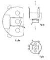
- FIG. 7 shows the prior art with respect to the grating 4.
- the known three identical parts 2 are attached to the so-called convergence pot.
- the field formers made of magnetic material are also on the convergence pot, but on the other side of the pot base. 7 with two rings around the passage openings of the outer rays, which are called shunts.
- Strips 8, which are known as enhancers, are arranged on both sides of the passage opening of the central jet.
- Fig. 7a is the front view in the direction x
- Fig. 7c shows the view from the direction z.
- the partial section in FIG. 7b shows how the parts 2
- the three parts 2 replaced by one or two parts 10 ... 14, but these parts are also designed in such a way that they affect the function of the field former, namely the effect of the deflecting fat on the deflecting unit to match all three rays, evenly.
- Figures 8 and 9 give two exemplary embodiments.
- the parts 15 and 16 are at least partially made of magnetic material.
- these parts 15, 16 have, in comparison to parts 10 to 14, flange-like, additional surfaces by which they are supplemented in such a way that they can assume the function of field formation.
- Dimensions and shape are also determined by calculation and experiment depending on the conditions of the electrode structure.
- FIGS. Further design options arise if the comprehensive Part 3 is also included in the optimization.
- the parts e.g. the parts 15 and 16 in FIGS. 8 and 9, in ferromagnetic material, they still succeed in transferring the function of the field shapers 7 and 8.
Landscapes
- Video Image Reproduction Devices For Color Tv Systems (AREA)
- Electron Beam Exposure (AREA)
Abstract
Durch eine besondere Formgebung der Abschirmteile in den Elektroden eines Elektronenstrahlerzeugerssystems von Farbbildröhren wird die Elektronenoptik verbessert. Dadurch wird insbesondere die Twiststreuung vermindert und ein gemeinsamer Schärfepunkt erreicht. Gleichzeitig wird der Aufbau des Elektronenstrahlerzeugersystems durch Verringern der Anzahl der Bestandteile vereinfacht. Anstelle von je drei Ringen sind je ein oder zwei Teile in "Gitter 4" und/oder "Gitter 3" eingesetzt. Bei der Herstellung dieser Teile aus weichmagnestischem Material sind je nach Formgebung zusätzliche Feldformer (Shunts und/oder Enhancers) entbehrlich.A special shape of the shielding parts in the electrodes of an electron gun system for color picture tubes improves the electron optics. This in particular reduces twist scatter and achieves a common focus point. At the same time, the structure of the electron gun system is simplified by reducing the number of components. Instead of three rings, one or two parts are used in "Grid 4" and / or "Grid 3". Depending on the shape, additional field formers (shunts and / or enhancers) are unnecessary when manufacturing these parts from soft magnetic material.
Description
Die Erfindung betrifft eine ELektronenoptik gemäß Oberbegriff des Patentanspruchs 1.The invention relates to electron optics according to the preamble of patent claim 1.
Bei den ersten Farbfernsehröhren bestanden die ELektronenstrahlerzeugersysteme aus nebeneinander angeordneten gleichen rotationssymmetrischen ELektroden für jeden ELektronenstrahL. Später waren bei der sogenannten "unitized gun", in deren Elektrodenaufbau die EinzeLelektroden zusammengefaßt sind, nebeneinanderliegende rotationssymmetrische ELektroden gleicher Funktion zu einer gemeinsamen ELektrode für alle StrahLen zusammengefaßt. SoLche ELektroden sind unsymmetrisch, so daß sie für Außen- und MittenstrahL eine unterschiedliche Umgebung darstellen. Es ist deshalb üblich, diese Unterschiede im Gitter 3 und Gitter 4, welche üblicherweise die ELektroden der HauptfokussierLinse bilden, durch einen für jeden der drei ELektronenstrahLen vorgesehenen individuellen Ring zu verkleinern. Die drei Ringe sind in einem sie umfassenden, als topfförmige Hülle ausgebildeten ELektrodenteiL nebeneinander befestigt. Die Rotationssymmetrie ist somit im Inneren dieser ELektroden für die einzelnen ELektronenstrahLen annähernd vorhanden, beim Ein- und Austritt aus dem Bereich der Ringe haben jedoch Mitten-und AußenstrahLen unterschiedliche Umgebungen. DemzufoLge ist die Form des elektrostatischen Fokussierungsfeldes nicht vollständig rotationssymmetrisch und dies in einem unterschiedlichen Maß für Mitten- und Außenstrahlen.In the first color television tubes, the electron beam generator systems consisted of identical rotationally symmetrical electrodes for each electron beam arranged next to one another. Later, in the so-called "unitized gun", in whose electrode structure the individual electrodes are combined, adjacent, rotationally symmetrical electrodes of the same function were combined to form a common electrode for all beams. Such electrodes are asymmetrical, so that they represent a different environment for external and central beams. It is therefore customary to reduce these differences in grating 3 and grating 4, which usually form the electrodes of the main focusing lens, by means of an individual ring provided for each of the three electron beams. The three rings are encased in a pot-shaped shell formed electrode parts attached side by side. The rotational symmetry is thus approximately present in the interior of these electrodes for the individual electron beams, but when entering and exiting the area of the rings, the center and outside beams have different environments. As a result, the shape of the electrostatic focusing field is not completely rotationally symmetrical and this to a different degree for center and outside beams.
Aufgabe der Erfindung ist es, bei den die elektrostatische FokussierLinse bildenden ELektroden eines ELektronenstrahlerzeugersystems mit zusammengefaßten Einzelsystemen die Unterschiede der FokussierfeLder für Mitten-und Außenstrahlen im Rahmen einer elektronenoptischen Verbesserung des ELektrodenaufbaus zu beseitigen. Dies geschieht durch die im Kennzeichen des Anspruchs 1 angegebenen Maßnahmen. VorteiLhafte AusgestaLtungen der Erfindung sind in den Ansprüchen 2 bis 6 enthalten.The object of the invention is to eliminate the differences in the focusing fields for center and outside beams in the context of an electron-optical improvement of the electrode structure in the electrodes of an electron beam generator system which form the electrostatic focusing lens. This is done by the measures specified in the characterizing part of claim 1. Advantageous embodiments of the invention are contained in
Die Erfindung beruht auf dem Grundgedanken, daß die ungleiche Einwirkung der ELektronenoptik auf Mitten- und AußenstrahL durch Einführung komplementärer Unsymmetrien mit HiLfe freier Parameter, also auf kompensatorische Weise, gründlicher beseitigt werden kann, als dies durch Maßnahmen zur Erweiterung und Ergänzung der Symmetrie im ELektrodenaufbau möglich wäre. Es wurde festgestellt, daß sich solche Verbesserungen der Eigenschaften der Fokussierlinse ergeben, wenn die Rotationssymmetrie des in der Fokussierelektrode auf die ELektronenstrahLen wirkenden elektrostatischen FeLdes in bestimmter Weise und bis zu einem gewissen Grad verlassen wird. Dabei hat sich gezeigt, daß die Streckung der ursprünglich rotationssymmetrischen Felder durch Aufweitung der in bekannten Fokussierelektroden vorhandenen Ringe, welche sich innerhalb des umfassenden Elektrodenteils der beiden die FokussierLinse bildenden Elektroden (Gitter 3 und Gitter 4) befinden, den Twisteffekt vermindert, wenn die Aufweitung der Ringe in Richtung der Vertikalablenkung erfolgt, so daß aus den Ringen Ellipsen mit einem größeren Durchmesser senkrecht zu der Ebene, in welcher die ELektronenstrahLen verlaufen, entstehen. Unter Twist wird in diesem Zusammenhang der Winkel zwischen der HorizontaLen und den von den drei ELektronenstrahLen bei horizontaler AbLenkung durch das MagnetfeLd des Ablenkjoches geschriebenen Linien auf dem Bildschirm verstanden. Die Verminderung des Twistes durch Aufweitung der Ringe in Richtung der Vertikalablenkung ist insofern erklärbar, als die Lagetoleranzen der ELektronenstrahLen dann in Richtung der größeren ELLipsenachse weniger stark eingehen. EbenfaLLs schwächer wirken sich Unterschiede der Systemkomponenten auf die Schärfespannung aus. Als Schärfespannung wird die am "Gitter 3" vorhandene Spannung gegen Massenpotential verstanden, bei welcher der betreffende StrahL auf dem Schirm fokussiert ist. Bei den zusammengefaßten Elektroden einer "unitized gun"ist die "Gitter 2"-Spannung nicht mehr für jeden StrahL einzeln einstellbar, weshalb auch hohe Anforderungen an die Gleichheit der Fokussierfelder gestellt werden müssen.The invention is based on the basic idea that the unequal action of the electron optics on the center and outside beam can be eliminated more thoroughly by introducing complementary asymmetries with the help of free parameters, that is to say in a compensatory manner, than can be done by measures to expand and supplement the symmetry in the electrode structure would. It has been found that such improvements in the properties of the focusing lens result if the rotational symmetry of the electrostatic field acting on the electron beams in the focusing electrode is left in a certain manner and to a certain degree. It has been shown that the stretching of the originally rotationally symmetrical fields by widening the rings present in known focusing electrodes, which are located within the comprehensive electrode part of the two electrodes forming the focusing lens (
Insbesondere bei DünnhaLsröhren sind diese Verbesserungen von großer Bedeutung, denn die ELektronenstrahLen sind eng benachbart und die FokussierungsLinse hat einen vergleichsweise kleinen Durchmesser.These improvements are particularly important for thin-tube tubes, because the electron beams are closely adjacent and the focusing lens has a comparatively small diameter.
Eine weitere MögLichkeit zur Vereinfachung der ELektrode auf der "Gitter 4"-Seite der FokussierLinse, welche üblicherweise die zum AusgLeich des magnetischen Ablenkfeldes dienenden FeLdformer (Shunts und Enhancers) trägt, besteht nach einer Ausgestaltung der Erfindung darin, daß TeiLe der ELektrode selbst aus weichmagnetischem MateriaL bestehen, so daß die auf der AußenfLäche der ELektroden angeschweißten weichmagnetischen FeLdformer vollständig oder teilweise entbehrlich sind. Das bringt eine weitere Vereinfachung bei der HersteLLung des Elektranenstrahlerzeugersystems mit sich. Die ELektrode mit Feldformer besteht dann nicht mehr aus acht sondern aus fünf, im günstigsten FaLL sogar nur noch aus drei TeiLen.Another possibility for simplifying the electrode on the "grating 4" side of the focusing lens, which usually carries the field shapers (shunts and enhancers) used to compensate for the magnetic deflection field, according to one embodiment of the invention consists in that parts of the electrode itself are made of soft magnetic Materials exist so that the soft magnetic field formers welded onto the outer surface of the electrodes are completely or partially unnecessary. This brings a further simplification in the manufacture of the electron gun system. The elec- trode with field former then no longer consists of eight but five, in the cheapest case even only three parts.
Die Erfindung ist nachstehend anhand der Figuren beschrieben. Es zeigen:The invention is described below with reference to the figures. Show it:
- Fig. 1a den Längsschnitt durch ein bekanntes ELektronenstrahlerzeugersystem;1a shows the longitudinal section through a known electron gun system;
- Fig. 1b die Vorderansicht des bekannten ELektronenstrahLerzeugersystems (Ansicht Z gemäß Fig. 1a);1b shows the front view of the known electron beam generator system (view Z according to FIG. 1a);
- Fig. 1c einen Querschnitt durch die Gitter 3-Elektrode des bekannten Systems gemäß Fig. 1a (Schnitt AB in Fig. 1e);1c shows a cross section through the grid 3-electrode of the known system according to FIG. 1a (section AB in FIG. 1e);
- Fig. 1d einen Querschnitt durch die Gitter 4-Elektrode des bekannten Systems gemäß Fig. 1a (Schnitt CD in Fig. 1b);1d shows a cross section through the grid 4-electrode of the known system according to FIG. 1a (section CD in FIG. 1b);
- Fig. 1e die Ansicht eines TeiLs der Gitter 3-ELektrode des bekannten Systems (Ansicht V in Fig. 1a);Fig. 1e the view of a part of the grid 3-electrode of the known system (view V in Fig. 1a);
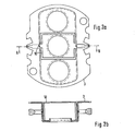
- Fig. 2a die Vorderansicht des AusführungsbeispieLs A der Erfindung (Teile in topfförmiger Hülle)2a shows the front view of the embodiment A of the invention (parts in a pot-shaped shell)
- Fig. 2b den Schnitt AB aus Fig. 2a;2b shows the section AB from FIG. 2a;
- Fig. 3a die Vorderansicht des Ausführungsbeispiels B der Erfindung;3a shows the front view of embodiment B of the invention;
- Fig. 3b den Schnitt AB aus Fig. 3a;3b shows the section AB from FIG. 3a;
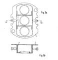
- Fig. 4a die Vorderansicht des AusführungsbeispieLs C der Erfindung;4a shows the front view of embodiment C of the invention;
- Fig. 4b den Schnitt AB aus Fig. 4a;4b shows the section AB from FIG. 4a;
- Fig. 5a die Vorderansicht des AusführungsbeispieLs D der Erfindung;5a shows the front view of embodiment D of the invention;
- Fig. 5b den Schnitt CD aus Fig. 5a;5b shows the section CD from FIG. 5a;
- Fig. 6a die Vorderansicht des Ausführungsbeispiels E der Erfindung;6a shows the front view of embodiment E of the invention;
- Fig. 6b den Schnitt CD aus Fig. 6a;6b shows the section CD from FIG. 6a;
- Fig. 7a die Vorderansicht (Ansicht x) der Gitter 4-ELektrode eines bekannten Elektronenstrahlerzeugersystems;7a shows the front view (view x) of the grid 4-electrode of a known electron gun system;
- Fig. 7b die Seitenansicht der Gitter 4-Elektrode gemäß Fig. 7a;7b shows the side view of the grid 4-electrode according to FIG. 7a;
- Fig. 7c die Ansicht z der Gitter 4-ELektrode gemäß Fig. 7b;7c shows the view z of the grid 4 electrode according to FIG. 7b;
- Fig. 8a die Vorderansicht des AusführungsbeispieLs F der Erfindung in der DarsteLLungsweise von Fig. 7a;FIG. 8a shows the front view of the exemplary embodiment F of the invention as shown in FIG. 7a;
- Fig. 8b die Seitenansicht des Ausführungsbeispiels F gemäß Fig. 8a;8b shows the side view of embodiment F according to FIG. 8a;
- Fig. 8c die Ansicht z des AusführungsbeispieLs F gemäß Fig. 8b;8c shows the view z of the exemplary embodiment F according to FIG. 8b;
- Fig. 9a die Vorderansicht des AusführungsbeispieLs G der Erfindung in der DarsteLLungsweise von Fig.7a;FIG. 9a shows the front view of the exemplary embodiment G of the invention as shown in FIG. 7a;
- Fig. 9b die Seitenansicht des Ausführungsbeispiels G gemäß Fig. 9a;FIG. 9b shows the side view of the exemplary embodiment G according to FIG. 9a;
- Fig. 9c die Ansicht z des AusführungsbeispieLs G gemäß Fig. 9b.9c shows the view z of the exemplary embodiment G according to FIG. 9b.
In den Figuren 1a bis 1e ist ein bekanntes ELektronenstrahlerzeugersystem gezeigt. üblicherweise wird 5 aLs "Gitter 3" und 6 als "Gitter 4" bezeichnet. "Gitter 4" (6) weist gegenüber "Gitter 3" (5) ein stark unterschiedliches elektrisches PotentiaL auf, so daß sich zwischen 5 und 6 eine elektrostatische Fokussierlinse ausbildet. Fig. 1b zeigt in der Draufsicht auf das "Gitter 4" (6) die FeLdformer 7 und 8 (Shunts 7 und Enhancers 8). Diese feldformenden MitteL bewirken, daß das magnetische Ablenkfeld einer auf dem RöhrenhaLs angebrachten AbLenkeinheit auf die drei durch die öffnungen 9 tretenden ELektronenstrahLen gleichstark einwirkt.A known electron gun system is shown in FIGS. 1a to 1e. 5 aLs "
Auch Fig. 7 zeigt ein bekanntes Elektronenstrahlerzeugersystem gemäß dem Stand der Technik. Die drei gleichen TeiLe 2 sind dort am sogenannten Konvergenztopf 4 befestigt.7 also shows a known electron gun system according to the prior art. The three
In Figur 2a sind zwei gleiche TeiLe 10 in der topfförmigen HüLLe 3 befestigt. In Figur 2b ist die Höhe dieser TeiLe 10 entsprechend der Tiefe des in TeiL 3 eingeprägten Topfes gewählt. Diese Höhe der TeiLe kann, wie die Figuren 5b und 6b zeigen, auch veränderlich sein.In FIG. 2a, two
In Figur 3a handelt es sich ebenfalls um zwei gleiche TeiLe 11, welche jedoch mit Ihren FLanschen auf der Seite der AußenstrahLen befestigt sind.In FIG. 3a there are also two
In Figur 4a, b und Figur 5a, b sind AusführungsbeispieLe mit nur je einem TeiL 12 bzw. 13 dargestellt, während Fig. 6a, b noch ein Beispiel mit zwei gleichen, aber unsymmetrischen Teilen 14 zeigt. In allen BeispieLen nach Fig. 2 bis Fig. 6 sind die TeiLe 10 ... 14 in der topfförmigen Hülle 3 befestigt. Eine gleichwertige MögLichkeit der Befestigung besteht darin, daß die TeiLe 10 ... 14 auf einer Platine 1 (s.a. Fig. 1a) befestigt sind, weLche an der topfförmigen Hülle angebracht wird. Weitere konstruktive Varianten sind möglich, wobei wesentlich ist, daß das oder die TeiLe in der topfförmigen Hülle mit ihren parallel zu den Wandflächen des Topfes verlaufenden Flächen so angeordnet sind, daß die drei ELektronenstrahLen im Topf gegeneinander abgeschirmt sind. Die genauen Abmessungen und die Formgebung der TeiLe erfolgt unter Berücksichtigung von Versuchs- und Rechenergebnissen.FIGS. 4a, b and 5a, b show exemplary embodiments with only one
In der Figur 7 ist der Stand der Technik bezüglich des Gitters 4 gezeigt. Das sowohl bei dem bekannten als auch beim erfindunosgemäßen Elektronenstrahlerzeugersystem bei Gitter 4 wie bei Gitter 3 vorhandene umfassende Teil, die topfförmige Hülle 3,ist der übersichtlichkeit halber nicht eingezeichnet. Im Gitter 4 sind die bekannten drei gleichen Teile 2 am sogenannten Konvergenztopf angebracht. EbenfaLLs am Konvergenztopf, jedoch an der anderen Seite des Topfbodens, befinden sich die Feldformer aus magnetischem Werkstoff. Mit 7 sind zwei Ringe um die Durchtrittsöffnungen der Außenstrahlen bezeichnet, welche Shunts genannt werden. Beiderseits der Durchtrittsöffnung des Mittelstrahles sind Streifen 8 angeordnet, die unter der Bezeichnung Enhancer bekannt sind. Fig. 7a ist die Vorderansicht in Richtung x, Fig. 7c zeigt die Ansicht aus Richtung z. Der Teilschnitt in Fig. 7b zeigt, wie die TeiLe 2FIG. 7 shows the prior art with respect to the grating 4. The comprehensive part present in the known as well as in the inventive electron beam generator system in the case of the grid 4 and the
außen am Topfboden über den öffnungen 9 für den Durchtritt der ELektronenstrahLen angeordnet sind.are arranged on the outside of the pot bottom above the
Nach einer weiteren AusbiLdung der Erfindung werden nun nicht nur die drei TeiLe 2 durch ein oder zwei TeiLe 10 ... 14 ersetzt, sondern auch diese TeiLe in solcher Weise ausgestaltet, daß sie die Funktion der Feldformer, nämlich die Wirkung des Ablenkfetdes der AbLenkeinheit auf alle drei StrahLen zu vergleichmäßigen, miterfüllen.According to a further embodiment of the invention, not only are the three
Die Figuren 8 und 9 geben dazu zwei AusführungsbeispieLe. Die TeiLe 15 und 16 sind zumindest teilweise aus magnetischem Werkstoff. Diese TeiLe 15, 16 haben, um die Aufgabe der FeLdformung miterfüllen zu können, im VergLeich zu den TeiLen 10 bis 14 flanschartige, zusätzliche FLächen, durch welche sie so ergänzt sind, daß sie die Funktion der FeLdformung übernehmen können. Abmessungen und Formgebung werden auch hier je nach den Gegebenheiten des ELektrodenaufbaus durch Berechnung und Versuch bestimmt.Figures 8 and 9 give two exemplary embodiments. The
Durch Verwendung der AbschirmbLeche 10 bis 14 anstatt der rotationssymmetrischen Ringe 2 erhält man zusätzliche Freiheitsgrade zur GestaLtung der die elektrostatische FokussierLinse 5/6 mitbestimmenden elektrischen FeLder in den umfassenden TeiLen 3. Die Figuren 2 ... 6 geben einige AusführungsmögLichkeiten. Weitere GestaLtungsmögLichkeiten ergeben sich, wenn auch das umfassende TeiL 3 in die Optimierung mit einbezogen wird. Durch erweiternde AusgestaLtung der Teile, z.B. die TeiLe 15 und 16 in Fig. 8 und 9, in ferromagnetischem Werkstoff gelingt es, ihnen noch die Funktion der FeLdformer 7 und 8 zu übertragen.By using the
VorteiLe der erfindungsgemäßen Bauweise sind:
- 1. der mechanische Aufbau der die FokussierLinse bildenden Elektroden wird einfacher. Es werden z.B. vier TeiLe entbehrlich, wenn im "
Gitter 3"-Oberteil und im "Gitter 4" entsprechend Fig. 4oder 5 statt derje drei Ringe 2 nur je ein U-förmiges TeiL verwendet wird. - 2. Die Twiststreuung wird eingeengt. Wenn infolge von MontagetoLeranzen die ELektrodenöffnungen versetzt oder die ELektroden verdreht sind, wird durch den vergrößerten Abstand der ELektronenstrahLen zum umfassenden TeiL 3 die Toleranzempfindlichkeit gegen Verdrehen herabgesetzt.
- 3. Der Bereich der gemeinsamen Schärfespannung wird größer. In der Fertigung hat sich gezeigt, daß beim TestbiLd mit Gitterraster in einer Farbe ein gemeinsamer Schärfepunkt der HorizontaL- und Vertikal Linien nur schwer zu erreichen ist. Durch
Verwendung der TeiLe 10 ... 16 und hiermit eines der FokussierLinse überlagerten, nicht rotationssymmetrischen FeLdes wurde ein gemeinsamer Schärfepunkt erreicht. - 4. Bei Anbringung der AbschirmbLeche, die ganz oder teilweise aus einem ferromagnetischen Material bestehen, können die bisher verwendeten Feldformer (Shunts und Enhancers) als feldformende MitteL entfallen.
- 1. The mechanical structure of the electrodes forming the focusing lens becomes simpler. For example, four parts can be dispensed with if only one U-shaped part is used instead of the three
rings 2 in the "grid 3" upper part and in the "grid 4" according to FIG. 4 or 5. - 2. The twist scatter is narrowed. If the electrode openings are offset or the electrodes are twisted as a result of mounting tolerances, the increased sensitivity of the electron beams to the
comprehensive part 3 reduces the tolerance sensitivity to twisting. - 3. The area of the common focus is increasing. It has been shown in production that in the test picture with grid grid in one color it is difficult to reach a common focus point of the horizontal and vertical lines. A common focus point was achieved by using
parts 10 ... 16 and hereby a non-rotationally symmetrical field superimposed on the focusing lens. - 4. If the shielding sheets, which are made entirely or partially of a ferromagnetic material, are attached, the previously used field formers (shunts and enhancers) as field-forming means can be omitted.
BezugszeichenListe
- 1 ebenes Blech
- 2 Ring
- 3 umfassendes TeiL
- 4 Topf ("Konvergenztopf")
- 5
Gitter 3 - 6 Gitter 4
- 7 Shunts
- 8 Enhancers Feldformer
- 9 öffnungen
- 10 AbschirmbLeche in
Gitter 3 - 11 " " " "
- 12 "
- 13 "
- 14 " " " "
- 15 AbschirmbLeche in Gitter 4
- 16 " " "
- 1 flat sheet
- 2 ring
- 3 comprehensive parts
- 4 pot ("convergence pot")
- 5
grids 3 - 6 grids 4
- 7 shunts
- 8 Enhancers field formers
- 9 openings
- 10 shielding sheets in
grid 3 - 11 """"
- 12 "
- 13 "
- 14 """"
- 15 shielding sheets in grid 4
- 16 """
Claims (6)
Applications Claiming Priority (2)
| Application Number | Priority Date | Filing Date | Title |
|---|---|---|---|
| DE19823212248 DE3212248A1 (en) | 1982-04-02 | 1982-04-02 | ELECTRON OPTICS OF THE ELECTRONIC RADIATOR GENERATOR SYSTEM OF A COLOR IMAGE TUBE |
| DE3212248 | 1982-04-02 |
Publications (3)
| Publication Number | Publication Date |
|---|---|
| EP0090989A2 true EP0090989A2 (en) | 1983-10-12 |
| EP0090989A3 EP0090989A3 (en) | 1984-09-12 |
| EP0090989B1 EP0090989B1 (en) | 1988-07-06 |
Family
ID=6160034
Family Applications (1)
| Application Number | Title | Priority Date | Filing Date |
|---|---|---|---|
| EP83102719A Expired EP0090989B1 (en) | 1982-04-02 | 1983-03-18 | Electron-optics of a colour picture tube's electron beam gun |
Country Status (5)
| Country | Link |
|---|---|
| US (1) | US4682073A (en) |
| EP (1) | EP0090989B1 (en) |
| JP (1) | JPS58184243A (en) |
| CA (1) | CA1222276A (en) |
| DE (2) | DE3212248A1 (en) |
Families Citing this family (4)
| Publication number | Priority date | Publication date | Assignee | Title |
|---|---|---|---|---|
| NL8402303A (en) * | 1984-07-20 | 1986-02-17 | Philips Nv | COLOR IMAGE TUBE. |
| JP2661024B2 (en) * | 1986-12-27 | 1997-10-08 | ソニー株式会社 | Cathode ray tube |
| TW392190B (en) * | 1998-05-11 | 2000-06-01 | Koninkl Philips Electronics Nv | Cathode ray tube comprising an electron gun |
| KR100596229B1 (en) * | 1998-09-29 | 2006-09-20 | 엘지전자 주식회사 | Electron Gun of Color Cathode Ray Tube |
Citations (6)
| Publication number | Priority date | Publication date | Assignee | Title |
|---|---|---|---|---|
| US3448316A (en) * | 1967-01-14 | 1969-06-03 | Sony Corp | Cathode ray tube |
| US3840765A (en) * | 1972-09-26 | 1974-10-08 | Tokyo Shibaura Electric Co | Shielding member between only the control and side beams in a color cathode ray tube |
| GB2020480A (en) * | 1978-05-01 | 1979-11-14 | Rca Corp | Colour picture tube having electron gun |
| GB2027269A (en) * | 1978-07-25 | 1980-02-13 | Matsushita Electronics Corp | In-line electron gun assembly |
| US4208610A (en) * | 1978-06-09 | 1980-06-17 | Zenith Radio Corporation | Television picture tubes having an electron gun with aperture electrode shielding means |
| US4225804A (en) * | 1978-04-22 | 1980-09-30 | Gte Sylvania N.V. | Cathode ray tube coma correction device |
Family Cites Families (6)
| Publication number | Priority date | Publication date | Assignee | Title |
|---|---|---|---|---|
| US3928785A (en) * | 1971-11-23 | 1975-12-23 | Adrian W Standaart | Single gun, multi-screen, multi-beam, multi-color cathode ray tube |
| US3866080A (en) * | 1973-08-08 | 1975-02-11 | Rca Corp | Inline electron gun having magnetically permeable plates for enhancing convergence of electron beams |
| JPS5251863A (en) * | 1975-10-22 | 1977-04-26 | Mitsubishi Electric Corp | Electronic gun for color picture tube |
| US4142131A (en) * | 1975-11-12 | 1979-02-27 | Hitachi, Ltd. | Color picture tube |
| JPS5292473A (en) * | 1976-01-30 | 1977-08-03 | Mitsubishi Electric Corp | Main lens electric field forming method of inline type 3 beam electron gun |
| NL7802129A (en) * | 1978-02-27 | 1979-08-29 | Philips Nv | DEVICE FOR DISPLAYING COLORED IMAGES. |
-
1982
- 1982-04-02 DE DE19823212248 patent/DE3212248A1/en not_active Withdrawn
-
1983
- 1983-03-18 DE DE8383102719T patent/DE3377311D1/en not_active Expired
- 1983-03-18 EP EP83102719A patent/EP0090989B1/en not_active Expired
- 1983-03-31 CA CA000425030A patent/CA1222276A/en not_active Expired
- 1983-04-01 JP JP58055361A patent/JPS58184243A/en active Pending
-
1986
- 1986-11-06 US US06/928,663 patent/US4682073A/en not_active Expired - Fee Related
Patent Citations (6)
| Publication number | Priority date | Publication date | Assignee | Title |
|---|---|---|---|---|
| US3448316A (en) * | 1967-01-14 | 1969-06-03 | Sony Corp | Cathode ray tube |
| US3840765A (en) * | 1972-09-26 | 1974-10-08 | Tokyo Shibaura Electric Co | Shielding member between only the control and side beams in a color cathode ray tube |
| US4225804A (en) * | 1978-04-22 | 1980-09-30 | Gte Sylvania N.V. | Cathode ray tube coma correction device |
| GB2020480A (en) * | 1978-05-01 | 1979-11-14 | Rca Corp | Colour picture tube having electron gun |
| US4208610A (en) * | 1978-06-09 | 1980-06-17 | Zenith Radio Corporation | Television picture tubes having an electron gun with aperture electrode shielding means |
| GB2027269A (en) * | 1978-07-25 | 1980-02-13 | Matsushita Electronics Corp | In-line electron gun assembly |
Also Published As
| Publication number | Publication date |
|---|---|
| DE3377311D1 (en) | 1988-08-11 |
| JPS58184243A (en) | 1983-10-27 |
| DE3212248A1 (en) | 1983-10-06 |
| CA1222276A (en) | 1987-05-26 |
| EP0090989A3 (en) | 1984-09-12 |
| EP0090989B1 (en) | 1988-07-06 |
| US4682073A (en) | 1987-07-21 |
Similar Documents
| Publication | Publication Date | Title |
|---|---|---|
| DE2608463C3 (en) | Inline color picture tube | |
| DE2938769C2 (en) | In-line electron beam generation system | |
| DE2850411C2 (en) | Electron gun in a cathode ray tube | |
| EP0218920B1 (en) | Omega-type electron energy filter | |
| EP1995758B1 (en) | Monochromator and charged particle beam source with monochromator | |
| DE69210943T2 (en) | Picture tube deflection unit with vertical deflection coils of the semi-saddle type | |
| DE3107634A1 (en) | COLOR IMAGE TUBES WITH LOW-ABERRATION RADIATION FOCUSING LENS | |
| DD262525A5 (en) | COLOR IMAGE REPRODUCTION SYSTEM | |
| DE69311775T2 (en) | ELECTRON BEAM DEFLECTIVE LENS FOR COLOR CATHODE BEAM | |
| DE69013183T2 (en) | Color picture tube system with reduced stain growth. | |
| DE69510968T2 (en) | Color cathode ray tube | |
| DE68918405T2 (en) | Multi-step focusing electron generation system for cathode ray tubes. | |
| EP0090989A2 (en) | Electron-optics of a colour picture tube's electron beam gun | |
| DE69506080T2 (en) | IMAGE DISPLAY DEVICE WITH ELECTRONIC CANNON, AND ELECTRONIC CANNON FOR USE IN SUCH A DEVICE | |
| DE3614429C2 (en) | ||
| DE68913585T2 (en) | Image display tube with a spiral focusing lens with a non-rotationally symmetrical lens element. | |
| DD238473A5 (en) | SLOTTED MASK ELECTRON CANE FOR CATALYST RADIATION TUBES | |
| DE4431335B4 (en) | Electron gun for a color picture tube | |
| DE69025634T2 (en) | Color cathode ray tube | |
| EP0138264B1 (en) | Colour display tube | |
| DE3216039C2 (en) | Electron beam generating system of a cathode ray tube | |
| DE2513281C2 (en) | Multi-beam electron gun for color cathode ray tubes | |
| DE3043048C2 (en) | ||
| DE3123301C2 (en) | Device for adjusting electron beams from a cathode ray tube | |
| DE2412541B2 (en) | Beam generator system for color picture tubes |
Legal Events
| Date | Code | Title | Description |
|---|---|---|---|
| PUAI | Public reference made under article 153(3) epc to a published international application that has entered the european phase |
Free format text: ORIGINAL CODE: 0009012 |
|
| AK | Designated contracting states |
Designated state(s): DE FR GB IT NL |
|
| PUAL | Search report despatched |
Free format text: ORIGINAL CODE: 0009013 |
|
| AK | Designated contracting states |
Designated state(s): DE FR GB IT NL |
|
| 17P | Request for examination filed |
Effective date: 19841017 |
|
| RAP1 | Party data changed (applicant data changed or rights of an application transferred) |
Owner name: STANDARD ELEKTRIK LORENZ AKTIENGESELLSCHAFT Owner name: ALCATEL N.V. |
|
| RAP3 | Party data changed (applicant data changed or rights of an application transferred) |
Owner name: STANDARD ELEKTRIK LORENZ AKTIENGESELLSCHAFT Owner name: ALCATEL N.V. |
|
| GRAA | (expected) grant |
Free format text: ORIGINAL CODE: 0009210 |
|
| AK | Designated contracting states |
Kind code of ref document: B1 Designated state(s): DE FR GB IT NL |
|
| ITF | It: translation for a ep patent filed | ||
| GBT | Gb: translation of ep patent filed (gb section 77(6)(a)/1977) | ||
| REF | Corresponds to: |
Ref document number: 3377311 Country of ref document: DE Date of ref document: 19880811 |
|
| ET | Fr: translation filed | ||
| RAP2 | Party data changed (patent owner data changed or rights of a patent transferred) |
Owner name: NOKIA GRAETZ GESELLSCHAFT MIT BESCHRAENKTER HAFTUN |
|
| NLT2 | Nl: modifications (of names), taken from the european patent patent bulletin |
Owner name: NOKIA GRAETZ GESELLSCHAFT MIT BESCHRAENKTER HAFTUN |
|
| REG | Reference to a national code |
Ref country code: FR Ref legal event code: TP |
|
| PG25 | Lapsed in a contracting state [announced via postgrant information from national office to epo] |
Ref country code: GB Effective date: 19890318 |
|
| NLS | Nl: assignments of ep-patents |
Owner name: NOKIA GRAETZ GMBH TE PFORZHEIM, BONDSREPUBLIEK DUI |
|
| PLBE | No opposition filed within time limit |
Free format text: ORIGINAL CODE: 0009261 |
|
| STAA | Information on the status of an ep patent application or granted ep patent |
Free format text: STATUS: NO OPPOSITION FILED WITHIN TIME LIMIT |
|
| 26N | No opposition filed | ||
| PG25 | Lapsed in a contracting state [announced via postgrant information from national office to epo] |
Ref country code: NL Effective date: 19891001 |
|
| GBPC | Gb: european patent ceased through non-payment of renewal fee | ||
| NLV4 | Nl: lapsed or anulled due to non-payment of the annual fee | ||
| PG25 | Lapsed in a contracting state [announced via postgrant information from national office to epo] |
Ref country code: FR Free format text: LAPSE BECAUSE OF NON-PAYMENT OF DUE FEES Effective date: 19891130 |
|
| PG25 | Lapsed in a contracting state [announced via postgrant information from national office to epo] |
Ref country code: DE Effective date: 19891201 |
|
| REG | Reference to a national code |
Ref country code: FR Ref legal event code: ST |