EP0090797B1 - Electro-hydraulic timing control system for injection pumps of fuel injection internal-combustion engines - Google Patents
Electro-hydraulic timing control system for injection pumps of fuel injection internal-combustion engines Download PDFInfo
- Publication number
- EP0090797B1 EP0090797B1 EP83890050A EP83890050A EP0090797B1 EP 0090797 B1 EP0090797 B1 EP 0090797B1 EP 83890050 A EP83890050 A EP 83890050A EP 83890050 A EP83890050 A EP 83890050A EP 0090797 B1 EP0090797 B1 EP 0090797B1
- Authority
- EP
- European Patent Office
- Prior art keywords
- solenoid valve
- actuator
- injection
- pressure
- valve
- Prior art date
- Legal status (The legal status is an assumption and is not a legal conclusion. Google has not performed a legal analysis and makes no representation as to the accuracy of the status listed.)
- Expired
Links
Images


Classifications
-
- F—MECHANICAL ENGINEERING; LIGHTING; HEATING; WEAPONS; BLASTING
- F02—COMBUSTION ENGINES; HOT-GAS OR COMBUSTION-PRODUCT ENGINE PLANTS
- F02D—CONTROLLING COMBUSTION ENGINES
- F02D1/00—Controlling fuel-injection pumps, e.g. of high pressure injection type
- F02D1/16—Adjustment of injection timing
- F02D1/18—Adjustment of injection timing with non-mechanical means for transmitting control impulse; with amplification of control impulse
- F02D1/183—Adjustment of injection timing with non-mechanical means for transmitting control impulse; with amplification of control impulse hydraulic
-
- F—MECHANICAL ENGINEERING; LIGHTING; HEATING; WEAPONS; BLASTING
- F02—COMBUSTION ENGINES; HOT-GAS OR COMBUSTION-PRODUCT ENGINE PLANTS
- F02B—INTERNAL-COMBUSTION PISTON ENGINES; COMBUSTION ENGINES IN GENERAL
- F02B3/00—Engines characterised by air compression and subsequent fuel addition
- F02B3/06—Engines characterised by air compression and subsequent fuel addition with compression ignition
Definitions
- the invention relates to an electronic-hydraulic control system for setting the start of delivery of injection pumps for injection internal combustion engines, in particular for fuel injection in a diesel engine, with a memory for the program to be executed with a processor having data inputs to which sensors for the speed selector or accelerator pedal position and operating parameters of the Machine, such as temperatures and pressures, as well as speed and torque, if any, are connected, and with outputs, to which solenoid valves for one engaging against the action of a spring in the transmission mechanism for driving the injection pump (s), are driven by an internal combustion engine
- a hydraulic actuator which can be acted upon by a pump and is designed as a single-acting cylinder is connected to the pump, the working space of which is connected via a solenoid valve arrangement to the pressure medium source or to a return line is inducible, a pressure accumulator being connected to the pressure medium source via a check valve opening to the pressure accumulator.
- the injection systems currently used for injection internal combustion engines consist of an injection unit, injection lines, and nozzle holders and nozzles.
- the injection pressure generated in the injection pump spreads through the injection lines at the speed of sound to the nozzle holders. Due to the constant speed of sound, the time required for this is independent of the speed of the internal combustion engine. This means that with increasing speed, the pressure wave, based on the position of the piston of the internal combustion engine, always reaches the nozzle-nozzle holder combination later.
- this is achieved via a centrifugal speed sensor or a speed measuring device, which generates a signal proportional to the speed, which rotates the injection pump shaft relative to its drive shaft.
- the torque required for the rotation of the injection pump shaft relative to its drive shaft fluctuates periodically and reaches very high peak values, since the entire drive torque for the camshaft of the injection pump is passed through the injection adjuster mechanism.
- the adjusting mechanism which is based on the principle of relative rotation from the injection pump shaft to the drive shaft, must be able to deliver a large torque.
- the hydraulics are a technically sensible work system. Spray adjuster systems that work with hydraulic adjustment are known and e.g. in Diesel & Gas Turbine Worldwide, November 1981, pages 61 and 65: Two New Controls For Vehicie Diesels, and in SAE Paper 790901, M. Straubel, R.Schwartz and K.Hummel: The Robert Bosch In-Line Pump for Diesel Engines, Type MW, Design, Application and Further Development, listed and described.
- An electronic-hydraulic control system of the type specified is known from DE-A-29 32 672.
- the line separated from the pressure side of the pressure medium pump by a check valve, to which the pressure accumulator is connected, is the only pressure medium supply line for the hydraulically controlled control circuit.
- the pressure in the pressure accumulator is therefore dependent on the last delivery pressure of the pressure medium pump before the internal combustion engine is switched off. This pressure will be low in particular if pressure medium was still used for an actuating process immediately before the internal combustion engine was switched off. The greatest possible pressure from the pressure accumulator is therefore not always available for a later cold start process.
- Another disadvantage of the known arrangement is that a single, three-position solenoid valve is used.
- the invention aims to avoid these disadvantages and, in the case of an actuating system of the type specified at the outset, is that the working space of the actuator can be connected to the pressure medium source or to the pressure accumulator either by means of a throttle or by means of a further solenoid valve the return line can be connected, with all solenoid valves being separately controllable and in the de-energized state the solenoid valve producing the connection to the throttle open and the solenoid valve connecting the return line is closed.
- the separate solenoid valve which serves as an inlet valve, allows an optional supply to the working area of the actuator either while it is running
- a separate drain valve also designed as a solenoid valve, is provided for relieving the pressure in the working space of the actuator in the course of control processes.
- the inlet valve establishes an open connection with the pressure side of the pressure medium pump and the outlet valve is closed. This ensures a simple speed-dependent adjustment of the injection time via the delivery pressure of the pressure medium pump which is dependent on the speed of the internal combustion engine.
- the pressure medium source which has a pump driven by the internal combustion engine, supplies the hydraulic actuator with information about the rotational speed of the internal combustion engine.
- the electronic control device having the processor can intervene at any time by switching the solenoid valves in order to set the start of delivery of the injection pump differently from the value which is merely caused by the speed of the internal combustion engine .
- the associated solenoid valve can be switched to the pressure accumulator with the starter switch, the pressure of which then acts immediately on the hydraulic actuator, so that the a satisfactory starting process, desired early delivery of the injection pump is achieved.
- a control valve is connected to the connecting line between the throttle and the first-mentioned solenoid valve, the output of which is connected to a return line, possibly via a further throttle.
- Simple, electromagnetically controllable shut-off valves can be used to establish the connection for the application of pressure medium to the working space of the hydraulic actuator by two separately controllable solenoid valves, the outputs of which are provided together with the, for selectively connecting the working space of the actuator with the throttle or with the pressure accumulator Work space and connected to the input of the other solenoid valve.
- a changeover valve with two inputs and one output can be provided for the optional connection of the working space of the actuator with the throttle or with the pressure accumulator.
- the pressure medium source can have a separate pump driven by the internal combustion engine, but a particularly economical solution is that the pressure medium source is formed by the lubricant pump of the internal combustion engine and that lubricant is led via the return line to the transmission mechanism coupled to the actuator. There is therefore no need for a separate hydraulic pump and because the pressure medium is lubricating oil, the pressure medium can be used for the lubrication of mechanically moving parts of the actuating system.
- a technically simple, mechanically favorable and space-saving design can be achieved with an actuating system in which the transmission mechanism (injection adjuster) for driving the injection pump (s) at the end of the camshaft thereof and on a shaft end which is coaxial with it and connected to the drive flange of the injection pump has an external toothing with a different pitch and a sliding sleeve bridging these two external toothings, equipped with corresponding internal toothings and adjustable in the axial direction, which is pressed into an end position by a spring, the injection adjuster being accommodated in a hollow cylindrical housing and in the housing by an end wall The same extends coaxially to the housing shell, a guide sleeve surrounding the sliding sleeve and spring at a distance, between which and the housing shell a working space for an annular piston of the actuator is formed, which is connected via a bearing with d it is coupled in operation with the rotating sleeve for axial displacement of the same.
- the housing jacket is formed at least in an area of its circumference with a greater wall thickness and has incorporated channels, that the solenoid valves are attached and connected to the outside of this area, that the channel connecting the solenoid valves on the front side of the Workspace opens and that the exit of the further Solenoid valve opens into the interior of the housing facing away from the working space, in which the bearing, the sliding sleeve, the spring and the toothings are located, the return line leading to the pressure medium source being connected to the lower area of the interior in the installed position of the spray adjuster.
- the solenoid valves can be attached directly to the spray adjuster and it is found that there is a minimum of pipes.
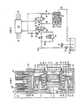
- FIG. 1 shows a spray adjuster for the actuating system according to the invention in axial section; 2 shows a diagram with the dependence of the start of delivery of the injection pump on the engine speed; 3 shows a diagram with the relationship between torque and speed of the internal combustion engine with the start of delivery of the injection pump as a parameter; 4, 5 and 6 schematically each show an embodiment of the electronic-hydraulic control system according to the invention, and FIG. 7 shows a diagram with the relationship between pressure medium pressure and engine speed when the pressure medium is removed from the lubricating oil circuit of the engine.
- the drive-side end of the camshaft 1 of an injection pump 2 has an oblique external toothing 3.
- a hollow stub shaft 7 connected to a drive flange 6 is rotatably mounted on the extended end 5 of the camshaft 1 and secured against axial movement by means of a screw 8.
- the shaft end 7 has a straight external toothing 9 in the vicinity of its end adjacent to the oblique external toothing 3.
- the two external toothings 3 and 9 are overlapped by a sliding sleeve 10, each of which has a corresponding internal toothing 11 or 12 meshing with one of these external toothings.
- the working space for the piston 17 is delimited by an inner end wall and an inner circumferential wall of the housing 4 and by a guide bush 18 inserted into the housing 4.
- the guide bushing 18 and the housing 4 are connected to the injection pump 2 by means of screws 19.
- the housing 4 of the injection adjuster is closed with a cover 20.
- the piston 17 carries two seals 21, 22, which seal against the guide bush 18 or against the inner peripheral wall of the housing 4.
- a 3/2-way valve 23 and a 2/2-way valve 24 are attached to the housing 4 and control the inflow and outflow of the pressure medium to and from the piston 17. From the pressure medium inlet 25, the pressure medium passes through a bore 26 to the valve 23. If the plate 27 is raised by passage of current through the winding of the valve 23 designed as a solenoid valve, the pressure medium passes through a bore 28 to the end face of the piston 17 and displaces it, the roller bearing 16, the tubular support 15 and thus also the sliding sleeve 10 against the force of the spring 13 in the direction of the drive flange 6. Further bores 29 and 30 are also filled with pressure medium, which, however, cannot flow out as long as the plate 31 also Valve 24 designed as a solenoid valve remains in the closed position.
- the piston 17 is moved in the direction of the drive flange 6 until the plate 27 of the valve 23 is closed or until a state of equilibrium is established between the force exerted by the pressure medium pressure on the end face of the piston 17 and the counterforce exerted by the spring 13 .
- a movement of the piston 17 in the direction of the injection pump 2 takes place by actuating the valve 24, lifting off the plate 31 and draining the pressure medium through the bores 29, 30 and 32 into the injection adjuster.
- the spray adjuster has an outlet 33 through which the pressure medium can drain.
- an external pressure medium return 34 is also conceivable.
- an oil inlet 35 is provided in the cover 20, through which, in the latter case, the toothing of the spray adjuster is supplied with the required lubricating oil in every operating position.
- the diagram in FIG. 2 shows the start of delivery A of the injection pump in degrees of the crankshaft angle before top dead center of the internal combustion engine as a function of the speed N and the operating state.
- Curve 37 shows a desired characteristic.
- the injection pump must be started earlier.
- the start of delivery of the injection pump should be withdrawn and at full load with the maximum speed 40, the start of delivery should be brought forward again.
- FIG. 4 shows a first embodiment of an electronic-hydraulic control system according to the invention.
- lubricating oil is conveyed into the engine oil circuit 43 via a pump 42.
- an overpressure valve 44 opens, which means that the pressure is kept approximately constant above a predetermined speed of the internal combustion engine, but a slightly increasing characteristic occurs with the speed.
- Such a kinked course of the oil pressure P over the engine speed N is indicated schematically at 45 in the diagram in FIG. 7.
- the pressure prevailing in the engine oil circuit 43 is acted upon by a pressure accumulator 47 via a check valve 46.
- the inlet 36 of the valve 23 is connected via a throttle 48 to the engine oil circuit 43 and the inlet 25 of this valve is connected to the pressure accumulator 47.
- a control valve 49 with subsequent throttle 50 is connected to the connecting line between throttle 48 and inlet 36 of valve 23.
- a return line can lead from the throttle 50 directly to the oil pan 41 or, as indicated in FIG. 4, can be connected to the oil inlet 35 of the spray adjuster.
- the interaction of the throttle 48 and the control valve 49 with the subsequent throttle 50 results in a course of the oil pressure P over the engine speed N at the inlet 36 of the valve 23, as is shown in dashed lines in FIG. 7 with 51.
- Curve 51 in FIG. 7 is similar to curve 45, but runs at lower pressure values.
- This curve 51 also represents the pressure values available for the actuation of the spray adjuster for emergency operation in the event of failure of the electronics.
- the pressure curve 51 is a function of the engine oil viscosity and thus the engine oil temperature with constant adjustment of the throttles 48 and 50 and the control valve 49. The setting of the throttles 48 and 50 and the control valve 49 can therefore only be a compromise for an operating state.
- the pressure curve 51 according to FIG. 7 causes the piston 17 of the hydraulic spray adjuster to be pressurized via the inlet 36 and the bore 28 in such a way that the emergency operating characteristic 52 shown in broken lines in FIG. 2 results.
- the kink 53 at low engine speed is caused by the opening of the pressure relief valve 44.
- the valve 23 is energized, for example, the emergency operation is switched off and pressure oil is brought into the working space for the piston 17 of the hydraulic spray adjuster via the inlet 25 and the bores 26, 28 until the setpoint of the start of delivery of the injection pump is reached. The valve 23 then drops and the piston 17 confers in its assumed position. If it is necessary to adjust the start of delivery of the injection pump, which causes the spring 13 in the hydraulic spray adjuster to relax, the valve 24 is energized, as a result of which the motor oil in the hydraulic spray adjuster via the bores 29, 30 and 32 and from there via the outlet 33 in the oil pan 41 flows off.
- 5 and 6 are two variants of 4, wherein the same parts are provided with the same reference numerals. 5 differs from that according to FIG. 4 only in that the electronic-hydraulic spray adjuster has its own oil circuit and the bore 32 is replaced by the bore 34 (see also FIG. 1).
- valve 23 In order to avoid the permanent switching of the valve 23, a circuit according to FIG. 6 is conceivable. Only 2/2-way valves are used here.
- the valve 24 is the same in structure and function as in the embodiments of the actuating system according to FIGS. 4 and 5.
- the valve 23 of these two embodiments of the actuating system in the embodiment according to FIG. 6 is replaced by two simpler valves 56 and 57.
- the oil circuit for emergency operation as in the exemplary embodiments according to FIGS. 4 and 5, can be set via throttles 48 and 50 and control valve 49. In normal operation, however, the emergency oil circuit is separated from the bore 28 via the 2/2-way valve 57. The valve 57 is switched so that no lubricating oil can get into the line 58 when excited.
- the adjustment of the start of delivery of the injection pump via the electronic-hydraulic injection adjuster is now carried out by simply switching the valves 56 and 24. If the electronics fail, the valves 56 and 24 block, whereas the valve 57 drops and an emergency operation via line 58 and the Hole 28 allows.
- the pressure accumulator 47 maintains its pressure after the internal combustion engine has been switched off. When starting, the pressure required to optimally adjust the start of delivery of the injection pump is therefore immediately available. Likewise, if the driving state changes rapidly, the pressure accumulator 47 supplies a sufficient amount of pressure medium for quickly adjusting the start of delivery of the injection pump, even in the case of small oil pumps. In the driving mode of a motor vehicle with an injection internal combustion engine and an actuating system according to the invention, in addition to the electronically controlled arbitrary load and speed-dependent adjustment of the start of delivery of the injection pump, emergency operation is possible, which can be adjusted to a certain extent to the desired spray adjuster course.
Abstract
Description
Die Erfindung betrifft ein elektronisch-hydraulisches Stellsystem zum Einstellen des Förderbeginnes von Einspritzpumpen für Einspritzbrennkraftmaschinen, insbesondere zur Brennstoffeinspritzung bei einem Dieselmotor, mit einem einen Speicher für das auszuführende Programm aufweisenden Prozessor mit Dateneingängen, an welche Geber für die Drehzahlwählglied- bzw. Fahrpedalstellung und Betriebsgrößen der Maschine, wie Temperaturen und Drücke sowie Drehzahl und gegebenenfalls abgegebenes Drehmoment, angeschlossen sind, und mit Ausgängen, an welche Magnetventile für ein gegen die Wirkung einer Federung in den Übertragungsmechanismus für den Antrieb der Einspritzpumpe(n) eingreifendes, von einer eine von der Brennkraftmaschine angetriebene Pumpe aufweisenden Druckmittelguelle beaufschlagbares, als einfachwirkender Zylinder ausgebildetes hydraulisches Stellglied angeschlossen sind, dessen Arbeitsraum üher eine Magnetventilanordnung mit der Druckmittelquelle oder mit einer Rücklaufleitung verbindbar ist, wobei an die Druckmittelquelle ein Druckspeicher über ein zum Druckspeicher öffnendes Rückschlagventil angeschlossen ist.The invention relates to an electronic-hydraulic control system for setting the start of delivery of injection pumps for injection internal combustion engines, in particular for fuel injection in a diesel engine, with a memory for the program to be executed with a processor having data inputs to which sensors for the speed selector or accelerator pedal position and operating parameters of the Machine, such as temperatures and pressures, as well as speed and torque, if any, are connected, and with outputs, to which solenoid valves for one engaging against the action of a spring in the transmission mechanism for driving the injection pump (s), are driven by an internal combustion engine A hydraulic actuator which can be acted upon by a pump and is designed as a single-acting cylinder is connected to the pump, the working space of which is connected via a solenoid valve arrangement to the pressure medium source or to a return line is inducible, a pressure accumulator being connected to the pressure medium source via a check valve opening to the pressure accumulator.
Die derzeit verwendeten Einspritzsysteme für Einspritzbrennkraftmaschinen bestehen aus einem Einspritzaggregat, Einspritzleitungen sowie Düsenhalter und Düsen. Der in der Einspritzpumpe erzeugte Einspritzdruck breitet sich durch die Einspritzleitungen mit Schallgeschwindigkeit zu den Düsenhaltern aus. Die dafür benötigte Zeit ist auf Grund der konstanten Schallgeschwindigkeit unabhängig von der Drehzahl der Brennkraftmaschine. Dies bedeutet, daß bei zunehmender Drehzahl die nruckwelle, bezogen auf die Lage des Kolbens der Brennkraftmaschine, immer später an die Düsen-Düsenhalter-Kombination gelangt. Um unabhängig von der Drehzahl der Brennkraftmaschine immer lagerichtig zur Stellung des Kolbens einzuspritzen, ist es daher notwendig, mit steigender Drehzahl den Förderbeginn der Einspritzpumpe weiter vor den oberen Totpunkt der Brennkraftmaschine zu legen. Für derzeit verwendete serienmäßige Spritzversteller wird dies über einen Fliehkraftdrehzahlgeber oder über ein Drehzahlmeßwerk erreicht, welches ein der Drehzahl proportionales Signal erzeugt, das die Einspritzpumpenwelle gegenüber ihrer Antriebswelle relativ verdreht.The injection systems currently used for injection internal combustion engines consist of an injection unit, injection lines, and nozzle holders and nozzles. The injection pressure generated in the injection pump spreads through the injection lines at the speed of sound to the nozzle holders. Due to the constant speed of sound, the time required for this is independent of the speed of the internal combustion engine. This means that with increasing speed, the pressure wave, based on the position of the piston of the internal combustion engine, always reaches the nozzle-nozzle holder combination later. In order to inject the correct position of the piston regardless of the speed of the internal combustion engine, it is therefore necessary to place the start of delivery of the injection pump further before top dead center of the internal combustion engine with increasing speed. For currently used injection adjusters, this is achieved via a centrifugal speed sensor or a speed measuring device, which generates a signal proportional to the speed, which rotates the injection pump shaft relative to its drive shaft.
Auf Grund von Abgasgesetzgebung und der Optimierung des Brennstoffverbrauches ist es notwendig geworden, den Förderbeginn der Einspritzpumpe nicht nur als Funktion der Drehzahl, sondern auch als Funktion der Belastung der Brennkraftmaschine zu steuern bzw. zu regeln. Weiters kann eine Veränderung des Förderbeginnes der Einspritzpumpe beim Kaltstart der Brennkraftmaschine als Funktion der Lufttemperatur erwünscht sein.Due to exhaust gas legislation and the optimization of fuel consumption, it has become necessary to control the start of delivery of the injection pump not only as a function of the speed, but also as a function of the load on the internal combustion engine. Furthermore, a change in the start of delivery of the injection pump when the internal combustion engine is cold started may be desired as a function of the air temperature.
Das für die Retatiwerdrehung der Einspritzpumpenwelle gegenüher ihrer Antriebswelle erforderliche Drehmoment schwankt periodisch und erreicht sehr hohe Spitzenwerte, da das gesamte Antriebsdrehmoment für die Nockenwelle der Einspritzpumpe durch den Spritzverstellermechanismus durchgeleitet wird. Für eine last- und drehzahlabhängige Spritzverstellung muß daher der Verstelimechanismus, der auf dem erwähnten Prinzip der Relatiwerdrehung von Einspritzpumpenwelle zu Antriebswelle beruht, ein großes Drehmoment liefern können. Als technisch sinnvolles Arbeitssystem bietet sich hiefür die Hydraulik an. Spritzverstellersysteme, die mit hydraulischer Verstellung arbeiten, sind bekannt und z.B. in Diesel & Gas Turbine Worldwide, November 1981, Seiten 61 und 65: Two New Controls For Vehicie Diesels, bzw. in SAE Paper 790901, M. Straubel, R.Schwartz und K.Hummel: The Robert Bosch In-Line Pump for Diesel Engines, Type MW, Design, Application and Further Development, angeführt und beschrieben.The torque required for the rotation of the injection pump shaft relative to its drive shaft fluctuates periodically and reaches very high peak values, since the entire drive torque for the camshaft of the injection pump is passed through the injection adjuster mechanism. For a load and speed-dependent spray adjustment, the adjusting mechanism, which is based on the principle of relative rotation from the injection pump shaft to the drive shaft, must be able to deliver a large torque. The hydraulics are a technically sensible work system. Spray adjuster systems that work with hydraulic adjustment are known and e.g. in Diesel & Gas Turbine Worldwide, November 1981, pages 61 and 65: Two New Controls For Vehicie Diesels, and in SAE Paper 790901, M. Straubel, R.Schwartz and K.Hummel: The Robert Bosch In-Line Pump for Diesel Engines, Type MW, Design, Application and Further Development, listed and described.
Ein elektronisch-hydraulisches Stellsystem der eingangs angegebenen Art ist aus der DE-A-29 32 672 bekannt. Hierbei ist die von der Druckseite der Druckmittelpumpe durch ein Rückschlagventil getrennte Leitung, an die der Druckspeicher angeschlossen ist, die einzige Druckmittelversorgungsleitung für den hydraulisch gesteuerten Regelkreis. Somit ist der im Druckspeicher vorhandene Druck von dem ietzten Förderdruck der Druckmittelpumpe vor dem Abstellen der Brennkraftmaschine abhängig. Dieser Druck wird insbesondere dann gering sein, wenn unmittelbar vor dem Abstellen der Brennkraftmaschine noch Druckmittel für einen Stellvorgang verbraucht wurde. Es steht daher für einen späteren Kaltstartvorgang keineswegs immer der größtmögliche Druck seitens des Druckspeichers zur Verfügung. Ein weiterer Nachteil der bekannten Anordnung ist darin zu erblicken, daß ein einziges, als Dreistellungsventil ausgebildetes Magnetventil verwendet wird. Dadurch steht für einen Notbetrieb der Brennkraftmaschine bei Ausfall der Elektronik und somit im stromlosen Zustand des Magnetventils nur die gerade vorhandene und von außen her nicht mehr beeinflußbare Einstellung des Einspritzzeitpunktes zur Verfügung, da der Arbeitsraum des Stellgliedes abgeschlossen ist und abgeschlossen bleibt.An electronic-hydraulic control system of the type specified is known from DE-A-29 32 672. Here, the line separated from the pressure side of the pressure medium pump by a check valve, to which the pressure accumulator is connected, is the only pressure medium supply line for the hydraulically controlled control circuit. The pressure in the pressure accumulator is therefore dependent on the last delivery pressure of the pressure medium pump before the internal combustion engine is switched off. This pressure will be low in particular if pressure medium was still used for an actuating process immediately before the internal combustion engine was switched off. The greatest possible pressure from the pressure accumulator is therefore not always available for a later cold start process. Another disadvantage of the known arrangement is that a single, three-position solenoid valve is used. As a result, for an emergency operation of the internal combustion engine in the event of a failure of the electronics and thus in the currentless state of the solenoid valve, only the setting of the injection time which is present and can no longer be influenced from the outside is available, since the working space of the actuator is closed and remains closed.
Die Erfindung zielt darauf ab, diese Nachteile zu vermeiden, und besteht bei einem Stellsystem der eingangs angegebenen Art darin, daß der Arbeitsraum des Stellgliedes mittels wenigstens eines Magnetventils entweder über eine Drossel mit der Druckmittelquelle oder mit dem Druckspeicher verbindbar ist und mittels eines weiteren Magnetventils mit der Rücklaufleitung verbindbar ist, wobei alle Magnetventile gesondert steuerbar sind und im stromlosen Zustand das die Verbindung zur Drossel herstellende Magnetventil offen und das die Verbindung mit der Rücklaufleitung herstellende Magnetventil geschlossen ist. Das gesonderte, als Zulaufventil dienende Magnetventil erlaubt eine wahlweise Versorgung des Arbeitsraumes des Stellgliedes entweder bei laufenderThe invention aims to avoid these disadvantages and, in the case of an actuating system of the type specified at the outset, is that the working space of the actuator can be connected to the pressure medium source or to the pressure accumulator either by means of a throttle or by means of a further solenoid valve the return line can be connected, with all solenoid valves being separately controllable and in the de-energized state the solenoid valve producing the connection to the throttle open and the solenoid valve connecting the return line is closed. The separate solenoid valve, which serves as an inlet valve, allows an optional supply to the working area of the actuator either while it is running
Brennkraftmaschine unmittelbar von der Druckmittelpumpe oder für einen Startvorgang aus dem nur für diesen Zweck zu benützenden Druckspeicher, der ansonsten stets auf den maximalen Förderdruck der Druckmittelpumpe aufgeladen wird und aufgeladen bleibt. Für eine im Zuge von Regelvorgängen erforderliche Druckentlastung des Arbeitsraumes des Stellgliedes ist ein gesondertes, ebenfalls als Magnetventil ausgebildetes Ablaufventil vorhanden. Für einen Notbetrieb bei Ausfall der Elektronik oder einem Stromausfall des Bordnetzes stellt das Zulaufventil eine offene Verbindung mit der Druckseite der Druckmittelpumpe her und das Ablaufventil ist geschlossen. Dadurch ist über den von der Drehzahl der Brennkraftmaschine abhängigen Förderdruck der Druckmittelpumpe eine einfache drehzahlabhängige Verstellung des Einspritzzeitpunktes sichergestellt.Internal combustion engine directly from the pressure medium pump or for a starting process from the pressure accumulator to be used only for this purpose, which is otherwise always charged to the maximum delivery pressure of the pressure medium pump and remains charged. A separate drain valve, also designed as a solenoid valve, is provided for relieving the pressure in the working space of the actuator in the course of control processes. For emergency operation in the event of a failure of the electronics or a power failure of the vehicle electrical system, the inlet valve establishes an open connection with the pressure side of the pressure medium pump and the outlet valve is closed. This ensures a simple speed-dependent adjustment of the injection time via the delivery pressure of the pressure medium pump which is dependent on the speed of the internal combustion engine.
Beim normalen Betrieb der Brennkraftmaschine liefert die eine von der Brennkraftmaschine angetriebene Pumpe aufweisende Druckmittelquelle dem hydraulischen Stellglied eine Information über die Drehzahl der Brennkraftmaschine. Bei besonderen Belastungs- oder Umweltverhältnissen oder einem Betrieb der Brennkraftmaschine an den Grenzen des zulässigen Drehzahlbereiches kann hiebei die den Prozessor aufweisende elektronische Steuereinrichtung jederzeit durch Schalten der Magnetventile ändernd eingreifen, um den Förderbeginn der Einspritzpumpe abweichend von dem lediglich durch die Drehzahl der Brennkraftmaschine bedingten Wert einzustellen. Zum Starten der Brennkraftmaschine, zu welchem Zeitpunkt noch kein von der von der Brennkraftmaschine angetriebenen Pumpe gefördertes Druckmittel zur Verfügung steht, kann mit dem Anlaßschalter das zugehörige Magnetventil auf den Druckspeicher umgeschaltet werden, dessen Druck dann sofort auf das hydraulische Stellglied wirkt, so daß der für einen zufriedenstellenden Startvorgang erwünschte frühe Förderbeginn der Einspritzpumpe erzielt wird.During normal operation of the internal combustion engine, the pressure medium source, which has a pump driven by the internal combustion engine, supplies the hydraulic actuator with information about the rotational speed of the internal combustion engine. In the case of special load or environmental conditions or when the internal combustion engine is operating at the limits of the permissible speed range, the electronic control device having the processor can intervene at any time by switching the solenoid valves in order to set the start of delivery of the injection pump differently from the value which is merely caused by the speed of the internal combustion engine . To start the internal combustion engine, at which point in time no pressure medium supplied by the pump driven by the internal combustion engine is available, the associated solenoid valve can be switched to the pressure accumulator with the starter switch, the pressure of which then acts immediately on the hydraulic actuator, so that the a satisfactory starting process, desired early delivery of the injection pump is achieved.
Insbesondere für den Notbetrieb ist es zweckmäßig, wenn an die Verbindungsleitung zwischen der Drossel und dem erstgenannten Magnetventil ein Regelventil angeschlossen ist, dessen Ausgang, gegebenenfalls über eine weitere Drossel, mit einer Rücklaufleitung verbunden ist. Dadurch wird einer mit zunehmender Drehzahl der Brennkraftmaschine immer weiteren Vorverlegung des Förderbeginnes der Einspritzpumpe eine Grenze gesetzt.In particular for emergency operation, it is expedient if a control valve is connected to the connecting line between the throttle and the first-mentioned solenoid valve, the output of which is connected to a return line, possibly via a further throttle. As a result, a further advance of the start of delivery of the injection pump is set with increasing speed of the internal combustion engine.
Zur Herstellung der Verbindung für die Beaufschlagung des Arbeitsraumes des hydraulischen Stellgliedes mit Druckmittel können einfache, elektromagnetisch steuerbare Absperrventile verwendet werden, indem zum wahlweisen Verbinden des Arbeitsraumes des Stellgliedes mit der Drossel oder mit dem Druckspeicher zwei gesondert steuerbare Magnetventile vorgesehen sind, deren Ausgänge gemeinsam mit dem Arbeitsraum und mit dem Eingang des weiteren Magnetventils verbunden sind. Alternativ kann zum wahlweisen Verbinden des Arbeitsraumes des Stellgliedes mit der Drossel oder mit dem Druckspeicher ein Umschaltventil mit zwei Eingängen und einem Ausgang vorgesehen sein.Simple, electromagnetically controllable shut-off valves can be used to establish the connection for the application of pressure medium to the working space of the hydraulic actuator by two separately controllable solenoid valves, the outputs of which are provided together with the, for selectively connecting the working space of the actuator with the throttle or with the pressure accumulator Work space and connected to the input of the other solenoid valve. Alternatively, a changeover valve with two inputs and one output can be provided for the optional connection of the working space of the actuator with the throttle or with the pressure accumulator.
Die Druckmitteiquelle kann eine gesonderte, von der Brennkraftmaschine angetriebene Pumpe aufweisen, eine besonders ökonomische Lösung besteht jedoch darin, daß die Druckmittelquelle von der Schmiermittelpumpe der Brennkraftmaschine gebildet ist und daß über die Rücklaufleitung Schmiermittel zu dem mit dem Stellglied gekoppelten Übertragungsmechanismus geführt ist. Es erübrigt sich somit eine gesonderte Hydraulikpumpe und dadurch, daß das Druckmittel Schmieröl ist, kann das Druckmittel für die Schmierung mechanisch bewegter Teile des Stellsystems verwendet werden.The pressure medium source can have a separate pump driven by the internal combustion engine, but a particularly economical solution is that the pressure medium source is formed by the lubricant pump of the internal combustion engine and that lubricant is led via the return line to the transmission mechanism coupled to the actuator. There is therefore no need for a separate hydraulic pump and because the pressure medium is lubricating oil, the pressure medium can be used for the lubrication of mechanically moving parts of the actuating system.
Eine technisch einfache, mechanisch günstige und Platz sparende Konstruktion ist bei einem Stellsystem erzielbar, bei welchem der Übertragungsmechanismus (Spritzversteller) für den Antrieb der Einspritznumpe(n) am Ende der Nockenwelle derselben und an einem dazu koaxialen, mit dem Antriebsflansch der Einspritzpumpe verbundenen Wellenstummel je eine Außenverzahnung mit voneinander verschiedener Steigung und eine diese beiden Außenverzahnungen üherbrückende, mit entsprechenden Innenverzahnungen ausgestattete, in axialer Richtung verstellbare Schiebemuffe aufweist, die durch eine Feder in eine Endstellung gedrückt ist, wobei der Spritzversteller in einem hohlzylindrischen Gehäuse untergebracht ist und im Gehäuse von einer Stirnwand desselben koaxial zum Gehäusemantel sich eine die Schiebemuffe und Feder mit Abstand umgebende Führungsbüchse erstreckt, zwischen welcher und dem Gehäusemantel ein Arbeitsraum für einen ringförmigen Kolben des Stellgliedes gebildet ist, der über ein Lager mit der im Betrieb umlaufenden Schiebemuffe zum axialen Verschieben derselben gekoppelt ist.A technically simple, mechanically favorable and space-saving design can be achieved with an actuating system in which the transmission mechanism (injection adjuster) for driving the injection pump (s) at the end of the camshaft thereof and on a shaft end which is coaxial with it and connected to the drive flange of the injection pump has an external toothing with a different pitch and a sliding sleeve bridging these two external toothings, equipped with corresponding internal toothings and adjustable in the axial direction, which is pressed into an end position by a spring, the injection adjuster being accommodated in a hollow cylindrical housing and in the housing by an end wall The same extends coaxially to the housing shell, a guide sleeve surrounding the sliding sleeve and spring at a distance, between which and the housing shell a working space for an annular piston of the actuator is formed, which is connected via a bearing with d it is coupled in operation with the rotating sleeve for axial displacement of the same.
Eine weitere Ausgestaltung dieser Ausführungsform besteht darin, daß der Gehäusemantel wenigstens in einem Bereich seines Umfanges mit größerer Wandstärke ausgebildet ist und eingearbeitete Kanäle aufweist, daß an der Außenseite dieses Bereiches die Magnetventile befestigt und angeschlossen sind, daß der die Magnetventile verbindende Kanal an der Stirnseite des Arbeitsraumes mündet und daß der Ausgang des weiteren Magnetventils in den vom Arbeitsraum abgewewdeten Innenraum des Gehäuses mündet, in welchem sich das Lager, die Schiebemuffe, die Feder und die Verzahnungen befinden, wobei an den in der Einbaulage des Spritzverstellers unteren Bereich des Innenraumes die zur Druckmittelguelle führende Rücklaufleitung angeschlossen ist. Auf diese Weise können die Magnetventile unmittelbar am Spritzversteller angebracht werden und es wird mit einem Minimun an Rohrleitungen das Auslangen gefunden.Another embodiment of this embodiment is that the housing jacket is formed at least in an area of its circumference with a greater wall thickness and has incorporated channels, that the solenoid valves are attached and connected to the outside of this area, that the channel connecting the solenoid valves on the front side of the Workspace opens and that the exit of the further Solenoid valve opens into the interior of the housing facing away from the working space, in which the bearing, the sliding sleeve, the spring and the toothings are located, the return line leading to the pressure medium source being connected to the lower area of the interior in the installed position of the spray adjuster. In this way, the solenoid valves can be attached directly to the spray adjuster and it is found that there is a minimum of pipes.
Die Erfindung wird nachfolgend an Hand von in der Zeichnung dargestellten Ausführungsbeispielen näher erläutert. Es zeigen: Fig. 1 einen Spritzversteller für das erfindungsgemäße Stellsystem im Axialschnitt; Fig. 2 ein Diagramm mit der Abhängigkeit des Förderbeginnes der Einspritzpumpe von der Motordrehzahl; Fig. 3 ein Diagramm mit dem Zusammenhang von Drehmoment und Drehzahl der Brennkraftmaschine mit dem Förderbeginn der Einspritzpumpe als Parameter; die Fig. 4, 5 und 6 schematisch je eine Ausführungsform des erfindungsgemäßen elektronisch-hydraulischen Stellsystems und Fig. 7 ein Diagramm mit dem Zusammenhang zwischen Druckmitteldruck und Motordrehzahl bei Entnahme des Druckmittels aus dem Schmierölkreislauf des Motors.The invention is explained in more detail below with reference to exemplary embodiments shown in the drawing. 1 shows a spray adjuster for the actuating system according to the invention in axial section; 2 shows a diagram with the dependence of the start of delivery of the injection pump on the engine speed; 3 shows a diagram with the relationship between torque and speed of the internal combustion engine with the start of delivery of the injection pump as a parameter; 4, 5 and 6 schematically each show an embodiment of the electronic-hydraulic control system according to the invention, and FIG. 7 shows a diagram with the relationship between pressure medium pressure and engine speed when the pressure medium is removed from the lubricating oil circuit of the engine.
Gemäß Fig. 1 weist das antriebsseitige Ende der Nockenwelle 1 einer Einspritzpumpe 2 eine schräge Außenverzahnung 3 auf. Im Gehäuse 4 des Spritzverstellers ist am verlängerten Ende 5 der Nockenwelle 1 ein mit einem Antriebsflansch 6 verbundener hohler Wellenstummel 7 drehbar gelagert und mittels einer Schraube 8 gegen axiale Bewegung gesichert. Der Wellenstummel 7 weist in der Nähe seines der schrägen Außenverzahnung 3 benachbarten Endes eine gerade Außenverzahnung 9 auf. Die beiden Außenverzahnungen 3 und 9 sind von einer Schiebemuffe 10 übergriffen, die je eine mit je einer dieser Außenverzahnungen kämmende entsprechende Innenverzahnung 11 bzw. 12 aufweist. Bei einer axialen Verschiebung der Schiebemuffe 10 ausgehend von der gezeichneten Lage nach rechts erfolgt auf Grund der schrägen Verzahnung 3, 11 eine Relatiwerdrehung der Nockenwelle 1 gegenüber dem Antriebsflansch 6. An der Schiebemuffe 10 ist ein Ende einer Schraubendruckfeder 13 abgestützt, deren anderes Ende an einem Druckring 14 anliegt, der sich seinerseits am Antriebsflansch 6 abstützt. Die Schiebemuffe 10 ist von einem rohrförmigen Träger 15 ühergriffen, an welchem der Innenring eines Wälzlagers 16 sitzt. Der Außenring des Wälzlagers 16 ist mit einem ringförmigen Kolben 17 des hydraulischen Stellgliedes verbunden. Der Arbeitsraum für den Kolben 17 ist von einer inneren Stirnwand und einer inneren Umfangswand des Gehäuses 4 sowie von einer in das Gehäuse 4 eingesetzten Führungsbüchse 18 begrenzt. Die Führungsbüchse 18 und das Gehäuse 4 sind mittels Schrauben 19 mit der Einspritzpumpe 2 verbunden. Antriebsseitig ist das Gehäuse 4 des Spritzverstellers mit einem Deckel 20 verschlossen. Der Kolben 17 trägt zwei Dichtungen 21, 22, die gegen die Führungsbüchse 18 bzw. gegen dieinnere Umfangswand des Gehäuses 4 abdichten.1, the drive-side end of the
Am Gehäuse 4 sind ein 3/2-Wegeventil 23 und ein 2/2-Wegeven-til 24 angebracht, die den Zu-und Ablauf des Druckmittels zum und vom Kolben 17 steuern. Vom Druckmittelzulauf 25 gelangt das Druckmittel durch eine Bohrung 26 zum Ventil 23. Wenn durch Stromdurchgang durch die Wicklung des als Magnetventil ausgebildeten Ventils 23 die Platte 27 angehoben wird, dann gelangt das Druckmittel durch eine Bohrung 28 an die Stirnfläche des Kolbens 17 und verschiebt diesen, das Wälzlager 16, den rohrförmigen Träger 15 und damit auch die Schiebemuffe 10 gegen die Kraft der Feder 13 in Richtung des Antriebsflansches 6. Dabei sind auch weitere Bohrungen 29 und 30 mit Druckmittel gefüllt, welches jedoch nicht abströmen kann, solange die Platte 31 des ebenfalls als Magnetventil ausgebildeten Ventils 24 in Schließstellung verbleibt. Der Kolben 17 wird so lange in Richtung des Antriebsflansches 6 verschoben, bis die Platte 27 des Ventils 23 geschlossen wird bzw. bis sich ein Gleichgewichtszustand zwischen der durch den Druckmitteldruck auf die Stirnfläche des Kolbens 17 ausgeübten Kraft und der von der Feder 13 ausgeübten Gegenkraft einstellt. Eine Bewegung des Kolbens 17 in Richtung zur Einspritzpumpe 2 erfolgt durch Betätigung des Ventils 24, Abheben der Platte 31 und Abfließen des Druckmittels durch die Bohrungen 29, 30 und 32 in den Spritzversteller. Der Spritzversteller besitzt einen Ablauf 33, durch den das Druckmittel abfließen kann. Die Bewegung der Schiebemuffe 10 und damit des Kolbens 17 in Richtung zur Einspritzpumpe 2 wird dann beendet, wenn die Platte 31 die Bohrung 30 verschließt und wieder Gleichgewicht zwischen der vom Druckmittel ausgeübten Kraft und der von der Feder 13 gelieferten Gegenkraft herrscht. Neben der dargestellten Rücklaufmöglichkeit des Druckmittels durch die Bohrung 32 und den Spritzversteller ist noch ein externer Druckmittelrücklauf 34 denkbar. Weiters ist im Deckel 20 ein Ölzulauf 35 vorgesehen, durch den im letzteren Fall die Versorgung der Verzahnung des Spritzverstellers in jeder Betriebslage mit dem erforderlichen Schmieröl erfolgt.A 3/2-
Zusätzlich zu der vorstehend beschriebenen, durch die Ventile 23 und 24 gesteuerten Betriebsweise des Spritzverstellers ist bei Ausfall der die Ventile 23 und 24 steuernden Elektronik über das 3/2-Wegeventil 23 ein Notbetrieb möglich. Bei dieser Betriebsart gelangt das Druckmittel über einen Zulauf 36 in die Bohrung 28. Das Druckmittel wird üblicherweise von einer von der Einspritzbrennkraftmaschine angetriebenen Druckmittelpumpe geliefert und es ergibt sich somit im wesentlichen ein monotoner Zusammenhang zwischen der Drehzahl der Brennkraftmaschine und dem Förderbeginn der Einspritzpumpe ohne Berücksichtigung besonderer Einflußgrößen.In addition to the above-described operation of the spray adjuster, which is controlled by the
Im Diagramm der Fig. 2 ist der Förderbeginn A der Einspritzpumpe in Grad Kurbelwellenwinkel vor dem oberen Totpunkt der Brennkraftmaschine als Funktion der Drehzahl N und des Betriebszustandes dargestellt. Die Kurve 37 zeigt eine erwünschte Charakteristik. Bei der Startdrehzahl 38 mit einer großen Einspritzmenge ist ein vorverlegter Förderbeginn der Einspritzpumpe erforderlich. Dagegen soll bei der unteren Leerlaufdrehzahl 39 der Förderbeginn der Einspritzpumpe zurückgenommen werden und bei Vollast mit der maximalen Drehzahl 40 soll der Förderbeginn wieder vorverlegt werden. Mit dem in Fig. 1 dargestellten System ist es möglich, durch Betätigung der Ventile 23 und 24 einen derartigen Verlauf nach der Kurve 37 in Fig. 2 zu realisieren.The diagram in FIG. 2 shows the start of delivery A of the injection pump in degrees of the crankshaft angle before top dead center of the internal combustion engine as a function of the speed N and the operating state.
Bei Kenntnis der optimalen Förderbeginnwerte für beliebige Motordrehzahlen und Motordrehmomente ergeben sich Kurven konstanter Förderbeginne in Grad Kurbelwellenwinkel vor dem oberen Totpunkt als Funktion von Motordrehmoment M und Motordrehzahl N, wie dies in Fig. 3 dargestellt ist. Die Betätigung der Ventile 23 und 24 ermöglicht es, für jedes Wertepaar von Motordrehzahl und Motordrehmoment den gewünschten Förderbeginn der Einspritzpumpe einzustellen. Das Diagrammfeld ist in Richtung steigender Motordrehmomente durch das von der Brennkraftmaschine bei jeder Drehzahl abgebbare größte Drehmoment begrenzt und es ist in Richtung steigender Drehzahlen durch die Abregelung für die Verhinderung einer Beschädigung von Maschinenteilen begrenzt.If the optimum start of delivery values for any engine speeds and engine torques are known, curves of constant start of delivery result in degrees of crankshaft angle before top dead center as a function of engine torque M and engine speed N, as shown in FIG. 3. The actuation of the
In Fig. 4 ist eine erste Ausführungsform eines erfindungsgemäßen elektronisch-hydraulischen Stellsystems dargestellt. Aus der Ölwanne 41 der Brennkraftmaschine wird über eine Pumpe 42 Schmieröl in den Motorölkreislauf 43 gefördert. Bei Überschreiten eines vorbestimmten Öldruckes öffnet ein Überdruckventil 44, was bedeutet, daß oberhalb einer vorbestimmten Drehzahl der Brennkraftmaschine der Druck annähernd konstant gehalten wird wobei sich jedoch eine leicht steigende Charakteristik mit der Drehzahl einstellt. Ein derartiger geknickter Verlauf des Öldruckes P über der Motordrehzahl N ist im Diagramm der Fig. 7 mit 45 schematisch angedeutet. Mit dem im Motoröikreisiauf 43 herrschenden Druck ist über ein Rückschlagventil 46 ein Druckspeicher 47 beaufschlagt. Der Zulauf 36 des Ventils 23 ist über eine Drossel 48 an den Motorölkreislauf 43 angeschlossen und der Zulauf 25 dieses Ventils ist an den Druckspeicher 47 angeschlossen. An die Verhindungsleitung zwischen Drossel 48 und Zulauf 36 des Ventils 23 ist ein Regelventil 49 mit nachfolgender Drossel 50 angeschlossen. Von der Drossel 50 kann eine Rücklaufleitung unmittelbar zur Ölwanne 41 führen oder, wie in Fig. 4 angedeutet, mit dem Ölzulauf 35 des Spritzverstellers verbunden sein. Durch das Zusammenwirken der Drossel 48 und des Regelventils 49 mit der nachfolgenden Drossel 50 ergibt sich am Zulauf 36 des Ventils 23 ein Verlauf des Öldruckes P über der Motordrehzahl N, wie er in Fig. 7 strichliert mit 51 eingezeichnet ist. Die Kurve 51 in Fig. 7 ist der Kurve 45 ähnlich, verläuft aber bei niedrigeren Druckwerten. Diese Kurve 51 stellt zugleich die für den Notbetrieb bei Ausfall der Elektronik verfügbaren Druckwerte für die Betätigung des Spritzverstellers dar. Bei der Maximaldrehzahl 50 der Brennkraftmaschine ist der Druck des Druckverlaufes 51 gerade so groß, daß der Kolben 17 in seiner in den Zeichnungsfiguren äußersten rechten Lage der zusammengedrückten Feder 13 das Gleichgewicht hält. Der Druckverlauf 51 ist bei konstanter Einstellung der Drosseln 48 und 50 sowie des Regelventiles 49 eine Funktion der Motorölviscosität und damit der Motoröltemperatur. Die Einstellung der Drosseln 48 und 50 sowie des Regelventiles 49 kann daher nur einen Kompromiß für einen Betriebszustand darstellen. Durch den Druckverlauf 51 gemäß Fig. 7 erfolgt über den Zulauf 36 und die Bohrung 28 eine Druckbeaufschlagung des Kolbens 17 des hydraulischen Spritzverstellers derart, daß sich die in Fig. 2 strichliert eingezeichnete Notbetriebscharakteristik 52 ergibt. Der Knick 53 bei geringer Motordrehzahl ist durch das Öffnen des Überdruckventiles 44 bedingt.4 shows a first embodiment of an electronic-hydraulic control system according to the invention. From the
Wenn der elektronische Regler 54 entsprechend den Eingabedaten 55 arbeitet, so wird beispielsweise das Ventil 23 erregt, der Notbetrieb dadurch ausgeschaltet und über den Zulauf 25 und die Bohrungen 26, 28 Drucköl so lange in den Arbeitsraum für den Kolben 17 des hydraulischen Spritzverstellers gebracht, bis der Sollwert des Förderbeginnes der Einspritzpumpe erreicht wird. Anschließend fällt das Ventil 23 ab und der Kolben 17 verbleiht in seiner eingenommenen Stellung. Wird eine Verstellung des Förderbeginnes der Einspritzpumpe erforderlich, die eine Entspannung der Feder 13 im hydraulischen Spritzversteller bedingt, so wird das Ventil 24 erregt, wodurch über die Bohrungen 29, 30 und 32 das Motoröl in dem hydraulischen Spritzversteller und von dort über den Ablauf 33 in die Ölwanne 41 abfließt. Neben dem stationären Zustand, in welchem der Förderbeginn des vottetektronischen Betriebes mit dem Förderbeginn des Notbetriebes übereinstimmt, sind Betriebszustände möglich, bei denen dies nicht zutrifft. Auf Grund der Drosselung in den Drosseln 48 und 50 weicht der Druck am Zulauf 36 vom Druck in der Leitung 28 nach beendeter Spritzverstellung über den Druckspeicher 47 und den Zulauf 25 ab. In diesem Fall kommt es zu einem Ausgleich der Drücke am Zulauf 36 und in der Leitung 28, wodurch der Kolben 17 in eine Lage gerät, die nicht dem optimalen Förderbeginn der Einspritzpumpe entspricht. Daraus folgt, daß im Normalbetrieb das Ventil 23 zwischen den Stellungen für Notbetrieb und für Hauptbetrieb (über Druckspeicher 47 und Zulauf 25) pendeln wird.If the
In den Fig. 5 und 6 sind zwei Varianten des Stellsystems gemäß Fig. 4 gezeigt, wobei gleiche Teile mit gleichen Bezugzeichen versehen sind. Die Lösung gemäß Fig. 5 unterscheidet sich von jener gemäß Fig. 4 lediglich dadurch, daß der elektronisch-hydraulische Spritzversteller einen eigenen Ölkreislauf besitzt und die Bohrung 32 durch die Bohrung 34 ersetzt ist (siehe auch Fig.1).5 and 6 are two variants of 4, wherein the same parts are provided with the same reference numerals. 5 differs from that according to FIG. 4 only in that the electronic-hydraulic spray adjuster has its own oil circuit and the
Um das dauernde Umschalten des Ventiles 23 zu vermeiden, ist eine Schaltung gemäß Fig. 6 denkbar. Hiebei sind ausschließlich 2/2-Wegeventile verwendet. Das Ventil 24 ist hinsichtlich Aufbau und Funktion gleich wie bei den Ausführungsformen des erfindungsgemäßen Stellsystems gemäß den Fig. 4 und 5. Dagegen ist das Ventil 23 dieser beiden Ausführungsformen des Stellsystems bei der Ausbildung gemäß Fig.6 durch zwei einfachere Ventile 56 und 57 ersetzt. Der Ölkreislauf für den Notbetrieb ist wie bei den Ausführungsbeispielen gemäß den Fig. 4 und 5 über die Drosseln 48 und 50 und das Regelventil 49 einstellbar. Im Normalbetrieb ist jedoch über das 2/2-Wegeventil 57 der Notölkreislauf von der Bohrung 28 getrennt. Das Ventil 57 ist dabei so geschaltet, daß es bei Erregung kein Schmieröl in die Leitung 58 gelangen läßt. Die Verstellung des Förderbeginnes der Einspritzpumpe über den elektronisch-hydraulischen Spritzversteller erfolgt nun durch einfaches Schalten der Ventile 56 und 24. Fällt die Elektronik aus, so sperren die ventile 56 und 24, wogegen das Ventil 57 abfällt und einen Notbetrieb über die Leitung 58 und die Bohrung 28 ermöglicht.In order to avoid the permanent switching of the
Der Druckspeicher 47 behält zufolge des Rückschlagventiles 46 nach dem Abstellen der Brennkraftmaschine seinen Druck. Beim Starten ist daher sofort der erforderliche Druck für eine optimale Verstellung des Förderbeginnes der Einspritzpumpe vorhanden. Ebenso liefert der Druckspeicher 47 bei rascher Änderung des Fahrzustandes eine ausreichende Menge an Druckmittel zur schnellen Verstellung des Förderbeginnes der Einspritzpumpe auch bei kleinen Ölpumpen. Im Fahrbetrieb eines Kraftfahrzeuges mit einer Einspritzbrennkraftmaschine und einem erfindungsgemäßen Stellsystem ist neben der elektronisch geregelten beliebigen last- und drehzahlabhängigen Verstellung des Förderbeginnes der Einspritzpumpe ein Notbetrieb möglich, der in einem gewissen Ausmaß an den gewünschten Spritzverstellerverlauf angeglichen werden kann.According to the
Claims (7)
Applications Claiming Priority (2)
| Application Number | Priority Date | Filing Date | Title |
|---|---|---|---|
| AT1351/82 | 1982-04-05 | ||
| AT135182 | 1982-04-05 |
Publications (2)
| Publication Number | Publication Date |
|---|---|
| EP0090797A1 EP0090797A1 (en) | 1983-10-05 |
| EP0090797B1 true EP0090797B1 (en) | 1986-06-11 |
Family
ID=3512011
Family Applications (1)
| Application Number | Title | Priority Date | Filing Date |
|---|---|---|---|
| EP83890050A Expired EP0090797B1 (en) | 1982-04-05 | 1983-03-30 | Electro-hydraulic timing control system for injection pumps of fuel injection internal-combustion engines |
Country Status (3)
| Country | Link |
|---|---|
| EP (1) | EP0090797B1 (en) |
| AT (1) | ATE20377T1 (en) |
| DE (1) | DE3364046D1 (en) |
Families Citing this family (2)
| Publication number | Priority date | Publication date | Assignee | Title |
|---|---|---|---|---|
| FR2567577B1 (en) * | 1984-07-12 | 1989-03-03 | Cav Roto Diesel | IMPROVEMENTS ON FUEL INJECTION PUMPS FOR INTERNAL COMBUSTION ENGINES |
| FR2972493A1 (en) * | 2011-03-11 | 2012-09-14 | Manitou Bf | Device for controlling speed of diesel engine of aerial basket lifting device, has electrohydraulic unit acting on fuel supply unit, where hydraulic unit is connected to pressure source and fluid tank |
Family Cites Families (4)
| Publication number | Priority date | Publication date | Assignee | Title |
|---|---|---|---|---|
| GB579504A (en) * | 1943-05-14 | 1946-08-06 | Bendix Aviat Corp | Coupling means for shafts and like torque-transmitting members |
| DE1932600C3 (en) * | 1969-06-27 | 1978-07-27 | Robert Bosch Gmbh, 7000 Stuttgart | Fuel injection system for compression ignition engines with a change in the start of injection |
| JPS5339528B1 (en) * | 1971-03-06 | 1978-10-21 | ||
| DE2932672A1 (en) * | 1979-08-11 | 1981-02-26 | Daimler Benz Ag | HYDRAULIC SPRAY ADJUSTER FOR HIGH PRESSURE INJECTION SYSTEMS FOR SELF-IGNITIONING INTERNAL COMBUSTION ENGINES |
-
1983
- 1983-03-30 AT AT83890050T patent/ATE20377T1/en active
- 1983-03-30 DE DE8383890050T patent/DE3364046D1/en not_active Expired
- 1983-03-30 EP EP83890050A patent/EP0090797B1/en not_active Expired
Also Published As
| Publication number | Publication date |
|---|---|
| ATE20377T1 (en) | 1986-06-15 |
| DE3364046D1 (en) | 1986-07-17 |
| EP0090797A1 (en) | 1983-10-05 |
Similar Documents
| Publication | Publication Date | Title |
|---|---|---|
| EP0335083B1 (en) | Device for the relative angular displacement between two geared shafts | |
| DE2503346C2 (en) | Fuel distributor injection pump for internal combustion engines | |
| DE3144500C2 (en) | Distributor injection pump equipped with a hydraulic injection adjuster | |
| WO2008067935A2 (en) | Regulating device | |
| EP0469332A1 (en) | Method for changing valve timing in an internal combustion engine | |
| DE10237801A1 (en) | Device for regulating the pressure of hydraulic pumps | |
| DE19853670C5 (en) | Camshaft adjustment device | |
| DE10141786B4 (en) | Device for controlling the lubricating oil pressure of an internal combustion engine | |
| DE2844910A1 (en) | FUEL INJECTION PUMP FOR INTERNAL COMBUSTION ENGINES | |
| EP0642430B1 (en) | Hydraulic pump driven by an internal combustion engine | |
| DE3622335C2 (en) | Drive device for auxiliary units of an internal combustion engine | |
| DE4415524B4 (en) | Valve control system for an internal combustion engine | |
| WO2003058071A1 (en) | Device for pressure regulation of hydraulic pumps | |
| EP0090797B1 (en) | Electro-hydraulic timing control system for injection pumps of fuel injection internal-combustion engines | |
| EP0461213B1 (en) | Fuel injection pump for internal combustion engines | |
| EP0273225A2 (en) | Fuel injection pump for internal-combustion engines | |
| DE1274850B (en) | Device for the speed-dependent adjustment of the working time of an injection pump for internal combustion engines | |
| DE19602474B4 (en) | Injection timing control device for a fuel injection pump | |
| WO1991002897A1 (en) | Fuel injection pump for internal combustion engines | |
| EP0323591A2 (en) | Double-point timing device | |
| DE3014313A1 (en) | DISTRIBUTOR INJECTION PUMP FOR INTERNAL COMBUSTION ENGINES | |
| DE3215047C2 (en) | Fuel injection system for an internal combustion engine | |
| DE2630385A1 (en) | FUEL INJECTION DEVICE | |
| WO2000032919A1 (en) | Fuel injection pump | |
| EP0812384B1 (en) | Fuel-injection pump for internal-combustion engines |
Legal Events
| Date | Code | Title | Description |
|---|---|---|---|
| PUAI | Public reference made under article 153(3) epc to a published international application that has entered the european phase |
Free format text: ORIGINAL CODE: 0009012 |
|
| AK | Designated contracting states |
Kind code of ref document: A1 Designated state(s): AT DE FR GB Designated state(s): AT DE FR GB |
|
| 17P | Request for examination filed |
Effective date: 19840306 |
|
| GRAA | (expected) grant |
Free format text: ORIGINAL CODE: 0009210 |
|
| AK | Designated contracting states |
Kind code of ref document: B1 Designated state(s): AT DE FR GB |
|
| REF | Corresponds to: |
Ref document number: 20377 Country of ref document: AT Date of ref document: 19860615 Kind code of ref document: T |
|
| REF | Corresponds to: |
Ref document number: 3364046 Country of ref document: DE Date of ref document: 19860717 |
|
| ET | Fr: translation filed | ||
| PLBI | Opposition filed |
Free format text: ORIGINAL CODE: 0009260 |
|
| 26 | Opposition filed |
Opponent name: KLOECKNER-HUMBOLDT-DEUTZ AG Effective date: 19870306 |
|
| RAP2 | Party data changed (patent owner data changed or rights of a patent transferred) |
Owner name: ROBERT BOSCH AG |
|
| PLBN | Opposition rejected |
Free format text: ORIGINAL CODE: 0009273 |
|
| STAA | Information on the status of an ep patent application or granted ep patent |
Free format text: STATUS: OPPOSITION REJECTED |
|
| 27O | Opposition rejected |
Effective date: 19890204 |
|
| PGFP | Annual fee paid to national office [announced via postgrant information from national office to epo] |
Ref country code: AT Payment date: 19910308 Year of fee payment: 9 |
|
| PGFP | Annual fee paid to national office [announced via postgrant information from national office to epo] |
Ref country code: FR Payment date: 19910319 Year of fee payment: 9 |
|
| PGFP | Annual fee paid to national office [announced via postgrant information from national office to epo] |
Ref country code: GB Payment date: 19910320 Year of fee payment: 9 |
|
| PGFP | Annual fee paid to national office [announced via postgrant information from national office to epo] |
Ref country code: DE Payment date: 19910531 Year of fee payment: 9 |
|
| PG25 | Lapsed in a contracting state [announced via postgrant information from national office to epo] |
Ref country code: GB Effective date: 19920330 Ref country code: AT Effective date: 19920330 |
|
| GBPC | Gb: european patent ceased through non-payment of renewal fee | ||
| PG25 | Lapsed in a contracting state [announced via postgrant information from national office to epo] |
Ref country code: FR Effective date: 19921130 |
|
| PG25 | Lapsed in a contracting state [announced via postgrant information from national office to epo] |
Ref country code: DE Effective date: 19921201 |
|
| REG | Reference to a national code |
Ref country code: FR Ref legal event code: ST |