EP0090697A2 - Zahnstangenlenkungseinrichtung mit neutralem Stellungsanweiser - Google Patents
Zahnstangenlenkungseinrichtung mit neutralem Stellungsanweiser Download PDFInfo
- Publication number
- EP0090697A2 EP0090697A2 EP83400511A EP83400511A EP0090697A2 EP 0090697 A2 EP0090697 A2 EP 0090697A2 EP 83400511 A EP83400511 A EP 83400511A EP 83400511 A EP83400511 A EP 83400511A EP 0090697 A2 EP0090697 A2 EP 0090697A2
- Authority
- EP
- European Patent Office
- Prior art keywords
- probe
- rack
- rack shaft
- switch
- sensor arrangement
- Prior art date
- Legal status (The legal status is an assumption and is not a legal conclusion. Google has not performed a legal analysis and makes no representation as to the accuracy of the status listed.)
- Withdrawn
Links
Images

Classifications
-
- B—PERFORMING OPERATIONS; TRANSPORTING
- B62—LAND VEHICLES FOR TRAVELLING OTHERWISE THAN ON RAILS
- B62D—MOTOR VEHICLES; TRAILERS
- B62D15/00—Steering not otherwise provided for
- B62D15/02—Steering position indicators ; Steering position determination; Steering aids
-
- B—PERFORMING OPERATIONS; TRANSPORTING
- B62—LAND VEHICLES FOR TRAVELLING OTHERWISE THAN ON RAILS
- B62D—MOTOR VEHICLES; TRAILERS
- B62D3/00—Steering gears
- B62D3/02—Steering gears mechanical
- B62D3/12—Steering gears mechanical of rack-and-pinion type
-
- B—PERFORMING OPERATIONS; TRANSPORTING
- B62—LAND VEHICLES FOR TRAVELLING OTHERWISE THAN ON RAILS
- B62D—MOTOR VEHICLES; TRAILERS
- B62D3/00—Steering gears
- B62D3/02—Steering gears mechanical
- B62D3/12—Steering gears mechanical of rack-and-pinion type
- B62D3/123—Steering gears mechanical of rack-and-pinion type characterised by pressure yokes
-
- B—PERFORMING OPERATIONS; TRANSPORTING
- B62—LAND VEHICLES FOR TRAVELLING OTHERWISE THAN ON RAILS
- B62D—MOTOR VEHICLES; TRAILERS
- B62D5/00—Power-assisted or power-driven steering
- B62D5/06—Power-assisted or power-driven steering fluid, i.e. using a pressurised fluid for most or all the force required for steering a vehicle
- B62D5/20—Power-assisted or power-driven steering fluid, i.e. using a pressurised fluid for most or all the force required for steering a vehicle specially adapted for particular type of steering gear or particular application
- B62D5/22—Power-assisted or power-driven steering fluid, i.e. using a pressurised fluid for most or all the force required for steering a vehicle specially adapted for particular type of steering gear or particular application for rack-and-pinion type
Definitions
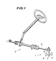
- the present invention relates generally to a rack and pinion steering arrangement and more specifically to such a steering arrangement wherein a sensor is provided therein for sensing a neutral steering position thereof.
- a sensor 1 for sensing the neutral steering position of the steering arrangement 2 has been provided.
- This sensor takes the form of a pair of switches 3,4, located on either side of a knuckle arm 5 operatively interconnecting the steering rod 6 and a road wheel (not shown).
- each of the switches 3,4 is arranged to have a probe member 7 which is contacted by the knuckle arm 5 upon same being moved a predetermined amount from a position wherein the neutral steering condition is maintained.
- the present invention features an arrangement wherein the position of a rack shaft of a rack and pinion steering arrangement is sensed by a switch having a probe which extends into a recess formed in the shaft, when the shaft is in its home or neutral position, and which is depressed downwardly upon the shaft being moved to the left or right of the neutral position.
- the switch may be of the contact type or of a magnetic fluw sensitive type responsive to the depression of the probe.
- the present invention takes the form of a rack and pinion steering arrangement having a rack shaft slidably received in a rack tube and operatively connected with a pinion housed in a gear housing and a sensor for sensing the neutral position of said rack shaft which comprises: means defining a recess in said rack shaft, and a switch having a probe which, in a first position thereof, extends into said recess when said rack shaft is in the neutral position thereof and which, in a second position thereof, is depressed away from said first position by contact with a non-recessed portion of the rack shaft upon said rack shaft being moved axially from said neutral position by a predetermined amount, said switch being arranged to produce an output signal upon said probe being moved from said first position to said second position.
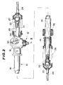
- FIG. 2 shows a partially sectioned view of a rack and steering arrangement 10 in which a neutral steering position sensor 12 according to the present invention, is provided.
- a rack shaft 14 is reciprocatively disposed in a gear housing 16 and rack tube 18 arrangement.
- Ball Socket members 20 are threadedly received in either end of the rack shaft 14, as shown, and arranged to operatively receive therein ball stud members 22 formed or fixedly attached to the ends of steering rods 24.
- corrugated elastomeric boots 26 are provided to cover the exposed ends of the rack shaft 14 and enclose the ball joints defined by the just mentioned ball socket and ball stud arrangements.
- a pinion (not shown) which operatively meshes with the rack 28 formed along one side of the rack shaft 14.
- the pinion is rotatably driven by a shaft 30 which is connectable with a steering column arrangement not shown.
- Suitable elastomeric bushes 32 are arranged to support the rack tube 18 in position on a vehicle chassis (also not shown).
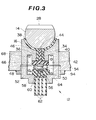
- FIG 3 is cross sectional view taken along section line III-III and shows in detail a first embodiment of a neutral steering position sensor 12 according to the present invention.
- the gear housing 16 is formed with a stepped bore 34 which receives therein, a stem-like extension 36 formed integrally with a resilient elastomeric bush 38 in which the rack shaft 14 is slidably received.
- This bush (38) serves as a reaction member for biasing the rack shaft 14 into firm and constant contact with the pinion.
- a piston-like probe member 42 Slidably disposed in an elongate bore 40 formed in the stem-like extension 36 is a piston-like probe member 42.
- This member is also formed of an elastomeric resin but which in this case is of a relatively hard type.
- the probe member 42 is formed with a rounded tip 44 at one end thereof, which seats in a recess 46 in the rack shaft 14 in a position diametrically opposed the rack 28 when said shaft assumes a neutral steering position (viz., one in which the steerable wheels of the vehicle are oriented in a manner to maintain the vehicle running in a straight line).
- a land 48 is formed at the other end of the probe member 42 and arranged to carry a magnet 50 thereon. This magnet as shown, is arranged juxtapose a Hall-effect switch which is generally denoted by the numeral 52.
- a spring 54 is arranged between the land 48 and a synthetic resin member 56 in which the Hall-effect element 58, lead wires 60 and terminals 62 are enclosed.
- the synthetic resin member 56 is disposed in a cup-like member 64 threadly connected to the gear housing.
- a spring 68 which biases the gear housing and cup-like member apart.
- the cup-like member 64 may be rotated so as to adjust the position of the Hall-effect switch 52 with respect to the magnet 50, when the magnet is in the position shown and/or in the depressed state whichever is deemed the most appropriate, so that upon sufficient movement of the rack shaft 14 to the left or right of the illustrated position, to depress the probe downwardly against the bias of the spring, the magnet 50 is brought into sufficiently close proximity of the Hall-effect switch 52 as to induce the latter to output a signal.
- Figure 4 shows the essential elements of the first embodiment showing the rack shaft 14 located in a neutral steering position and the tip 44 of the probe 42 received in the recess 46 which as shown, has a smoothly curved configuration to facilitate the smooth depression of the probe 42 upon axial movement of the rack shaft 14.
- Figure 5 shows the output of the first embodiment in terms of output voltage and distance. As shown, upon the rack shaft 14 being moved axially by a predetermined distance and the magnet 50 being moved into close proximity of the Hall-effect switch 52, the latter outputs a 5 volt signal (by way of example).
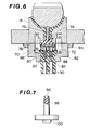
- Figure 6 shows a second embodiment of the present invention.
- the Hall-effect switch 52 is replaced with a more conventional contact type 70.
- a conductive plate 72 is fixedly attached to the lower surface of a probe member 74.
- the probe 74 comprises a metallic pin 76 which is studded into an elastomeric base member 78 on which the conductive plate (viz., movable 72 contact) is fixed.
- the probe 42 of the first embodiment is formed entirely of elastomeric resin to attenuate any possible effect of noise which may be transmitted from the rack shaft 14 and which might interfere with the operation of the magnetic flux density responsive switch employed therein.
- a pair of stationary contacts 80 are mounted in an elastomeric case member 82 and spring loaded via springs 84 so as to be biased to project out of a retaining member 86 fixed to the top of the elastomeric case member 82. Electrically connected to the lower surface of limiting flanges 88 formed at the lower ends of the stationary contacts 80 are lead wires 90. This arrangement of course buffers the switch against damage by repeated contact between the movable and stationary contacts 72, 80.
- the elastomeric case member 82 is retained in a cap member 92 which, as in the first embodiment, is threadedly received in a nut or similar member 94 welded to the gear housing 16.
- the housing per se may be formed with a threaded bore in place of the nut.
- Figure 7 shows an alternative probe design which although shown provided with a magnet 100, may be used in either embodiment given slight design changes.
- This probe is characterized by the provision of a roller bearing type arrangement wherein a ball 96 is rotatably retained at the tip thereof by a sleeve member 98 press fitted onto a reduced diameter portion of the probe. This arrangement reduces the amount of friction produced between the probe and the rack shaft when the shaft is moved from its home or neutral position.
Landscapes
- Engineering & Computer Science (AREA)
- Chemical & Material Sciences (AREA)
- Combustion & Propulsion (AREA)
- Transportation (AREA)
- Mechanical Engineering (AREA)
- Measurement Of Length, Angles, Or The Like Using Electric Or Magnetic Means (AREA)
Applications Claiming Priority (2)
| Application Number | Priority Date | Filing Date | Title |
|---|---|---|---|
| JP51874/82 | 1982-03-30 | ||
| JP5187482A JPS58170665A (ja) | 1982-03-30 | 1982-03-30 | ラツクアンドピニオン式ステアリング装置 |
Publications (2)
| Publication Number | Publication Date |
|---|---|
| EP0090697A2 true EP0090697A2 (de) | 1983-10-05 |
| EP0090697A3 EP0090697A3 (de) | 1984-08-29 |
Family
ID=12899024
Family Applications (1)
| Application Number | Title | Priority Date | Filing Date |
|---|---|---|---|
| EP83400511A Withdrawn EP0090697A3 (de) | 1982-03-30 | 1983-03-11 | Zahnstangenlenkungseinrichtung mit neutralem Stellungsanweiser |
Country Status (2)
| Country | Link |
|---|---|
| EP (1) | EP0090697A3 (de) |
| JP (1) | JPS58170665A (de) |
Cited By (7)
| Publication number | Priority date | Publication date | Assignee | Title |
|---|---|---|---|---|
| US4651841A (en) * | 1984-02-15 | 1987-03-24 | Trw Cam Gears Limited | Power assistance steering system for a vehicle |
| US4785901A (en) * | 1986-07-17 | 1988-11-22 | Tokai Trw & Co. Ltd. | Rack and pinion steering gear with electric power assistance |
| EP0410583A1 (de) * | 1989-07-24 | 1991-01-30 | General Motors Corporation | Berührungsloses Positionsdetektionsgerät für ein Kraftfahrzeuglenkgetriebe |
| EP0376512A3 (de) * | 1988-12-27 | 1992-11-19 | Ford Motor Company Limited | Fahzeuglenksystem |
| WO2016198518A1 (de) * | 2015-06-09 | 2016-12-15 | Tedrive Steering Systems Gmbh | Zahnstangenlenkgehäuse mit integriertem gleitstein |
| DE102019120586A1 (de) * | 2019-07-30 | 2021-02-04 | Bayerische Motoren Werke Aktiengesellschaft | Sensorhalter, Sensoranordnung, Messanordnung und Verfahren zum Messen eines Druckstückspiels in einem Zahnstangenlenkgetriebe |
| CN113895507A (zh) * | 2021-09-30 | 2022-01-07 | 中汽创智科技有限公司 | 一种压紧装置及助力转向系统 |
Family Cites Families (7)
| Publication number | Priority date | Publication date | Assignee | Title |
|---|---|---|---|---|
| DE1159286B (de) * | 1958-07-18 | 1963-12-12 | Zahnradfabrik Friedrichshafen | Durch Hilfskraft unterstuetzte Lenkeinrichtung, insbesondere fuer Kraftfahrzeuge |
| US3924705A (en) * | 1971-12-08 | 1975-12-09 | Aisin Seiki | Power steering mechanism |
| JPS579987B2 (de) * | 1975-02-06 | 1982-02-24 | ||
| JPS587504B2 (ja) * | 1976-02-26 | 1983-02-10 | アイシン精機株式会社 | 動力舵取装置の操舵角制限装置 |
| DE2839121A1 (de) * | 1978-09-08 | 1980-03-27 | Bosch Gmbh Robert | Elektro-hydraulische servolenkung |
| DE2900510A1 (de) * | 1979-01-08 | 1980-07-17 | Bosch Gmbh Robert | Servolenkung fuer kraftfahrzeuge |
| DE3006297A1 (de) * | 1980-02-20 | 1981-08-27 | Robert Bosch Gmbh, 7000 Stuttgart | Hydraulische lenkvorrichtung |
-
1982
- 1982-03-30 JP JP5187482A patent/JPS58170665A/ja active Granted
-
1983
- 1983-03-11 EP EP83400511A patent/EP0090697A3/de not_active Withdrawn
Cited By (7)
| Publication number | Priority date | Publication date | Assignee | Title |
|---|---|---|---|---|
| US4651841A (en) * | 1984-02-15 | 1987-03-24 | Trw Cam Gears Limited | Power assistance steering system for a vehicle |
| US4785901A (en) * | 1986-07-17 | 1988-11-22 | Tokai Trw & Co. Ltd. | Rack and pinion steering gear with electric power assistance |
| EP0376512A3 (de) * | 1988-12-27 | 1992-11-19 | Ford Motor Company Limited | Fahzeuglenksystem |
| EP0410583A1 (de) * | 1989-07-24 | 1991-01-30 | General Motors Corporation | Berührungsloses Positionsdetektionsgerät für ein Kraftfahrzeuglenkgetriebe |
| WO2016198518A1 (de) * | 2015-06-09 | 2016-12-15 | Tedrive Steering Systems Gmbh | Zahnstangenlenkgehäuse mit integriertem gleitstein |
| DE102019120586A1 (de) * | 2019-07-30 | 2021-02-04 | Bayerische Motoren Werke Aktiengesellschaft | Sensorhalter, Sensoranordnung, Messanordnung und Verfahren zum Messen eines Druckstückspiels in einem Zahnstangenlenkgetriebe |
| CN113895507A (zh) * | 2021-09-30 | 2022-01-07 | 中汽创智科技有限公司 | 一种压紧装置及助力转向系统 |
Also Published As
| Publication number | Publication date |
|---|---|
| EP0090697A3 (de) | 1984-08-29 |
| JPS58170665A (ja) | 1983-10-07 |
| JPS624268B2 (de) | 1987-01-29 |
Similar Documents
| Publication | Publication Date | Title |
|---|---|---|
| US3408124A (en) | Idler arm construction | |
| US4976166A (en) | Electronic foot pedal | |
| US7404342B2 (en) | Accelerator pedal for motorized vehicle | |
| US5331124A (en) | Wireless floating horn switch | |
| EP0090697A2 (de) | Zahnstangenlenkungseinrichtung mit neutralem Stellungsanweiser | |
| US5430334A (en) | Impact sensor for vehicle safety restraint system | |
| CN118742468A (zh) | 一种踏板垫组件 | |
| EP0713637B1 (de) | Zugkraftsensorgerät | |
| ATE42842T1 (de) | Hebelsteuervorrichtung. | |
| US3955636A (en) | Weighing apparatus for truck and vehicle loads | |
| US2809049A (en) | Steering gear idler arm assemblies | |
| JP4428825B2 (ja) | 電動自転車のトルク検出装置およびそれを用いた電動自転車 | |
| CA1055064A (en) | Resilient steering stabilizer | |
| DE10341277A1 (de) | Pedal-Vorrichtung für Kraftfahrzeuge | |
| CA1140650A (en) | Variable inductance transducers | |
| US4929805A (en) | Gas damped deceleration switch | |
| US4885439A (en) | Gas damped deceleration switch | |
| JP4729507B2 (ja) | 変位検出装置 | |
| JP2004340966A (ja) | 回転センサおよび回転センサ用の連結部材 | |
| US2790052A (en) | Precision resistance devices | |
| KR20240174198A (ko) | 자동차 조향장치 | |
| US6181240B1 (en) | Tire-safety sensing device | |
| US3160014A (en) | Pressure transducer | |
| US2834844A (en) | Tire and wheel alarm | |
| KR910007592Y1 (ko) | 스티어링 토크 검출기 |
Legal Events
| Date | Code | Title | Description |
|---|---|---|---|
| PUAI | Public reference made under article 153(3) epc to a published international application that has entered the european phase |
Free format text: ORIGINAL CODE: 0009012 |
|
| 17P | Request for examination filed |
Effective date: 19830317 |
|
| AK | Designated contracting states |
Designated state(s): DE FR GB Kind code of ref document: A2 Designated state(s): DE FR GB |
|
| PUAL | Search report despatched |
Free format text: ORIGINAL CODE: 0009013 |
|
| AK | Designated contracting states |
Designated state(s): DE FR GB Kind code of ref document: A3 Designated state(s): DE FR GB |
|
| STAA | Information on the status of an ep patent application or granted ep patent |
Free format text: STATUS: THE APPLICATION HAS BEEN WITHDRAWN |
|
| 18W | Application withdrawn |
Withdrawal date: 19841008 |
|
| RIN1 | Information on inventor provided before grant (corrected) |
Inventor name: YAMAGUCHI, HIROTSUGU Inventor name: SASAKI, SHUICHI Inventor name: AOYAMA, YUTAKA Inventor name: FUKINO, MASATO Inventor name: YANAI, TOKIYOSHI |