EP0090655A1 - Treatment of exhaust gases - Google Patents
Treatment of exhaust gases Download PDFInfo
- Publication number
- EP0090655A1 EP0090655A1 EP83301779A EP83301779A EP0090655A1 EP 0090655 A1 EP0090655 A1 EP 0090655A1 EP 83301779 A EP83301779 A EP 83301779A EP 83301779 A EP83301779 A EP 83301779A EP 0090655 A1 EP0090655 A1 EP 0090655A1
- Authority
- EP
- European Patent Office
- Prior art keywords
- duct
- liquid
- gases
- exhaust gases
- stack
- Prior art date
- Legal status (The legal status is an assumption and is not a legal conclusion. Google has not performed a legal analysis and makes no representation as to the accuracy of the status listed.)
- Withdrawn
Links
Images

Classifications
-
- B—PERFORMING OPERATIONS; TRANSPORTING
- B01—PHYSICAL OR CHEMICAL PROCESSES OR APPARATUS IN GENERAL
- B01D—SEPARATION
- B01D47/00—Separating dispersed particles from gases, air or vapours by liquid as separating agent
- B01D47/06—Spray cleaning
Definitions
- the present invention relates to the treatment of exhaust gases, especially to treatment of exhaust gases in vertical columns.
- the gas may contain desirable by-products.
- the gases which may be at an elevated temperature, are generally vented to the atmosphere by means of a vertical exhaust stack. However, it may be desirable to cool the gases before they leave the stack, to remove components from the gas and/or so that the gas leaving the stack is nearer the ambient atmosphere temperature, or so that the heat from the gas may be used.
- This may be achieved by spraying relatively cool liquid into an upper part of the stack, so that the droplets of liquid contact the exhaust gases and a heat exchange takes place, so that the gases are cooled, and the liquid heated.
- the spray is situated in the upper part of the stack so that the liquid can travel virtually the whole length of the stack in order to obtain as high a level of heat exchange as possible.
- the liquid may be used as a heat exchange medium or directly used in a further process if required.
- the use of small droplets of liquid in the form of a spray has been found to be more efficient for the transfer of heat from the gases to the liquid than the use of cooling liquid in bulk.
- a method of treatment of exhaust gases by contacting said gases with a liquid comprising passing said exhaust gases up an upwardly and extending duct, / passing the liquid down said duct in the form of a spray or mist, said liquid entering the duct at a plurality of vertically spaced apart positions along the duct.
- said duct is an exhaust stack.
- said duct is a vessel within which condensation of vapour carried by the warm gases is to be condensed.
- said vertically separated entrance points are supplied with liquid from a common liquid supply line.
- the liquid is supplied to the uppermost entrance point, caught further down the duct and then passed through the vertically adjacent entrance point,the cycle being repeated along the length of the duct as many times as required.
- the liquid is water.
- the efficiency of spray contacting systems decrease fairly rapidly with the distance of the liquid from the spray producing means. This may possibly be because of agglomeration of a plurality cf water droplets forming a larger droplet which is a less efficient heat transfer medium, or for other reasons. Therefore, the present invention provides a method for achieving more efficient heat transfer from a gas to the liquid by causing the liquid to be passed through a plurality of, for instance, spray heads at vertically spaced positions along the duct to minimise the loss of efficiency of known systems.
- the present invention also provides apparatus for the treatment of exhaust gases by contacting said gases with a liquid, the apparatus comprising an upwardly extending duct along which the exhaust gases may be passed, and means for spraying a liquid down said duct, said means being disposed at vertically separated positions along the duct.
- the present invention may be advantageously used wherever conventional sprays are at present used, for instance, in the cooling of exhaust gases from immersed combustion heaters before the venting of said gases to the atmosphere, or in direct contact heat exchanges.
- apparatus in accordance with the present invention comprises the exhaust stack 3 of, for example, immersed combustion apparatus.
- the exhaust gases are delivered to the bottom of the exhaust stack by means of an inlet pipe 5.
- the gases then rise up the stack 3 and eventually are vented to the atmosphere through an opening at the top of the stack 13.
- a supply pipe 15 enters the stack 3 near the top thereof and ends in a plurality of sprayer heads 17 arranged so as to spray the liquid down the duct.
- the liquid is water, although in alternative embodiments it may be any suitable liquid.
- the water is of a lower temperature than that of the exhaust gases and so coming into contact with the gases in the form of a spray has the effect of both cooling the gases and heating the water.
- the heat exchange takes place most efficiently within a relatively short distance of the sprayer heads 17. Therefore, the water spray is defected by means of a conical deflector 19 whose axis lies on the central axis of the stack 3, into a substantially annular container fixed to the inner surface of the stack 3.
- the water collected in the annular container 21 is then removed by means of pipe-line 23 by a pump (not shown) and then re-enters the stack 3 to be sprayed again through spray heads 25.
- the spray is again deflected by a deflector 27 into an annular container 29, whence it is removed by pipe-line 31 and supplied under pressure to the third set of sprayer heads 33.
- the warmed liquid is then removed by means of outlet pipe 7 and pump 9 and passed through a suitable heat exchanger 11.
- the heat so produced may be used for any suitable purpose such as, the heating of liquid natural gas or other cryogenic fluids or the heating of water for use in a central heating system.
- the water having passed through heat exchange means 11 is substantially cooler than that at the bottom of the stack 3 and also cooler than the exhaust gases.
- the distance between the adjacent sets of sprayer heads should be as close as possible, but that a suitable distance is approximately 12 inches.
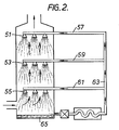
- FIG. 2 of the present invention An alternative embodiment of the present invention, diagramatically represented in Figure 2 of the present invention, is essentially similar to the embodiment described with reference to Figure 1, with the exception that each vertically separated group of sprayer heads 51, 53 and 55, is supplied by pipes 57, 59 and 61 respecitvely , from a common supply catching means. line 63. This obviates the need for the deflectors and
- the water, together with possible components of the gases extracted by condensation, is removed from the bottom 65 of the stack 67 and processed as required, for instance, to extract the components, or to extract the heat from the water so that it can be recycled into supply line 63.
- Apparatus in accordance with the present invention thus has several advantages over comparable known systems, in that there is a relatively low pressure required to pass the gas up the stack against the flow of the liquid, and there is a higher degree of contact between the liquid and the gas leading, in the embodiment described herein, to a relatively large increase in temperature of the water It is therefore possible for a system as including apparatus in accordance with the present invention to be substantially more efficient than conventional systems.
Abstract
A method and apparatus for the treatment of relevant gases from industrial processes by contacting the gases with a liquid, preferably water, the method involving passing said gases up an upwardly extending duct (3), and passing the liquid down said duct in the form of a spray or mist, the liquid entering the duct at a plurality of vertically spaced apart portions along the duct (17, 25, 33).
Description
- The present invention relates to the treatment of exhaust gases, especially to treatment of exhaust gases in vertical columns.
- There are several industrial processes, where an exhaust gas is produced. The gas, or gases, may contain desirable by-products. The gases, which may be at an elevated temperature, are generally vented to the atmosphere by means of a vertical exhaust stack. However, it may be desirable to cool the gases before they leave the stack, to remove components from the gas and/or so that the gas leaving the stack is nearer the ambient atmosphere temperature, or so that the heat from the gas may be used.
- This may be achieved by spraying relatively cool liquid into an upper part of the stack, so that the droplets of liquid contact the exhaust gases and a heat exchange takes place, so that the gases are cooled, and the liquid heated.
- The spray is situated in the upper part of the stack so that the liquid can travel virtually the whole length of the stack in order to obtain as high a level of heat exchange as possible.
- At the bottom of the stack the liquid, together with any valuable by products condensed from the gases, may be used as a heat exchange medium or directly used in a further process if required. The use of small droplets of liquid in the form of a spray has been found to be more efficient for the transfer of heat from the gases to the liquid than the use of cooling liquid in bulk.
- According to the present invention there is provided a method of treatment of exhaust gases by contacting said gases with a liquid, the method comprising passing said exhaust gases up an upwardly and extending duct,/passing the liquid down said duct in the form of a spray or mist, said liquid entering the duct at a plurality of vertically spaced apart positions along the duct.
- Preferably said duct is an exhaust stack. Alternatively said duct is a vessel within which condensation of vapour carried by the warm gases is to be condensed.
- Preferably said vertically separated entrance points are supplied with liquid from a common liquid supply line. Alternatively, the liquid is supplied to the uppermost entrance point, caught further down the duct and then passed through the vertically adjacent entrance point,the cycle being repeated along the length of the duct as many times as required.
- Preferably the liquid is water.
- It has now been found that the efficiency of spray contacting systems decrease fairly rapidly with the distance of the liquid from the spray producing means. This may possibly be because of agglomeration of a plurality cf water droplets forming a larger droplet which is a less efficient heat transfer medium, or for other reasons. Therefore, the present invention provides a method for achieving more efficient heat transfer from a gas to the liquid by causing the liquid to be passed through a plurality of, for instance, spray heads at vertically spaced positions along the duct to minimise the loss of efficiency of known systems.
- The present invention also provides apparatus for the treatment of exhaust gases by contacting said gases with a liquid, the apparatus comprising an upwardly extending duct along which the exhaust gases may be passed, and means for spraying a liquid down said duct, said means being disposed at vertically separated positions along the duct.
- The present invention may be advantageously used wherever conventional sprays are at present used, for instance, in the cooling of exhaust gases from immersed combustion heaters before the venting of said gases to the atmosphere, or in direct contact heat exchanges.
- Embodiments of the present invention will now be described, by way of example only, and with reference to the accompanying drawings, in which:-
- Figure 1 is a diagrammatic representation of a first embodiment of the present invention; and
- Figure 2 is a diagrammatic representation of a second embodiment of the present invention.
- Referring to Figure 1 of the accompanying drawings, apparatus in accordance with the present invention, indicated generally by 1, comprises the
exhaust stack 3 of, for example, immersed combustion apparatus. The exhaust gases are delivered to the bottom of the exhaust stack by means of an inlet pipe 5. The gases then rise up thestack 3 and eventually are vented to the atmosphere through an opening at the top of thestack 13. - However it may be desired to increase the efficiency of the entire operating system by removing as much as possible of the heat from the exhaust gases before venting them to the atmosphere. Additionally, it may be desired to remove vapourised liquids from the warm gases by means of condensation within the stack. Accordingly, a
supply pipe 15 enters thestack 3 near the top thereof and ends in a plurality ofsprayer heads 17 arranged so as to spray the liquid down the duct. In this embodiment the liquid is water, although in alternative embodiments it may be any suitable liquid. The water is of a lower temperature than that of the exhaust gases and so coming into contact with the gases in the form of a spray has the effect of both cooling the gases and heating the water. However, the heat exchange takes place most efficiently within a relatively short distance of thesprayer heads 17. Therefore, the water spray is defected by means of aconical deflector 19 whose axis lies on the central axis of thestack 3, into a substantially annular container fixed to the inner surface of thestack 3. - The water collected in the annular container 21 is then removed by means of pipe-line 23 by a pump (not shown) and then re-enters the
stack 3 to be sprayed again throughspray heads 25. The spray is again deflected by adeflector 27 into anannular container 29, whence it is removed by pipe-line 31 and supplied under pressure to the third set ofsprayer heads 33. - At the bottom of the
stack 3 the water, together with any liquids condensed from vapour carried by the exhaust gases collects in the bottom of thest-ack 35. - The warmed liquid is then removed by means of
outlet pipe 7 andpump 9 and passed through asuitable heat exchanger 11. The heat so produced may be used for any suitable purpose such as, the heating of liquid natural gas or other cryogenic fluids or the heating of water for use in a central heating system. The water having passed through heat exchange means 11 is substantially cooler than that at the bottom of thestack 3 and also cooler than the exhaust gases. - It is therefore passed upwardly along pipe-
line 15 and re-enters thestack 3 so as to be sprayed from thefirst sprayer head 17 at the top of thestack 3. - It has been found that the distance between the adjacent sets of sprayer heads should be as close as possible, but that a suitable distance is approximately 12 inches.
- An alternative embodiment of the present invention, diagramatically represented in Figure 2 of the present invention, is essentially similar to the embodiment described with reference to Figure 1, with the exception that each vertically separated group of
sprayer heads line 63. This obviates the need for the deflectors and - The water, together with possible components of the gases extracted by condensation, is removed from the
bottom 65 of the stack 67 and processed as required, for instance, to extract the components, or to extract the heat from the water so that it can be recycled intosupply line 63. - Apparatus in accordance with the present invention thus has several advantages over comparable known systems, in that there is a relatively low pressure required to pass the gas up the stack against the flow of the liquid, and there is a higher degree of contact between the liquid and the gas leading, in the embodiment described herein, to a relatively large increase in temperature of the water It is therefore possible for a system as including apparatus in accordance with the present invention to be substantially more efficient than conventional systems.
Claims (5)
1. A method of treatment of exhaust gases by contacting said gases with a liquid characterised in that the method comprises passing said exhaust gases up an upwardly extending duct, and passing the liquid down said duct in the form of a spray or mist, said liquid entering the duct at a plurality of vertically spaced apart positions along the duct.
2. A method according to claim 1 characterised in that said duct is an exhaust stack.
3. A method according to claim 1 or claim 2 characterised in that said vertically separated entrance points are supplied with liquid from a common liquid supply line.
4. A method according to claim 1 or claim 2 characterised in that the liquid is supplied to the uppermost entrance point, collected further down the duct and then passed through the vertically adjacent entrance point, the cycle being repeated along the length of the duct as many times as required.
5. Apparatus for the treatment of exhaust gases by contacting said gases with a liquid characterised in that the apparatus comprises an upwardly extending duct along which the exhaust gases may be passed, and means for spraying a liquid down said duct, said means being disposed at vertically separated positions along the duct.
Applications Claiming Priority (2)
| Application Number | Priority Date | Filing Date | Title |
|---|---|---|---|
| GB8209345 | 1982-03-30 | ||
| GB8209345 | 1982-03-30 |
Publications (1)
| Publication Number | Publication Date |
|---|---|
| EP0090655A1 true EP0090655A1 (en) | 1983-10-05 |
Family
ID=10529402
Family Applications (1)
| Application Number | Title | Priority Date | Filing Date |
|---|---|---|---|
| EP83301779A Withdrawn EP0090655A1 (en) | 1982-03-30 | 1983-03-30 | Treatment of exhaust gases |
Country Status (1)
| Country | Link |
|---|---|
| EP (1) | EP0090655A1 (en) |
Cited By (5)
| Publication number | Priority date | Publication date | Assignee | Title |
|---|---|---|---|---|
| EP0276035A1 (en) * | 1987-01-20 | 1988-07-27 | Persluchtcentrale Nederland B.V. | Installation for cleaning surfaces |
| WO1993018348A1 (en) * | 1992-03-05 | 1993-09-16 | Lucien Fauteux | Fume purification system |
| EP1447123A1 (en) * | 2003-02-12 | 2004-08-18 | FOIDL, Leonhard | Device for cleaning of exhaust gasses containing pollutants |
| GB2402085A (en) * | 2002-03-01 | 2004-12-01 | Oiko Group Ltd | Device for removing pollutants from exhaust gases |
| GB2402086A (en) * | 2002-03-01 | 2004-12-01 | Oiko Group Ltd | Device for removing pollutants from exhaust gases |
Citations (7)
| Publication number | Priority date | Publication date | Assignee | Title |
|---|---|---|---|---|
| US2972393A (en) * | 1959-03-25 | 1961-02-21 | Allied Chem | Process for treating coke oven gas |
| GB1082511A (en) * | 1963-01-29 | 1967-09-06 | Ass Elect Ind | Improvements relating to methods of and apparatus for the cooling of hot gases by direct contact with water |
| US3532595A (en) * | 1965-06-02 | 1970-10-06 | Mo Och Domsjoe Ab | Method for producing high-grade hot water by means of combustion gases from sulphite or sulphate cellulose processes and apparatus for carrying out the method |
| US3895926A (en) * | 1973-05-02 | 1975-07-22 | Bernard J Lerner | Method for treating a gas |
| DE2538187A1 (en) * | 1974-09-03 | 1976-03-11 | Yoshio Mitani | Dust removal from waste gases by wet scrubbing - using coagulant to precipitate dust from recirculated scrubbing liquor |
| DE2556304A1 (en) * | 1975-12-13 | 1977-06-23 | Heinz Hoelter | Heat recovery in coal gasification process - with a heat exchange element placed in the liq. circulation of a gas washer |
| FR2484070A1 (en) * | 1980-06-04 | 1981-12-11 | Ind Chauffage | Heat exchanger for condenser - has sprayer at top of cylinder and condensing plates with water sump |
-
1983
- 1983-03-30 EP EP83301779A patent/EP0090655A1/en not_active Withdrawn
Patent Citations (7)
| Publication number | Priority date | Publication date | Assignee | Title |
|---|---|---|---|---|
| US2972393A (en) * | 1959-03-25 | 1961-02-21 | Allied Chem | Process for treating coke oven gas |
| GB1082511A (en) * | 1963-01-29 | 1967-09-06 | Ass Elect Ind | Improvements relating to methods of and apparatus for the cooling of hot gases by direct contact with water |
| US3532595A (en) * | 1965-06-02 | 1970-10-06 | Mo Och Domsjoe Ab | Method for producing high-grade hot water by means of combustion gases from sulphite or sulphate cellulose processes and apparatus for carrying out the method |
| US3895926A (en) * | 1973-05-02 | 1975-07-22 | Bernard J Lerner | Method for treating a gas |
| DE2538187A1 (en) * | 1974-09-03 | 1976-03-11 | Yoshio Mitani | Dust removal from waste gases by wet scrubbing - using coagulant to precipitate dust from recirculated scrubbing liquor |
| DE2556304A1 (en) * | 1975-12-13 | 1977-06-23 | Heinz Hoelter | Heat recovery in coal gasification process - with a heat exchange element placed in the liq. circulation of a gas washer |
| FR2484070A1 (en) * | 1980-06-04 | 1981-12-11 | Ind Chauffage | Heat exchanger for condenser - has sprayer at top of cylinder and condensing plates with water sump |
Cited By (7)
| Publication number | Priority date | Publication date | Assignee | Title |
|---|---|---|---|---|
| EP0276035A1 (en) * | 1987-01-20 | 1988-07-27 | Persluchtcentrale Nederland B.V. | Installation for cleaning surfaces |
| WO1993018348A1 (en) * | 1992-03-05 | 1993-09-16 | Lucien Fauteux | Fume purification system |
| GB2402085A (en) * | 2002-03-01 | 2004-12-01 | Oiko Group Ltd | Device for removing pollutants from exhaust gases |
| GB2402086A (en) * | 2002-03-01 | 2004-12-01 | Oiko Group Ltd | Device for removing pollutants from exhaust gases |
| GB2402086B (en) * | 2002-03-01 | 2005-08-17 | Oiko Group Ltd | Device and method for removing pollutants from exhaust gases |
| EP1447123A1 (en) * | 2003-02-12 | 2004-08-18 | FOIDL, Leonhard | Device for cleaning of exhaust gasses containing pollutants |
| AT412261B (en) * | 2003-02-12 | 2004-12-27 | Foidl Leonhard | DEVICE FOR PURIFYING COMBUSTION GASES CONTAINING POLLUTANTS |
Similar Documents
| Publication | Publication Date | Title |
|---|---|---|
| US3473298A (en) | Moisture content and combustion product removal apparatus for exhaust gases | |
| US3834133A (en) | Direct contact condenser having an air removal system | |
| US6019819A (en) | Apparatus and method for extracting heat from contaminated waste steam | |
| CA2394011A1 (en) | Fluidized spray tower | |
| CA1260382A (en) | Method and apparatus to convert a long tube vertical evaporator to a falling film evaporator | |
| CN101641462A (en) | Flue gas cooling and cleaning system | |
| GB1589420A (en) | Condenser tube bundle | |
| US4969507A (en) | Integral blow down concentrator with air-cooled surface condenser | |
| US1233119A (en) | System and apparatus for spraying in cooling-ponds and the like. | |
| EP0090655A1 (en) | Treatment of exhaust gases | |
| US3063681A (en) | Transfer of heat from superheated vapor in a condensing heat exchanger | |
| US4615770A (en) | Distillation column and process | |
| GB2094951A (en) | Method for the mass conversion of a liquid flow into a steam flow and apparatus therefor | |
| CN1034633C (en) | Reduced pressure heat treating device | |
| US2077427A (en) | Gas scrubber | |
| US3622466A (en) | Method of recovering water-free fatty acid distillates by selective condensation | |
| JPH07502170A (en) | Downstream heating equipment | |
| CN1195567C (en) | An apparatus for evaporative cooling of a liquid form product | |
| JP3170669B2 (en) | Heating and cooling device | |
| JP2857204B2 (en) | Liquid outlet for gas / liquid contact tower | |
| MY115736A (en) | Vertical fluid dynamic cooling tower | |
| EP0112041B1 (en) | Method and apparatus for the absorption of a gas in a liquid and their use in energy conversion cycles | |
| US6619042B2 (en) | Deaeration of makeup water in a steam surface condenser | |
| SE514866C2 (en) | Device for cooling gases | |
| EP0067005A1 (en) | Fog prevention |
Legal Events
| Date | Code | Title | Description |
|---|---|---|---|
| PUAI | Public reference made under article 153(3) epc to a published international application that has entered the european phase |
Free format text: ORIGINAL CODE: 0009012 |
|
| AK | Designated contracting states |
Designated state(s): AT BE CH DE FR GB IT LI LU NL SE Kind code of ref document: A1 Designated state(s): AT BE CH DE FR GB IT LI LU NL SE |
|
| 17P | Request for examination filed |
Effective date: 19840403 |
|
| STAA | Information on the status of an ep patent application or granted ep patent |
Free format text: STATUS: THE APPLICATION IS DEEMED TO BE WITHDRAWN |
|
| 18D | Application deemed to be withdrawn |
Effective date: 19850624 |
|
| RIN1 | Information on inventor provided before grant (corrected) |
Inventor name: THURLEY, JOHN Inventor name: ARNOLD, GERALD DESMOND |