EP0090573A1 - Bandkassette - Google Patents
Bandkassette Download PDFInfo
- Publication number
- EP0090573A1 EP0090573A1 EP83301574A EP83301574A EP0090573A1 EP 0090573 A1 EP0090573 A1 EP 0090573A1 EP 83301574 A EP83301574 A EP 83301574A EP 83301574 A EP83301574 A EP 83301574A EP 0090573 A1 EP0090573 A1 EP 0090573A1
- Authority
- EP
- European Patent Office
- Prior art keywords
- cover
- front cover
- locking piece
- tape cassette
- tape
- Prior art date
- Legal status (The legal status is an assumption and is not a legal conclusion. Google has not performed a legal analysis and makes no representation as to the accuracy of the status listed.)
- Granted
Links
- 230000003287 optical effect Effects 0.000 claims abstract description 46
- 230000000717 retained effect Effects 0.000 claims description 9
- 239000000428 dust Substances 0.000 abstract description 8
- 230000009471 action Effects 0.000 description 11
- 238000003780 insertion Methods 0.000 description 3
- 230000037431 insertion Effects 0.000 description 3
- 238000010276 construction Methods 0.000 description 2
- 238000000034 method Methods 0.000 description 2
- 239000004925 Acrylic resin Substances 0.000 description 1
- 229920000178 Acrylic resin Polymers 0.000 description 1
- 239000000470 constituent Substances 0.000 description 1
- 230000008094 contradictory effect Effects 0.000 description 1
- 230000014759 maintenance of location Effects 0.000 description 1
- 239000007769 metal material Substances 0.000 description 1
- 238000012986 modification Methods 0.000 description 1
- 230000004048 modification Effects 0.000 description 1
- 230000008569 process Effects 0.000 description 1
Images


Classifications
-
- H—ELECTRICITY
- H01—ELECTRIC ELEMENTS
- H01J—ELECTRIC DISCHARGE TUBES OR DISCHARGE LAMPS
- H01J1/00—Details of electrodes, of magnetic control means, of screens, or of the mounting or spacing thereof, common to two or more basic types of discharge tubes or lamps
- H01J1/02—Main electrodes
- H01J1/13—Solid thermionic cathodes
- H01J1/15—Cathodes heated directly by an electric current
-
- G—PHYSICS
- G11—INFORMATION STORAGE
- G11B—INFORMATION STORAGE BASED ON RELATIVE MOVEMENT BETWEEN RECORD CARRIER AND TRANSDUCER
- G11B23/00—Record carriers not specific to the method of recording or reproducing; Accessories, e.g. containers, specially adapted for co-operation with the recording or reproducing apparatus ; Intermediate mediums; Apparatus or processes specially adapted for their manufacture
- G11B23/02—Containers; Storing means both adapted to cooperate with the recording or reproducing means
- G11B23/04—Magazines; Cassettes for webs or filaments
- G11B23/08—Magazines; Cassettes for webs or filaments for housing webs or filaments having two distinct ends
- G11B23/087—Magazines; Cassettes for webs or filaments for housing webs or filaments having two distinct ends using two different reels or cores
- G11B23/08707—Details
- G11B23/08735—Covers
-
- G—PHYSICS
- G11—INFORMATION STORAGE
- G11B—INFORMATION STORAGE BASED ON RELATIVE MOVEMENT BETWEEN RECORD CARRIER AND TRANSDUCER
- G11B23/00—Record carriers not specific to the method of recording or reproducing; Accessories, e.g. containers, specially adapted for co-operation with the recording or reproducing apparatus ; Intermediate mediums; Apparatus or processes specially adapted for their manufacture
- G11B23/02—Containers; Storing means both adapted to cooperate with the recording or reproducing means
- G11B23/04—Magazines; Cassettes for webs or filaments
- G11B23/08—Magazines; Cassettes for webs or filaments for housing webs or filaments having two distinct ends
- G11B23/087—Magazines; Cassettes for webs or filaments for housing webs or filaments having two distinct ends using two different reels or cores
Definitions
- the present invention relates to a tape cassette for use in audio, video and data recorders, and more particularly, to a tape cassette having a front cover for covering the tape stretched along openings formed in the front surface of a casette case and a cover-locking piece for preventing the front cover from opening when the tape cassette is not in use.
- Examples of the conventional tape cassette of this type include ones employed for known VHS or 0 system VTRs. Both of these tape cassettes have a front-cover spring for urging the front cover to pivot in the direction for covering the tape stretched along the opening formed in the front surface thereof.
- a tape cassette is provided with a cover-locking piece adapted to prevent the front cover from opening when the tape cassette is not in use and to pivot in the widthwise direction of the tape cassette, and a locking spring for engaging the cover-locking piece with the front cover and urging the cover-locking piece in the direction for preventing the front cover from opening.
- an optical path aperture in a side surface portion of the tape cassette in case of employing the system for detecting the light transmissible leading and trailing ends of a tape having a transparent leader tape attached to each of the leading and trailing ends thereof, as is employed in, for example, a VHS system VTR in which either one of light-emitting and light-receiving detecting means is entered into the cassette through the bottom surface thereof while the other is disposed outside the tape cassette in opposite to the former through the tape within the tape cassette.
- the optical path aperture is generally disposed at a side plate portin of the tape cassette case and can be covered, when the tape cassette is not in use, by the side plate portion of the front cover pivotally supported at case side plate portions.
- the side plate portion will cover the optical path aperture at a predetermined distance therebetween in the case of a compact tape cassette which needs to provide the front-cover spring for urging the front cover and the cover lock for preventing the front cover from opening in the space defined between the side plate portion of the front cover and the case side plate portion which are a predetermined distance away from each other. It is contradictory, since the compact tape cassette is desirable to make the widthwise dimension thereof as small as possible.
- the optical path aperture similarly to the other openings of the tape cassete, causes dropouts since, dust enteing through the openings, adheres to the tape within the tape cassette. This problem is more serious, particularly, in the case of a portable tape cassette for short-wavelength and high-density recording since, in such a case, the tape cassette will be possibly carried in a pocket of clothing or the like.
- a tape cassette comprising:
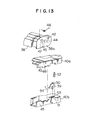
- FIG. 1 is a partly cutway schematic plan view of a tape cassette in accordance with a first preferred embodiment of the invention.
- a tape 4 wound on a pair of reels 2, 3 and stretched along an opening formed in the front surface of a cassette case 1 is covered, when the tape cassette is not in use, by a front cover 7 pivotally supported by side surfaces of the cassette case 1 through pivot portions 5, 6.
- a space 11 is defined by a side plate portion 8 of the front cover 7, a case side plate portion 9 of the cassette case 1 and a case outer plate portion 10 which are a predetermined distance away from each other.
- a front-cover spring 12 for pivotally urging the front cover 7 and a cover-locking piece 13, together with a locking spring 14 as well as first and second projections 23, 22 as described hereinafter (see Figs. 3 and 4).
- an opening 36 for allowing a light-emitting element or light-receiving detecting means (which are not shown) to enter the inside of the cassette case 1 is provided in a substantially central portion of the cassette case 1.
- an optical path aperture 33 is opened in the case side plate portion 9, as shown in Fig. 2 which is a perspective view, so as to form an optical path shown by a one-dot-and-dash line through the tape inside the cassette case 1.
- a transparent leader tape (not shown) attached to each of the leading and trailing end of the tape 4 is detected by the light-emitting element and the light-receiving detecting means (now shown) which are adapted to be positioned in the opening 36 and the outside the cassette case 1, or vice versa, respectively, thereby the traveling mode of the tape 4 is controlled.
- a transparent collar (not shown) made of acrylic resin or the like is fitted in the opening 36 in correspondence with the height of the optical path inside the cassette case 1.
- the upper half 1 is constituted by an upper half la and a lower half lb.
- the lower half lb has recesses 15 formed in the case side plate portion 9 and the case outer plate portion 10, respectively, for supporting the cover-locking piece 13 pivotally in a plane thicknesswise of the tape cassette.
- the upper half 1 on the other hand, has a recess 16 formed in the side plate portion 9 for pivotally supporting the front cover 7. As shown in Fig. 2, the recesses and projections are arranged so as to face each other at the positions corresponding to each other in order to pivotally clamp the above-mentioned respective members.
- the front cover 7 is provided with a notch 19 for allowing the entry of a cover-opening member 17 (Fig. 7), described later, and a notch 21 for partly allowing the entry of a lock-releasing member 18 (Fig. 7) for the cover-locking piece 13 which enters the space 11 shown in Fig. 1 from the outside of the front surface of the cassette case 1 and which notch 21 faces an insertion direction setting abutment 20 for a cassette holder (not shown) into which the tape cassette is once inserted in order to be properly loaded into the recording/reproducing device (not shown). Moreover, as shown in Fig.
- the first projection 23 and the second projecton 22 are formed on the inner surface of the side plate portion 8 of the front cover 7, i.e., at the positions where the projections 23, 22 project into the space 11 shown in Fig. 1 and face the case side plate portion 9.
- a front-cover spring 12 such as, for example, a torsion coil spring is fitted on the pivot portions 5 of the front cover 7, and both ends of the spring 12 are retained by the first and second projections 23, 22 each having a shape suitable for hooking the projections 23, 23.
- a recess 26 defined by guide walls 24, 25 is provided between the case side plate portion 9 and the case outer plate portion 10 of the upper half la as shown in Fig.
- a locking spring 14 is retained, being fitted into the recess 26 in the direction of an arrow 27 against the resilient force thereof. Then, the assembly of the upper and lower halves la, lb and the front cover 7 (Fig. 3) is carried out as follows. First, as shown in Fig. 6, the lower half lb having the cover-locking piece 13 temporarily pivotally supported by the recesses 15 (Fig. 3) is placed on a table 27. Then, with the locking spring 14 fitted in the recess 26, the upper half la is lowered in the direction of an arrow 28 until the upper and lower halves la, lb come into contact with each other and are united together.
- the locking spring 14 having a bent portion 14a formed at one end thereof is smoothly lowered while being bent more than that in the state where it is fitted in the recess 26, causing the cover-locking piece 13 to be urged so as to pivot in the thicknesswise direction (the direction of an arrow 29) of the cassett case 1 until abutting against a projection 30 formed on the case side plate portion 9 of the upper half la.
- the side plate portion 8 of the front cover 7 accompanied by the front-cover spring 12 is outstretched being bent widthwise of the tape cassette. Under this state, the front cover 7 is moved in the direction of an arrow 31, and the pivot portion 5 is inserted into the recess 16 (fig.
- the height of the first projection 23 is set to be slightly smaller than the distance between the side plate portion 8 of the front cover 7 and the case side plate portion 9.
- the first projection 23 which is the retainer for the front-cover spring 12, functions also as an engaging part with the cover-locking piece 13.
- the first projection 23 also serves to cover the optical path aperture 33 (Fig. 2) formed in the case side plate.portion 9 (Fig. 2) which detects the leading and trailing ends of the tape 4 each attached with the transparent leader tape through which light is transmitted between the inside and outside of the tape cassette (Fig. 1), thereby preventing the intrusion of dust into the tape cassette through the optical path aperture 33 when the tape cassette is not in use.
- the side plate portion 8 of the front cover 7 has an aperture 34 for alloing the passing of light at a position where the front cover is open.
- the insertion of the tape cassette into the cassette holder (not shown) into which the tape cassette is once inserted in order to be properly loaded in the recordig/ reproducing device (not shown) causes the lock-releasing member 18 which is formed on the cassette holder by such a means as cutting out a sheet metal material and projecing the cut part and which is adapted to enter the space 11 (Fig. 1) through the notch 21 formed in the front surface of the front cover 7, as already described, to advance to the position shown by a one-dot-and-dash line.
- the lock-releasing member 18 abuts against the cover-locking piece 13 so that the latter is pivoted in the direction opposite to the direction of the arrow 29 against the locking spring 14.
- the lock-releasing member 18 disengages the cover-locking piece 13 from the first projecton 23 of the front cover 7 and pivots the cover-locking piece 13 in the direction for allowing the front cover 7 to open (the position thereof reached after the pivoting is shown by the one-dot-and-dash line).
- a front-cover opening member 17 which is fixed to the recording reproducing device or movably attached to the cassette holder and adapted to relatively advance into the tape cassette to the degree including the space 11 and the thickness of the side plate portion 8 of the front cover 7 as shown in Fig. 1, advances into the tape cassette through its bottom surface while taking a form corresponding to the notch 19, to open the front cover 7 to the position shown by the one-dot-and-dash line at the end of the loading.
- the cassette holder has therein means for urging the tape cassette in the direction of the arrow 35 with a force excelling the forces of the front-cover spring 12, locking spring 14 and the like, so that the urging means is adapted not to disturb their actions.
- the torsion coil spring exemplified in the embodiment as the locking spring fitted in the recess 26 (Figs. 5, 6 and 7) of the upper half la is not exclusive and, for example, a leaf spring or the like may be employed.
- the other end of the front-cover spring 12 may be engaged with the cover-locking piece 13 in place of the projection 30 so as to engage the cassette case indirectly.
- the locking spring 14 can be removed.
- a second preferred embodiment of the invention capable of removing the locking spring 14 and making the front-cover spring 12 also serve as the locking spring 14 will be described hereinunder with reference to Figs. 8 through 10.
- the basic structure of the tape cassette in accordance with the second embodiment is the same as the first embodiment so far as is schematically shown in Fig. 1.
- the other structural differences from the first embodiment are that the locking spring 14 shown in Figs. 2 through 7 is not used, that the projection 30 and the guide walls 24, 25 provided to the upper half la are eliminated, that the shape of the cover-locking piece 13 is slightly modified, and that a torsion coil spring one of engaging ends of which is long in length is newly employed in place of the front-cover spring 12.
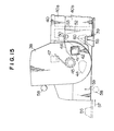
- FIG. 8 is an exploded perspective view of an essential part of the tape cassette in accordance with the second preferred embodiment of the invention, the cassette case 1 (Fig. 1) is constituted by the upper half lc and the lower half lb.
- the recesses 15 are formed in the side plate portions 9, 10 of the lower half lb for supporting the cover-locking piece 36 pivotably in the thicknesswise direction of the tape cassette, while the recess 16 is formed in the side plate portion 9 of the upper half lc for pivotally supporting the front cover 7 through the pivot portion 5.
- the recesses and projections are arranged so as to face each other in positions corresponding to each other in order to pivotally clamp the above-mentioned respective members.
- the front cover 7 is provided with the notch 19 for allowing the entry of the already-described cover-opening member 17 (Figs. 7 and 10) and the notch 21 which allows at some position the entry of the lock-releasing member 18 (Figs.
- the cover-locking piece 36 for releasing the cover-locking piece 36 to enter the space 11 shown in Fig. 1 from the outside of the tape cassette and which faces the insertion direction setting abutment 20 against the cassette holder (not shown) that is once inserted with the tape cassette in order to be properly loaded into the recording and reproducing device (not shown).
- the first projection 23 and the second projection 22 are formed on the inner surface of the side plate portion 8 of the front cover 7, i.e., at positions where the projections 23, 22 project into the space 11 shown in Fig. 1.
- the torsion coil spring 37 is fitted on the pivot portion 5 having both its ends retained by the first and second projections 22, 23 in shapes suitable for retention thereof, respectively.
- the cover-locking piece 36 is first installed on the lower half lb. After the upper and lower halves lc, lb are united together, the side plate portion 8 of the front cover 7 accompanied by the torsion coil spring 37 is outstretched being bent in the widthwise direction of the tape cassete and moved in the direction of the arrow 35 until the pivot portion 5 is inserted into the recess 16 so as to be clamped by the upper and lower halves lc, lb.
- Fig. 9 where the torsion coil spring 37 is retained on the front cover 7 and the pivot portion 5 is inserted in the recess 16 (fig.
- the upper half lc is moved in the direction of the arrow 35 shown in Fig. 10 to assemble the tape cassette.
- one end of the torsion coil sping 37 is allowed to maintain the engagement with the second projection 22 as a part of the front cover 7, the other end is disengaged from the first projection 23 and engaged with the cover-locking piece 36, urging the same in the direction (the direction of the arrow 29) for preventing the front cover 7 from opening.
- the first projection 23 which serves as the retainer for receiving the torsion coil spring (37) functions as the engaging part with the cover-locking piece 36. Moreover, the first projection 23 covers the optical path aperture 33 (Fig. 8) formed in the side plate portion 9 for detecting the leading and trailing end of the tape 1 (Fig. 1) when a transparent leader tape attached thereto crosses light passing between the inside and outside of the tape cassette through the tape 4, thereby preventing dust from entering the inside of the tape cassette through the optical path aperture when the tape cassette is not in use.
- the side plate portion 8 of the front cover 7 is provided with the hole 34 for allowing the passing of light at a position where the front cover 7 is open.
- both the front cover and the cover-locking piece can be urged by the use of only a single urging spring. Moreover, it is possible to improve the assembling efficiency while preventing the disengagement of the urging spring in assembly. Furthermore, it is possible to largely reduce the necessary widthwise dimension of the tape cassette while obtaining satisfactory functions of these front cover and cover-locking piece, thereby making it possible to provide a tape cassette capable of being made more compact.
- a method of covering the optical path aperture will be mainly described hereinunder with reference to Figs. 11 through 15 in combination showing a third preferred embodiment of the invention.
- the basic structure of a tape cassette in accordance with the third embodiment of the invention is also the same as that of the first embodiment so far as is schematically shown in Fig. 1. Therefore, the description thereof is omitted.
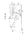
- Fig. 11 is a perspective view of an essential part of the tape cassette in accordance with the third embodiment of the invention
- Fig. 12 is a perspective view of the essential part in the state where its front cover 38, cover-locking piece 39 and the like shown in Fig. 11 are removed and the upper half 40a and the lower half 40b are combined together.
- the upper and lower halves 40a, 40b are provided with an optical path aperture 41 in the same manner as those in the already described first and second embodiments.
- an aperture 42 is formed in a side plate portion 38a of the front cover 38.
- the aperture 42 is, as shown in Fig. 15, located at a position corresponding to the optical path aperture 41 when the front cover 38 is at an open position as shown in Fig.
- a first projection 44 having a height corresponding to the space 11 shown in Fig. 1 and a second projection 47 for retaining one end of a front-cover spring 46 with the other end retained by the cover-locking piece 39 as shown in Figs. 14 and 15 are provided on the surface of the front cover 38 facing case side plate portions 43 in the front parts of the respective upper and lower halves 40a, 40b.
- the front cover 38 is pivotally supported through its pivot portion 45 received by a pivot hole 48 defined by the upper and lower halves 40a, 40b and is constantly urged in the direction of an arrow 49 by the urging force in the direction of the arrow 49 of the front-cover spring 46.
- the cover-locking piece 39 having a thickness corresponding to the space 11 shown in Fig. 1 is supported at its pivot portion 50 so as to be pivotable within a plane thicknesswise of the tape cassette by the pivot hole 51 defined by the upper and lower halves 40a, 40b.
- the cover-locking spring 52 is inserted into a wall portion 53 of the lower half 40b to urge the cover-locking piece 39 in the direction of an arrow 54.
- Fig. 14 shows the state where the front cover 38 is closed and prevented from pivoting, by the cover-locking piece 39.
- the optical path aperture 41 formed in the case side plate portion 43 of the tape cassette, shown also in Fig. 12 is covered by a part of the cover-locking piece 39 and the first projection 44 engaged with the cover-locking piece 39 to prevent the pivoting of the front cover 39, thereby practically preventing foreign matter such as dust from entering the inside of the tape cassette through the optical path aperture.
- the cover-locking piece 39 is released in such a manner that, as shown in Fig.
- a protusion 55 for example, provided on the cassette holder (not shown) into which the tape cassette is once inserted in order to be moved to the final loading position in the recording reproducing device (not shown) relatively advances into the space 11 in the front part of the tape cassette shown in Fig. 1, in the direction of an arrow 57 through a notch 56 (see Fig. 11) of the front cover 38 forming an entering passage in correspondence with the space 11, the abuts against the cover-locking piece 39, causing the latter to pivot overcoming against the urging force in the direction of the arrow 54 of the cover-locking spring 52.
- a stopper 60 is integrally molded with the lower half 40b, having a thickness corresponding to the space 11 shown in Fig. 1.
- the front cover 38 is pivoted in the direction of the arrow 54 by a second means, for example, fingers excluding the cover-opening member 58 as a front-cover opening means, with no more urging force in the direction of the arrow 49 applied by the first means, the stopper 60 abuts against the cover-locking piece 39 to restrain the pivoting in the direction of the arrow 54 of the cover-locking piece 39 forced by the cover-locking spring 52.
- a second means for example, fingers excluding the cover-opening member 58 as a front-cover opening means
- the optical path aperture 41 is covered by both the cover-locking piece 39 and the first projection 44.
- the optical path aperture 41 is covered by only a cover-locking piece 39' which engages a first projection 44' of the front cover 38 in order to hold the pivoting of the front cover 38 when it is not in use, by changing the position of the pivot portion 50 of the cover-locking piece 39 as its pivot point as well as by modifying the shape and by replacing the position of the projection 44.
- the front cover 38 is released from the restraint of pivoting laid by the cover-locking piece 39', the front cover 38 is pivoted by the cover-opening member 58 into the position shown in Fig. 17.
- the apertue 42 formed in the side plate portion 38a of the front cover 38 comes to the position corresponding to the optical path aperture 41, thereby allowing an optical path to be formed.
- any gap at the junction between the cover-lockig piece 39 and the projection 44 may allow the intrusion of foreign matter therethough. According to this embodiment, however, the intrusion of foreign matter is completely prevented by covering the optical path aperture 41 with only the cover-locking piece 39'.
- the tape cassette in accordance with the invention has the front cover which pivots to cover the tape stretched along the front surface of the cassette case and is provided with the side plate portion facing the corresponding one of the case side plate portions of the cassette case with a predetermined space interposed therebetween, together with the cover-locking piece which pivots in the thicknesswise direction of the cassette case within the space defined by the case side plate portion and the side plate portion of the front cover and engages the front cover.
Landscapes
- Packaging Of Annular Or Rod-Shaped Articles, Wearing Apparel, Cassettes, Or The Like (AREA)
Applications Claiming Priority (10)
| Application Number | Priority Date | Filing Date | Title |
|---|---|---|---|
| JP46668/82 | 1982-03-23 | ||
| JP4111182U JPS58144677U (ja) | 1982-03-23 | 1982-03-23 | テ−プカセツト |
| JP41111/82U | 1982-03-23 | ||
| JP4666882A JPS58164066A (ja) | 1982-03-23 | 1982-03-23 | テ−プカセツト |
| JP4756282A JPS58164068A (ja) | 1982-03-24 | 1982-03-24 | テ−プカセツト |
| JP47562/82 | 1982-03-24 | ||
| JP4849882U JPS58151982U (ja) | 1982-04-02 | 1982-04-02 | テ−プカセツト |
| JP48498/82U | 1982-04-02 | ||
| JP99909/82U | 1982-06-30 | ||
| JP9990982U JPS595079U (ja) | 1982-06-30 | 1982-06-30 | テ−プカセツト |
Publications (2)
| Publication Number | Publication Date |
|---|---|
| EP0090573A1 true EP0090573A1 (de) | 1983-10-05 |
| EP0090573B1 EP0090573B1 (de) | 1986-08-06 |
Family
ID=27522137
Family Applications (1)
| Application Number | Title | Priority Date | Filing Date |
|---|---|---|---|
| EP83301574A Expired EP0090573B1 (de) | 1982-03-23 | 1983-03-21 | Bandkassette |
Country Status (4)
| Country | Link |
|---|---|
| US (1) | US4591936A (de) |
| EP (1) | EP0090573B1 (de) |
| KR (1) | KR870000048B1 (de) |
| DE (1) | DE3365072D1 (de) |
Cited By (18)
| Publication number | Priority date | Publication date | Assignee | Title |
|---|---|---|---|---|
| EP0109682A2 (de) * | 1982-11-20 | 1984-05-30 | Hitachi Maxell Ltd. | Aufnahmebandkassette |
| FR2537762A1 (fr) * | 1982-12-10 | 1984-06-15 | Victor Company Of Japan | Cassette a bande comportant une fenetre transparente |
| FR2545253A1 (fr) * | 1983-04-29 | 1984-11-02 | Sony Corp | Cassette de bande |
| EP0125688A2 (de) * | 1983-05-17 | 1984-11-21 | Hitachi Maxell Ltd. | Bandkassette |
| EP0136507A1 (de) * | 1983-08-30 | 1985-04-10 | Agfa-Gevaert AG | Magnetbandkassette |
| FR2562703A1 (fr) * | 1984-04-10 | 1985-10-11 | Sony Corp | Cassette de bande magnetique |
| EP0169544A2 (de) * | 1984-07-23 | 1986-01-29 | Sony Corporation | Bandkassette |
| EP0179169A1 (de) * | 1984-09-14 | 1986-04-30 | Sony Corporation | Videobandkassette |
| EP0189989A2 (de) * | 1985-01-19 | 1986-08-06 | Sony Corporation | Magnetbandkassette mit Federelement |
| EP0316178A2 (de) * | 1987-11-11 | 1989-05-17 | Sony Corporation | Bandkassette |
| EP0323100A2 (de) * | 1987-12-29 | 1989-07-05 | Sony Corporation | Bandkassette |
| EP0488599A2 (de) * | 1990-11-30 | 1992-06-03 | Matsushita Electric Industrial Co., Ltd. | Bandkassette |
| EP0534377A2 (de) * | 1991-09-24 | 1993-03-31 | Hitachi Maxell Ltd. | Magnetbandkassette |
| EP0707314A3 (de) * | 1994-10-11 | 1996-05-01 | Sony Corp | |
| EP0829877A2 (de) * | 1994-07-27 | 1998-03-18 | Sony Corporation | Kassettenstruktur mit Deckel |
| EP0862176A2 (de) * | 1997-02-05 | 1998-09-02 | Fuji Photo Film Co., Ltd. | Magnetbandkassette |
| WO1999045541A1 (en) * | 1998-03-04 | 1999-09-10 | Fuji Photo Film Co., Ltd. | Magnetic tape cassette |
| WO1999059151A1 (en) * | 1998-05-13 | 1999-11-18 | Fuji Photo Film Co., Ltd. | Magnetic tape cassette |
Families Citing this family (10)
| Publication number | Priority date | Publication date | Assignee | Title |
|---|---|---|---|---|
| JPS593759A (ja) * | 1982-06-30 | 1984-01-10 | Hitachi Ltd | 磁気テ−プカ−トリツジの蓋ロツク機構 |
| DE3441156A1 (de) * | 1984-11-10 | 1986-05-15 | Agfa-Gevaert Ag, 5090 Leverkusen | Frontklappenverriegelung von magnetbandkassetten, insbesondere videobandkassetten |
| EP0287664B1 (de) * | 1986-08-25 | 1994-05-11 | Konica Corporation | Magnetbandkassette |
| US5169088A (en) * | 1989-08-04 | 1992-12-08 | Shape, Inc. | Video cassette combined dust door and dust door latch spring |
| US5092536A (en) * | 1990-05-11 | 1992-03-03 | Paul J. Gelardi | Integrally molded recyclable video tape cassette |
| US5114092A (en) * | 1991-01-10 | 1992-05-19 | Paul J. Gelardi | Low cost video cassette |
| DE69130109T2 (de) * | 1990-05-11 | 1999-05-12 | L C V Associates | Vollstaendig aus einer form gegossene wiederverwertbare bildbandkassette |
| US5201476A (en) * | 1990-05-11 | 1993-04-13 | Paul J. Gelardi | Welded video cassette |
| US5240201A (en) * | 1990-05-11 | 1993-08-31 | Paul J. Gelardi | Integrally molded recyclable video tape cassette |
| US5308015A (en) * | 1992-05-21 | 1994-05-03 | Lcv Associates | Dust door arrangement for video cassettes |
Citations (4)
| Publication number | Priority date | Publication date | Assignee | Title |
|---|---|---|---|---|
| DE2837887A1 (de) * | 1977-12-12 | 1979-06-13 | Tdk Electronics Co Ltd | Bandkassette |
| DE2656199B2 (de) * | 1975-12-13 | 1980-01-31 | Victor Company Of Japan, Ltd., Yokohama, Kanagawa (Japan) | |
| GB2068334A (en) * | 1980-01-28 | 1981-08-12 | Tdk Electronics Co Ltd | Mounting pivotable cover on magnetic tape cassette casing |
| EP0045084A2 (de) * | 1980-07-28 | 1982-02-03 | Hitachi Maxell Ltd. | Magnetbandkassette |
Family Cites Families (11)
| Publication number | Priority date | Publication date | Assignee | Title |
|---|---|---|---|---|
| US3900170A (en) * | 1972-06-29 | 1975-08-19 | Sony Corp | Tape cassette |
| US4173319A (en) * | 1975-12-13 | 1979-11-06 | Victor Company Of Japan, Limited | Magnetic tape cassette |
| US4323207A (en) * | 1977-05-11 | 1982-04-06 | Minnesota Mining And Manufacturing Company | Latch assembly for a video tape cassette |
| JPS57123573A (en) * | 1981-01-20 | 1982-08-02 | Victor Co Of Japan Ltd | Adapter for tape cassette |
| AU539874B2 (en) * | 1981-11-04 | 1984-10-18 | Matsushita Electric Industrial Co., Ltd. | Cover locking tape cassette |
| JPS58128069A (ja) * | 1982-01-25 | 1983-07-30 | Sony Corp | テ−プカセツト |
| US4485990A (en) * | 1982-03-10 | 1984-12-04 | Hitachi Maxell, Ltd. | Recording tape cassette |
| JPS58164066A (ja) * | 1982-03-23 | 1983-09-28 | Matsushita Electric Ind Co Ltd | テ−プカセツト |
| JPS58164068A (ja) * | 1982-03-24 | 1983-09-28 | Matsushita Electric Ind Co Ltd | テ−プカセツト |
| JPS58164067A (ja) * | 1982-03-23 | 1983-09-28 | Matsushita Electric Ind Co Ltd | テ−プカセツト |
| CA1202287A (en) * | 1982-05-12 | 1986-03-25 | Shinichi Goto | Recording tape cartridge |
-
1983
- 1983-03-21 DE DE8383301574T patent/DE3365072D1/de not_active Expired
- 1983-03-21 EP EP83301574A patent/EP0090573B1/de not_active Expired
- 1983-03-22 KR KR1019830001144A patent/KR870000048B1/ko not_active IP Right Cessation
- 1983-03-23 US US06/478,208 patent/US4591936A/en not_active Expired - Lifetime
Patent Citations (4)
| Publication number | Priority date | Publication date | Assignee | Title |
|---|---|---|---|---|
| DE2656199B2 (de) * | 1975-12-13 | 1980-01-31 | Victor Company Of Japan, Ltd., Yokohama, Kanagawa (Japan) | |
| DE2837887A1 (de) * | 1977-12-12 | 1979-06-13 | Tdk Electronics Co Ltd | Bandkassette |
| GB2068334A (en) * | 1980-01-28 | 1981-08-12 | Tdk Electronics Co Ltd | Mounting pivotable cover on magnetic tape cassette casing |
| EP0045084A2 (de) * | 1980-07-28 | 1982-02-03 | Hitachi Maxell Ltd. | Magnetbandkassette |
Cited By (39)
| Publication number | Priority date | Publication date | Assignee | Title |
|---|---|---|---|---|
| EP0109682A3 (en) * | 1982-11-20 | 1985-10-16 | Hitachi Maxell Ltd. | Recording tape cassette |
| EP0109682A2 (de) * | 1982-11-20 | 1984-05-30 | Hitachi Maxell Ltd. | Aufnahmebandkassette |
| FR2537762A1 (fr) * | 1982-12-10 | 1984-06-15 | Victor Company Of Japan | Cassette a bande comportant une fenetre transparente |
| FR2545253A1 (fr) * | 1983-04-29 | 1984-11-02 | Sony Corp | Cassette de bande |
| EP0125688A2 (de) * | 1983-05-17 | 1984-11-21 | Hitachi Maxell Ltd. | Bandkassette |
| EP0125688A3 (en) * | 1983-05-17 | 1986-02-12 | Hitachi Maxell Ltd. | Recording tape cartridge |
| EP0136507A1 (de) * | 1983-08-30 | 1985-04-10 | Agfa-Gevaert AG | Magnetbandkassette |
| US4564120A (en) * | 1983-08-30 | 1986-01-14 | Agfa-Gevaert Aktiengesellschaft | Magnetic tape cassette |
| FR2562703A1 (fr) * | 1984-04-10 | 1985-10-11 | Sony Corp | Cassette de bande magnetique |
| EP0169544A2 (de) * | 1984-07-23 | 1986-01-29 | Sony Corporation | Bandkassette |
| EP0169544A3 (en) * | 1984-07-23 | 1987-08-26 | Sony Corporation | Tape cassette |
| EP0179169A1 (de) * | 1984-09-14 | 1986-04-30 | Sony Corporation | Videobandkassette |
| US4633355A (en) * | 1984-09-14 | 1986-12-30 | Sony Corporation | Video tape cassette with easy assembly of its lid and reel brakes |
| EP0189989A2 (de) * | 1985-01-19 | 1986-08-06 | Sony Corporation | Magnetbandkassette mit Federelement |
| EP0189989A3 (en) * | 1985-01-19 | 1987-11-19 | Sony Corporation | Magnetic tape cassette with improved spring member |
| EP0316178A3 (en) * | 1987-11-11 | 1990-03-07 | Sony Corporation | Tape cassette |
| EP0316178A2 (de) * | 1987-11-11 | 1989-05-17 | Sony Corporation | Bandkassette |
| US4984122A (en) * | 1987-11-11 | 1991-01-08 | Sony Corporation | Tape cassette with air blocking baffles |
| EP0323100A2 (de) * | 1987-12-29 | 1989-07-05 | Sony Corporation | Bandkassette |
| EP0323100A3 (en) * | 1987-12-29 | 1990-02-21 | Sony Corporation | Tape cassette |
| US5075810A (en) * | 1987-12-29 | 1991-12-24 | Sony Corporation | Tape cassette with sealed light aperture |
| EP0488599B1 (de) * | 1990-11-30 | 1997-07-16 | Matsushita Electric Industrial Co., Ltd. | Bandkassette |
| US5796563A (en) * | 1990-11-30 | 1998-08-18 | Matsushita Electric Industrial Co., Ltd. | Tape cassette having locking front cover with ribs or projection |
| US5654855A (en) * | 1990-11-30 | 1997-08-05 | Matsushita Electric Industrial Co., Ltd. | Tape cassette having ribs for regulating axial movement of the tape reels |
| US5475555A (en) * | 1990-11-30 | 1995-12-12 | Matsushita Electric Industrial Co., Ltd. | Cassette condition indicating device having plug with multiple selectable positions |
| EP0488599A2 (de) * | 1990-11-30 | 1992-06-03 | Matsushita Electric Industrial Co., Ltd. | Bandkassette |
| EP0534377A3 (en) * | 1991-09-24 | 1993-11-18 | Hitachi Maxell | Lid locking mechanism for magnetic tape cassette |
| EP0534377A2 (de) * | 1991-09-24 | 1993-03-31 | Hitachi Maxell Ltd. | Magnetbandkassette |
| EP0829877A2 (de) * | 1994-07-27 | 1998-03-18 | Sony Corporation | Kassettenstruktur mit Deckel |
| EP0829877A3 (de) * | 1994-07-27 | 1998-04-15 | Sony Corporation | Kassettenstruktur mit Deckel |
| EP0707314A3 (de) * | 1994-10-11 | 1996-05-01 | Sony Corp | |
| CN1084021C (zh) * | 1994-10-11 | 2002-05-01 | 索尼公司 | 带盖的磁带盒的防尘肋板结构 |
| EP0862176A3 (de) * | 1997-02-05 | 1999-04-21 | Fuji Photo Film Co., Ltd. | Magnetbandkassette |
| US6024315A (en) * | 1997-02-05 | 2000-02-15 | Fuji Photo Film Co., Ltd. | Magnetic tape cassette |
| US6102318A (en) * | 1997-02-05 | 2000-08-15 | Fuji Photo Film Co., Ltd. | Magnetic tape cassette |
| US6286776B1 (en) | 1997-02-05 | 2001-09-11 | Fuji Photo Film Co., Ltd. | Magnetic tape cassette |
| EP0862176A2 (de) * | 1997-02-05 | 1998-09-02 | Fuji Photo Film Co., Ltd. | Magnetbandkassette |
| WO1999045541A1 (en) * | 1998-03-04 | 1999-09-10 | Fuji Photo Film Co., Ltd. | Magnetic tape cassette |
| WO1999059151A1 (en) * | 1998-05-13 | 1999-11-18 | Fuji Photo Film Co., Ltd. | Magnetic tape cassette |
Also Published As
| Publication number | Publication date |
|---|---|
| DE3365072D1 (en) | 1986-09-11 |
| EP0090573B1 (de) | 1986-08-06 |
| US4591936A (en) | 1986-05-27 |
| KR870000048B1 (ko) | 1987-02-07 |
| KR840004291A (ko) | 1984-10-10 |
Similar Documents
| Publication | Publication Date | Title |
|---|---|---|
| EP0090573A1 (de) | Bandkassette | |
| US4807077A (en) | Short time recording tape cassette having a larger open space than that of a long time recording tape cassette | |
| US4449677A (en) | Tape cassette | |
| EP0064859B1 (de) | Bandkassette | |
| US4484248A (en) | Magnetic recording tape cartridge | |
| EP0406943A1 (de) | System zur Aufzeichnung/Wiedergabe von Signalen auf/vom Magnetband und Gerät und Kassette zur Verwendung in diesem System | |
| NZ203068A (en) | Tape cassette:covers enclose front tape run | |
| US4323207A (en) | Latch assembly for a video tape cassette | |
| EP0052479A2 (de) | Bandkassette | |
| EP0449330B1 (de) | Bandkassettenladesystem | |
| KR100306182B1 (ko) | 테이프카세트 | |
| US4607308A (en) | Magnetic tape cassette with dual guard panel structure | |
| EP0045085B1 (de) | Magnetbandkassette | |
| US4672497A (en) | Magnetic tape cassette | |
| US4422599A (en) | Magnetic tape cassette | |
| US5146376A (en) | Tape cassette | |
| JPS6334552B2 (de) | ||
| KR19980018861A (ko) | 테이프 카셋트 (tape cassette) | |
| US5786966A (en) | Magnetic tape cassette having improved guard panel structure | |
| US5335129A (en) | Interchangeable compact tape cassette | |
| JP2629431B2 (ja) | テープカセット | |
| JPH0222874Y2 (de) | ||
| JP2570539B2 (ja) | テープカセット | |
| KR0136707B1 (ko) | 테이프 카세트(Tape cassette) | |
| KR850000855Y1 (ko) | 원판형 기록매체 수납케이스 |
Legal Events
| Date | Code | Title | Description |
|---|---|---|---|
| PUAI | Public reference made under article 153(3) epc to a published international application that has entered the european phase |
Free format text: ORIGINAL CODE: 0009012 |
|
| AK | Designated contracting states |
Designated state(s): DE FR GB NL |
|
| 17P | Request for examination filed |
Effective date: 19840315 |
|
| GRAA | (expected) grant |
Free format text: ORIGINAL CODE: 0009210 |
|
| AK | Designated contracting states |
Kind code of ref document: B1 Designated state(s): DE FR GB NL |
|
| REF | Corresponds to: |
Ref document number: 3365072 Country of ref document: DE Date of ref document: 19860911 |
|
| ET | Fr: translation filed | ||
| PLBE | No opposition filed within time limit |
Free format text: ORIGINAL CODE: 0009261 |
|
| STAA | Information on the status of an ep patent application or granted ep patent |
Free format text: STATUS: NO OPPOSITION FILED WITHIN TIME LIMIT |
|
| 26N | No opposition filed | ||
| REG | Reference to a national code |
Ref country code: GB Ref legal event code: 746 Effective date: 19950224 |
|
| REG | Reference to a national code |
Ref country code: FR Ref legal event code: D6 |
|
| REG | Reference to a national code |
Ref country code: GB Ref legal event code: IF02 |
|
| PGFP | Annual fee paid to national office [announced via postgrant information from national office to epo] |
Ref country code: FR Payment date: 20020312 Year of fee payment: 20 |
|
| PGFP | Annual fee paid to national office [announced via postgrant information from national office to epo] |
Ref country code: GB Payment date: 20020320 Year of fee payment: 20 |
|
| PGFP | Annual fee paid to national office [announced via postgrant information from national office to epo] |
Ref country code: NL Payment date: 20020328 Year of fee payment: 20 |
|
| PGFP | Annual fee paid to national office [announced via postgrant information from national office to epo] |
Ref country code: DE Payment date: 20020404 Year of fee payment: 20 |
|
| PG25 | Lapsed in a contracting state [announced via postgrant information from national office to epo] |
Ref country code: GB Free format text: LAPSE BECAUSE OF EXPIRATION OF PROTECTION Effective date: 20030320 |
|
| PG25 | Lapsed in a contracting state [announced via postgrant information from national office to epo] |
Ref country code: NL Free format text: LAPSE BECAUSE OF EXPIRATION OF PROTECTION Effective date: 20030321 |
|
| REG | Reference to a national code |
Ref country code: GB Ref legal event code: PE20 |