EP0090348A2 - Bundling apparatus - Google Patents
Bundling apparatus Download PDFInfo
- Publication number
- EP0090348A2 EP0090348A2 EP83102905A EP83102905A EP0090348A2 EP 0090348 A2 EP0090348 A2 EP 0090348A2 EP 83102905 A EP83102905 A EP 83102905A EP 83102905 A EP83102905 A EP 83102905A EP 0090348 A2 EP0090348 A2 EP 0090348A2
- Authority
- EP
- European Patent Office
- Prior art keywords
- carrier
- bundled
- objects
- catcher
- band
- Prior art date
- Legal status (The legal status is an assumption and is not a legal conclusion. Google has not performed a legal analysis and makes no representation as to the accuracy of the status listed.)
- Granted
Links
Images


Classifications
-
- B—PERFORMING OPERATIONS; TRANSPORTING
- B65—CONVEYING; PACKING; STORING; HANDLING THIN OR FILAMENTARY MATERIAL
- B65B—MACHINES, APPARATUS OR DEVICES FOR, OR METHODS OF, PACKAGING ARTICLES OR MATERIALS; UNPACKING
- B65B27/00—Bundling particular articles presenting special problems using string, wire, or narrow tape or band; Baling fibrous material, e.g. peat, not otherwise provided for
- B65B27/08—Bundling paper sheets, envelopes, bags, newspapers, or other thin flat articles
Definitions
- the present invention relates to a bundling apparatus for collectively bundling objects to be bundled stacked in a pile, and more specifically, to a bundling apparatus in which a band material is wound around objects to be bundled and both ends of the band material are bonded together to securely bundle the objects.
- Prior art bundling apparatuses of this type have a band material passed along a guide member to form a loop, through which objects to be bundled, such as a stack of sheets, are inserted. After the guide member is drawn out of the looped band material, the band material is tightened and both its end portions are joined and thermally welded together to bundle the stack of sheets.
- the width or diameter of the guide member must be greater than the width of the stack of sheets to be bundled. As a result, the size of the apparatus is increased. If the guide member is circular in shape, the width of the sheets inserted therein must be less than the diameter of the guide member. Thus, the apparatus cannot be well adapted to sheets of different widths. If the guide member is formed of guide bars facing each other, it requires a guide bar transfer mechanism for improved adaptability to the sheet width, thus complicating the construction of the apparatus.
- the present invention has been developed in consideration of these circumstances, and is intended to provide a bundling apparatus which is improved in adaptability to the size of objects to be bundled and which is also compact in design.
- a bundling apparatus which comprises: transfer means for receiving stacked objects to be bundled and transferring the same along a prescribed path of travel; and bundling means for bundling the objects to be bundled transferred thereto by the transfer means, said bundling means including winding means for winding a band around the objects to be bundled so that one end of the band is joined with another portion of the band, and bonding means for bonding together the joined end portions of the band wound around the objects to be bundled, said transfer means including a carrier bearing thereon the objects to be bundled and capable of moving between a first position where the carrier receives thereon the objects to be bundled and a second position inside the winding means, and first driving means for moving the carrier from the first position to the second position after the objects to be bundled are set on the carrier, and then moving the carrier from the second position to the first position, said winding means including a catcher retaining the one end of the band and capable of moving across the path of travel, the catcher being moved along
- the present invention provides a bundling apparatus characterized in that both the carrier to transfer the objects to be bundled and the catcher retaining the bundling band and revolving in the object transfer direction are driven relatively so that the band is wound around the objects while they are being transferred.
- the bundling apparatus serves to bundle objects to be bundled, e.g., a stack of bank notes, and mainly comprises a transfer mechanism 1 and a bundling mechanism 2.
- numeral 3 designates a backup plate which carries thereon and vertically transfers a specified number of bank notes stacked by a stacking apparatus (not shown).
- the transfer mechanism 1 receives the bank notes which are lowered on the backup plate 3 as the backup plate 3 descends and then delivers them to the bundling mechanism 2.
- the bundling apparatus comprises a pair of side frames 4A and 4B standing on a base (not shown).
- the transfer mechanism 1 is attached to these side frames 4A and 4B.
- a guide rod 6 extends parallel to the one side frame 4A, and is supported at both ends by brackets 5 (Fig. 2) attached to the lateral side of the one side frame 4A.
- a guide rail 7 is attached to the other side frame 4B, facing the guide rod 6.
- a carrier 8 is provided between the guide rail 7 and the guide rod 6 so as to be movable along them.
- the carrier 8 includes a frame 9 which is substantially U-shaped in a two-dimensional configuration.
- a plurality of guide rollers 10 in rolling contact with the guide rail 7 are rotatably attached to one lateral portion of the frame 9.
- Attached to the other lateral portion of the frame 9 is a side bracket 12 with pinch rollers 11 to hold the guide rod 6 from both upper and lower sides.
- the side bracket 12 is fitted with a first bed 13A having a cut portion and extending horizontally.
- Second and third beds 13B and 13C are attached to the basal part of the frame 9 by means of an intermediate bracket 14.
- the second and third beds 13B and 13C are flush with and spaced apart from the first bed 13A.
- the space between the first and second beds 13A and 13B which is greater than the width of a band to be mentioned later, forms a gap portion 13D located in the position where the band is wound by a catcher 72 (to be mentioned later).
- the beds 13A to 13C of the carrier 8 and the backup plate 3 are nested into each other. Accordingly, the backup plate 3 can descend from an upper position A O to a lower position A 2 below the beds 13A to 13C via an intermediate position A 1 substantially flush with the beds 13A to 13C, as shown in Figs. lA and 1B.
- a carrier driver 15 is provided to move the carrier 8 along the guide rod 6.
- the carrier driver 15 has a stay 19 which is fixed to the side frames 4A and 4B at both ends.
- the stay 19 is fitted with a reversible motor 18 having a drive sprocket 17A.
- the drive sprocket 17A faces one end of the one side frame 4A.
- An idle sprocket 17B is rotatably attached to the other end of the one side frame 4A.
- An endless chain 20 is stretched between the two sprockets 17A and 17B.
- a detecting piece 21 and an engaging roller 22 are attached by means of a link holder 23 to one of links (not shown) constituting the chain 20.
- the side bracket 12 of the carrier 8 is fitted with a transmission member 24 having a cut portion 24A in which the engaging roller 22 is fitted.
- the carrier 8 constructed in this manner can move in the longitudinal direction following the movement of the chain 20 through the medium of the engaging roller 22 and the transmission member 24.
- the carrier 8 receives the bank notes from the backup plate 3 in a carrier home position CRHP, indicated by a solid line in Figs. lA, 1B and 2.
- the carrier 8 is transferred by the carrier driver 15 to a carrier stop position CRSP indicated by a one dot and dashed line in Figs. lA, 1B and 2, where the bank notes are bundled by the bundling mechanism 2.
- the motor 18 is reversed, the carrier 8 is moved back to a carrier back position CRBP indicated by two-dots and dashed line in Figs. lA, 1B and 2.
- the motor 18 is rotated in the forward direction, so that the carrier 8 is returned to the carrier home position CRHP.
- one cycle of movement for the carrier 8 is completed.
- a scraper as a bundle removal mechanism 26 is fixedly attached to the base (not shown).
- the scraper 26 is nested with the beds 13A to 13C of the carrier 8, and abuts against a bundle of the bank notes (hereinafter referred to simply as a bundle) on the carrier 8. Accordingly, while the carrier 8 is moving from the carrier stop position CRSP to the carrier back position CRBP, the bundle on the carrier 8 engages the scraper 26 to be prevented from moving, and then drops from the carrier 8. Thus, the bundle can be delivered to some subsequent process (not described) by way of a chute 27 under the scraper 26.
- the use of the scraper 26 enables the bundle to be removed securely from the carrier 8 by a very simple structure.
- the carrier 8 is further provided with an auxiliary clamp mechanism 29 for preventing the stack of bank notes on the beds 13A to 13C from collapsing during transfer.
- the auxiliary clamp mechanism 29 also serves to orient the bank notes delivered from the backup plate 3 onto the carrier 8 in the longitudinal direction (i.e., the bank notes are laid on the carrier 8 so that their longitudinal direction is at right angles to the moving direction of the carrier 8).
- one end portion of a clamp bracket 30 is attached to the frame 9 of the carrier 8.
- a rod 31 is vertically passed through the other end portion of the clamp bracket 30.
- a clamp holder 32 with a substantially U-shaped cross section is pivotally mounted on the rod 31 so as to be rockable around the rod 31.
- a clamp plate 33 lies over the clamp holder 32 and is swingable around a hinge 32A within a vertical plane.
- a first cam follower 35 rotatable on a horizontal axis is attached to the proximal end portion of the clamp plate 33 by means of a stud 34.
- a curved aligning rod 36 is attached to the distal end portion of the clamp plate 33.
- a second cam follower 37 rotatable on a vertical axis is attached to the lower end portion of the clamp holder 32.
- Fixed on the other side frame 4B is a fixed cam block 38 which engages the first and second cam followers 35 and 37.
- the fixed cam block 38 is formed of an L-shaped channel bar, comprising a first cam face 38A at the upper surface portion (Fig. 3) to allow for the vertical swinging of the clamp plate 33 and a second cam face 38B at the lateral face portion (Fig. 3) for the horizontal rocking of the clamp holder 32.
- the right end portion (Fig. 2) of the first cam face 38A is rounded and bent downward and the remaining portion thereof is straight.
- first cam follower 35 reaches the right end portion of the first cam face 38A, it comes down to cause the clamp plate 33 to swing counterclockwise (Fig. 3) around the hinge 32A.
- the right end portion (Fig. 2) of the second cam face 28B is rounded and bent inward and the remaining portion thereof is straight. Therefore, when the second cam follower 37 reaches the right end portion of the second cam face 38B, it moves inward to cause the clamp holder 32 to rock clockwise (Fig. 2) around the rod 31.
- the right end portion of the first cam face 38A is located on the right (Fig. 2) of the right end portion of the second cam face 38B.
- the clamp holder 32 is urged to rock clockwise (Fig. 2) by an urging member (not shown).
- the second cam follower 37 is pushed by the straight portion of the second cam face 38B, so that the clamp plate 33 is located in the position indicated by the solid line in Fig. 2.
- the clamp plate 33 is removed from the region over the first to third beds, 13A to 13C.
- the first cam follower 35 lies on the straight portion of the first cam face 38A, so that the clamp plate 33 is kept substantially horizontal, as indicated by the solid line in Fig. 3.
- the clamp plate 33 is held above the stack of bank notes laid on the first to third beds 13A to 13C.
- the second cam follower 37 is disengaged from the second cam face 38B and then the first cam follower 35 is disengaged from the first cam face 38A, at the right end portions thereof, so that the clamp plate 33 gradually swings clockwise (Fig. 3) around the rod 31, urged by the urging member (not shown), thereafter, the clamp plate 33 gradually swings counterclockwise (Fig. 3) around the hinge 32A.
- the aligning rod 36 at the distal end of the clamp plate 33 engages the longitudinal edges of the bank notes on the beds 13A to 13C, and pushes the bank notes to back portions 13a to 13c of the beds 13A to 13C to align or true up the bank notes.
- the distal end portion of the clamp plate 33 presses on the top of the stack of bank notes trued up by the aligning rod 36, thereby preventing the stack of bank notes from collapsing during the transfer.
- the auxiliary clamp mechanism 29 has an aligning function. Accordingly, no trouble will be caused if the carrier 8 in the carrier home position CRHP is subject to errors in location so that the position of the stack of bank notes on the carrier 8 is deviated. Even though the bank notes on the beds 13A to 13C vary in width, moreover, it is unnecessary to change the carrier home position CRHP and the position of the stacking device including the backup plate 3. Thus, the apparatus of the present invention can enjoy improved applicability to bank notes of varied widths. Since the bank notes are aligned during the transfer of the carrier 8, the processing speed of the apparatus may be increased.
- the bundling mechanism 2 comprises a feeder 40 for supplying a band material coated on one side with a thermally fusible material, e.g., a thermal adhesive tape MT with a coating layer CF on the lower surface as in Fig. 1B, a winder 41 for winding the thermal adhesive tape MT from the feeder 40 around the stack of bank notes delivered thereto by the carrier 8, a main clamp mechanism 42 for compressing and holding the stack of bank notes wound with the thermal adhesive tape MT by the winder 41, and a heat bonding mechanism 43 for thermally bonding the thermal adhesive tape MT around the stack of bank notes.
- the winder 41 includes a turning mechanism 41A for turning up one end portion of the wound tape MT.
- a stay 45 is stretched between the two side frames 4A and 4B in the vicinity of the carrier stop position CRSP.
- the feeder 40 is attached to the substantially central portion of the stay 45 so that it may be located in the gap portion 13D between the first and second beds 13A and 13B when the carrier 8 is positioned as shown in Fig. 2.
- a feeder bracket 46 is attached to the stay 45.
- One end portion of a pinch roller holder 47 is pivotally mounted on the feeder bracket 46 so that the pinch roller holder 47 can rock around a shaft 47A.
- a pinch roller 48 is rotatably supported on the other end portion of the pinch roller holder 47.
- a feed roller 49 is mounted on a drive shaft 50 so as to be in contact with the pinch roller 48.
- An urging member e.g., a leaf spring 51
- the distal end portion of the leaf spring 51 engages the tip portion of an adjust screw 52 attached to the feeder bracket 46.
- the contact pressure of the pinch roller 48 on the feed roller 49 may be finely adjusted by turning the adjust screw 52.
- the thermal adhesive tape MT is held between the pinch roller 48 and the feed roller 49, and is fed as the feed roller 49 rotates in the clockwise direction of Fig. 1B and returned as the feed roller 49 rotates in the counterclockwise direction.
- a fixed cutting edge 53A and a movable cutting edge 53B which reciprocates along the fixed cutting edge 53A in accordance with the operation of a rotary solenoid 54.
- a guide plate 55 and a guide roller 56 for guiding the thermal adhesive tape MT are arranged on the down stream side of the cutting edges 53A and 53B.
- a drive mechanism 49A for the feed roller 49 comprises an electromagnetic clutch/brake 57 attached to the middle portion of the drive shaft 50, an idle gear 58 mounted on the other end portion of the drive shaft 50, a drive gear 59 in mesh with the idle gear 58, and a feed motor 60 for rotating the drive gear 59.
- the feed motor 60 is a reversible motor, and it is reversed after the thermal adhesive tape MT is moved around the bank notes by the winder 41.
- the wound thermal adhesive tape MT is supported in the middle by the guide roller 56, and so is pulled back as the feed roller 49 rotates in the counterclockwise direction of Fig. 2.
- the bank notes are bound tight.
- a bearing block 65 containing therein a radial bearing (not shown) and other members is attached to the one side frame 4A in the vicinity of the carrier stop position CRSP.
- a drive shaft 66 is rotatably fitted in the bearing block 65 to be supported thereby.
- a stop collar 67 and a stop plate 68 are attached, respectively, to the proximal part and the distal end part of that portion of the drive shaft 66 which projects inside the one side frame 4A.
- the stop collar 67 and the stop plate 68 can rotate together with the drive shaft 66.
- a guide shaft 69 extends parallel to the drive shaft 66.
- the drive shaft 66 and the guide shaft 69 constitute a narrow guide 70.
- a sliding block 71 is fitted in the narrow guide 70 so as to be slidable along the shafts 66 and 69 between the stop collar 67 and the stop plate 68.
- the stroke of the sliding block 71 is longer than the width of the thermal adhesive tape MT.
- the sliding block 71 is provided with the catcher 72 to hold the thermal adhesive tape MT supplied from the feeder 40.
- Figs. 4A and 5 show the catcher 72 in detail.
- the catcher 72 includes a platelike fixed catcher member 72A screwed to the sliding block 71, and a platelike swinging catcher member 72B swingably attached to the sliding block 71 and capable of being joined with the fixed catcher member 72A.
- An L-shaped rocking hook portion 72C is formed at the proximal end portion of the swinging catcher member 72B. By pulling the rocking hook portion 72C to the left of Fig. 4A, the swinging catcher member 72B is separated from the fixed catcher member 72A at a given angle. As shown in Fig.
- a hook lever 73 is attached to that portion of the sliding block 71 which forms an angle of approximately 90° around the drive shaft 66 with the rocking hook portion 72C.
- the hook lever 73 is pulled to the left of Fig. 4A, the sliding block 71 is moved to the left, so that the catcher 72 is taken out of the range of travel of the thermal adhesive tape MT. Namely, the catcher 72 is disengaged from the thermal adhesive tape MT.
- the hook lever 73, along with the catcher 72 and the hook portion 72C, can revolve around the drive shaft 66 as the shaft 66 rotates, while keeping the relative positions shown in Fig. 5.
- a fixed angle 6 is kept between a plane including the drive shaft 66 and the catcher 72, and an extending surface of the catcher 72.
- This special arrangement constitutes the turning mechanism 41A.
- tape holding portions 72D are formed with a plurality of ridges extending along the extending direction of the catcher 72, that is, at right angles to the tape winding direction.
- a catcher driver 75 is attached to the one side frame 4A.
- the catcher driver 75 serves to rotate the catcher 72 as the drive shaft 66 rotates.
- the catcher driver 75 comprises a first gear 75A to rotate together and coaxially with the idle sprocket 17B, a second gear 75B in mesh with the first gear 75A, a third gear 75C to rotate together and coaxially with the second gear 75B, and a fourth gear 75E coaxially fixed to one end of the drive shaft 66.
- a rotatary force is transmitted from the third gear 75C to the fourth gear 75E by means of a timing belt 75D which is stretched between the third gear 75C and fourth gear 75E.
- the catcher driver 75 is driven by the same drive source (motor) 18 with the carrier dirver 15. Accordingly, the catcher 72 rotates interlocking with the moving carrier 8.
- the catcher 72 holding the forward end portion of the thermal adhesive tape MT gradually rotates in the counterclockwise direction of Fig. 1B while the carrier 8 moves from the carrier home position CRHP to the carrier stop position CRSP, as shown in Fig. 1B.
- the bank notes on the carrier 8 are gradually wound with the thermal adhesive tape MT. Therefore, the radius of gyration of the catcher 72 can be made shorter than the width of the bank notes.
- the thermal adhesive tape must be pulled around a stack of bank notes at a standstill. It is therefore necessary that the radius of gyration of the conventional catcher be longer than the width of the stack of bank notes.
- the radius of gyration of the catcher 72 need only be longer than the height of the stack of bank notes, theoretically.
- the winder 41 of the aforementioned construction it is unnecessary to change the radius of gyration of the catcher 72 even if the bank notes vary in width.
- the winder 41 can be made compact and improved in applicability to the bank note width.
- the bundling apparatus of the present one embodiment can bundle all these sizes of bank notes without any remodeling.
- the catcher 72 does not rotate relative to the sliding block 71, but revolves in one with the sliding block 71 around the drive shaft 66. Therefore, when the thermal adhesive tape MT held by the catcher 72 is moved around the stack of bank notes, the forward end portion of the thermal adhesive tape MT projecting from the distal end portion of the catcher 72 is turned up so that the coating layer CF with the fusible material faces inside. Thus, a turnup portion BP is formed on the forward end portion of the thermal adhesive tape MT.
- the coating layer CF of the turnup portion BP is opposed to the coating layer CF of the thermal adhesive tape MT. Even through the turnup portion BP is heated, therefore, the fusible material will never stick to the bank notes.
- the heat bonding mechanism 43 heats that portion of the thermal adhesive tape MT which is joined with the turnup portion BP.
- the respective motions of the carrier 8 and the catcher 72 are physically interlocked by mechanical means. Accordingly, it is possible to completely prevent timing errors attributed to electrical noise or interference between the movement of the catcher 72 and the rotation of the carrier 8.
- Fig, 1B the interlocking timing of the catcher 72 and the carrier 8 will be described.
- the carrier 8 is in the carrier home position CRHP
- the catcher 72 is located in a catcher home position CTHP indicated by a solid line in Fig. 1B.
- the engaging roller 22 attached to the chain 20 is located in a roller home position RHP indicated by a solid line in Fig. 1B.
- the engaging roller 22 When the carrier 8 reaches the carrier stop position CRSP, the engaging roller 22 is brought to a roller separation position RTOP indicated by a two-dots and dash line on the idle sprocket 17B. At this time, the catcher 72 is located in a catcher intermediate position CTIP over the stack of bank notes, as indicated by a one dot and dash line in Fig. 1B.
- the engaging roller 22 reaches a first reverse position 1st RP beyond the roller separation position RTOP, the catcher 72 passes through the catcher home position CTHP to reach a catcher seal position CTSP indicated by a two-dots and dash line in Fig. 1B.
- the engaging roller 22 moves between the roller separation position RTOP and the first reverse position 1st RP, it is disengaged from the transmission member 24. Accordingly, the carrier 8 does not move, and only the catcher 72 rotates.
- the motor 18 is rotated in the reverse direction to move the engaging roller 22 to a second reverse position 2nd RP behind the roller home position RHP. Then, the motor 18 is rotated again in the forward direction to move the engaging roller 22 to the roller home position RHP.
- the carrier 8 is returned to the carrier home position CRHP.
- the sliding block 71 assumes a first stop position 1st SP.
- the sliding block 71 takes a second stop position 2nd SP as indicated by a solid line in Fig. 5.
- a carrier retaining mechanism which holds the carrier 8 when the engaging roller 22 moves between the roller separation position RTOP and the first reverse position 1st RP to rotate only the catcher 72.
- the carrier retaining mechanism is provided with a magnet block 78 which magnetically attracts and holds the carrier 8 in the carrier stop position CRSP.
- the carrier retaining mechanism further includes a retaining lever mechanism 79 disposed near the idle sprocket 17B.
- the retaining lever mechanism 79 has a stud 80 attached to the inner surface of the one side frame 4A.
- a retaining lever 81 is swingably attached to the stud 80 so as to be able to engage the engaging roller 22 moving together with the chain 20.
- the retaining lever 81 is urged in the counterclockwise direction of Fig. 6 by an urging member (not shown), and kept inclined, as indicated by a solid line in Fig. 6.
- a bent hook portion 81A is formed at the right end portion (Figs. 2 and 6) of the retaining lever 81.
- the regaining lever 81 is gradually swung clockwise (Fig. 6) against the urging force of the urging member (not shown).
- the engaging roller 22 reaches a cut portion 81B at the middle portion of the retaining lever 81.
- the retaining lever 81 is swung counterclockwise (Fig. 6) by the urging force of the urging member, so that the hook portion 81A is fitted in the stopper 82 of the carrier 8 to position the carrier 8 in place.
- This carrier retaining mechanism prevents the carrier 8 from being dislocated even if the thermal adhesive tape MT is tightened after it is wound around the stack of bank notes.
- the timing of the interlocking between the carrier 8 and the catcher 72 can be maintained with high reliability.
- the catcher 72 is opened to receive the thermal adhesive tape MT in the catcher home position CTHP.
- the catcher 72 is pulled downward as in Fig. 2 (or to the left in Fig. 4) to be disengaged from the bundle.
- an open/pull driver 85 is attached to the one side frame 4A, as shown in Fig. 2.
- Fig. 5 shows the back of the open/pull driver 85
- Fig. 7 is a left side view showing part of the open/pull driver 85.
- the open/pull driver 85 has a lever holder 86 which is L-shaped in plane configuration and attached to the one side frame 4A.
- Two guide rollers 87 (only one is shown in Fig. 2) are arranged side by side on the lever holder 86 at right angles to the feeding direction of the bank notes.
- An open lever 88 having a slot 88A and a pull lever 89 having a slot 89A are reciprocatively supported by the guide rollers 87 so that the guide rollers 87 are fitted in the slots 88A and 89A.
- a pull lever hook portion 89B is formed which can engage the hook lever 73 attached to the sliding block 71.
- a guide roller 90 is rotatably attached to the other end portion of the pull lever 89.
- an open lever hook portion 88B is formed which can engage the hook portion 72C formed on the swinging catcher member 72B.
- the swinging catcher member 72B is swung in a clockwise direction in Fig. 4A, so that the catcher 72 is opened.
- An abutting portion 88C to abut against the pull lever hook portion 89B is formed at the middle portion of the open lever 88.
- a rotary solenoid 92 is attached to the one side frame 4A by means of a solenoid holder 91.
- One end portion of a rocking lever 93 is fixed to a solenoid shaft 92A of the rotary solenoid 92.
- a cut portion 93A is formed which engages the guide roller 90 attached to the other end portion of the pull lever 89.
- the pull lever 89 reciprocates as the rocking lever 93 rocks, and the open lever 88 moves when the pull lever hook portion 89B abuts against the abutting portion 88C of the open lever 88.
- the open lever 88 is urged to the left of Fig. 7 by an urging member (not shown). As shown in Fig. 5, the open lever 88 and the pull lever 89 are arranged at a given angle to each other.
- the hook portion 72C of the catcher 72 is located in such a position that it can engage the open lever hook portion 88B. If the rotary solenoid 92 is then actuated, only the opening of the catcher 72 can be achieved. In any other position than the catcher home position CTHP, the catcher 72 is closed.
- the hook lever 73 attached to the sliding block 71 is located in the position to engage the pull lever hook portion 89B. If the rotary solenoid 92 is then actuated, the sliding block 71 can be moved along the drive shaft 66.
- a sensor e.g. a photosensor 95
- a detected plate 96 to be detected by the sensor 95 is attached to the rocking lever 93.
- the sensor 95 checks the open/pull driver 85 for operation.
- the single rotary solenoid 92 can serve both to insert the thermal adhesive tape MT in the catcher 72 and to disengage the catcher 72 from the bundle.
- the operation check can be achieved by the use of the single sensor 95.
- the main clamp mechanism 42 is constructed as shown in Figs. 1B and 2.
- One end portion of a horizontally extending clamp bracket 100 is attached to the right end portion (Fig. 2) of the one side frame 4A.
- Two vertically extending guide plates 101 arranged parallel to each other with a prop 102 between them are fixed to the other end portion of the clamp bracket 100.
- the guide plates 101 have their respective guide slots 101A extending along their longitudinal direction.
- a pair of clamp levers 104, each having two guide rollers 103 at one end portion to be fitted in the guide slot 101A of each guide plate 101, extend to the left in Fig. 2 so that the two guide plates 101 are sandwiched between the clamp levers 104.
- the clamp levers 104 can move along their corresponding guide slots 101A.
- the two clamp levers 104 are coupled by means of a shaft 105 and thus can move as a body.
- the clamp levers 104 are arranged in such positions that they do not come into contact with either the thermal adhesive tape MT wound around the stack of bank notes on the carrier 8 or with the clamp plate 33.
- a clamp lever driver 106 is provided for moving the clamp levers 104.
- the clamp lever driver 106 comprises a bearing 107 at the intermediate portion of the clamp bracket 100, a drive shaft 108 rockably supported by the bearing 107, a cam lever 109 fixed to one end of the drive shaft 108 and having a cut portion 109A to engage the shaft 105, a cam follower lever 110 fixed to the other end of the drive shaft 108 and having a cam follower 110A, a clamp motor 111 having a cam 111A to engage the cam follower 110A, and an urging member (not shown) to bring the cam follower 110A into close contact with the outer peripheral surface of the cam 111A.
- the clamp lever driver 106 can reciprocate the clamp levers 104 along the guide slots 101A by means of the cam lever 109 which rocks as the cam 111A rotates.
- the heat bonding mechanism 43 is constructed as shown in Figs. 1B and 2.
- a heat bonding bracket 115 is attached to the other side frame 4B.
- a guide base 117 is attached to the heat bonding bracket 115 by means of a block 116, extending parallel to the side frame 4B.
- the guide base 117 is fitted with two pairs of guide rollers 118 arranged along the tape feeding direction and facing one another.
- a slide base 119 is held between the guide rollers 118 for reciprocation.
- a heater block 121 is mounted on the slide base 119 by means of a holder 120.
- the heater block 121 is rockably attached to the holder 120.
- the heater block 121 is urged in the clockwise direction of Fig.
- a heater block drive mechanism 128 is formed of a guide roller 122 mounted on the intermediate portion of the slide base 119, a rocking lever 123 having, at one end portion, a cut portion to engage the guide roller 122 and, rockably mounted on the heat bonding bracket 115 at the other end portion, a crank lever 124 having a slider 124A to engage a slot in the middle portion of the rocking lever 123, and a drive motor 125 for rotating the crack lever 124.
- the heater block 121 is reciprocated by actuating the drive motor 125.
- a tape stopper 126 formed of, e.g., a leaf spring, is rockably disposed between the two guide plates 101.
- a nonskid rubber plate 127 is attached to the upper surface of the tape stopper 126.
- the tape stopper 126 rocks as the heater block 121 moves. Namely, the tape stopper 126 presses the thermal adhesive tape MT against the stack of bank notes P before the heat bonding operation by the heater block 121, thereby preventing the tape MT from slackening when cut by the cutting edges 53A and 53B of the feeder 40.
- the backup plate 3 is lowered so that the stack of bank notes P on the backup plate 3 is transferred to the beds 13A to 13C of the carrier 8.
- the catcher 72 is in the catcher home position CTHP. Namely, the hook portion 72C of the catcher 72 is in the position where it engages the open lever hook portion 88B. Accordingly, the catcher 72 is opened (i.e., the fixed and swinging catcher members 72A and 72B, respectively, are separated as shown in Fig. 8A) when the rotary solenoid 92 is actuated. Then, the thermal adhesive tape MT is inserted between the fixed and swinging catcher members 72A and 72B by the feeder 40. Thereafter, the rotary solenoid 92 is demagnetized to cause the thermal adhesive tape MT to be held by the catcher 72.
- the motor 18 is driven in the clockwise direction of Fig. 1B to move the carrier 8 and the catcher 72 in an interlocked manner to each other.
- the carrier 8 and the catcher 72 move as shown in Figs. 8B and 8C.
- the catcher 72 rotates counterclockwise to wind the thermal adhesive tape MT gradually around the stack of bank notes P. Since the carrier 8 and the catcher 72 are interlocked, the radius of gyration of the catcher 72 can be shorter than the width of the stack of bank notes P along the transfer direction thereof. As a result, the winder 41 can be made compact, and improved in applicability to the width of the bank notes P.
- the turnup portion BP with the coating layer CF inward is formed at the forward end portion of the thermal adhesive tape MT by revolving the catcher 72 around the drive shaft 66 while maintaining the fixed angle 6 between the catcher 72 and the drive shaft 66. Accordingly, the fusible material on the thermal adhesive tape MT will never stick to the bank notes P even though the tape MT is joined with the turnup portion BP for thermal welding.
- the stack of bank notes P is wound with the thermal adhesive tape MT on the carrier 8 by the use of the space between the first and second beds 13A and 13B. It is therefore possible to avoid delivery action of bank notes which may cause the dislocation or collapse of the stack of bank notes P.
- the auxiliary clamp mechanism 29 rocks in the clockwise direction in Fig.
- the engaging roller 22 moving with the chain 20 is disengaged from the transmission member 24 attached to the carrier 8, as shown in Fig. 6.
- the retaining lever 81 of the retaining lever mechanism 79 is actuated by the engaging roller 22 to be fitted in the groove 82A of the stopper 82 of the carrier 8.
- the carrier 8 is retained in the carrier stop position CRSP.
- the chain 20 is then driven continuously to rotate the catcher 72 up to the catcher seal position CTSP shown in Fig. 8D.
- the clamp levers 104 of the main clamp mechanism 42 are lowered to compressively hold the stack of bank notes P on the carrier 8, as shown in Fig. 8E.
- the feeder 40 pulls back the thermal adhesive tape MT for tightening, thereby bringing the tape MT into close contact with the stack of bank notes P.
- the supply direction and return direction of the thermal adhesive tape MT are different.
- the thermal adhesive tape MT is guided by the guide roller 56. Therefore, it is unnecessary to provide a mechanism for changing the position of the feeder 40 according to the shift between the supply and return directions of the thermal adhesive tape MT.
- the heater block 121 of the heat bonding mechanism 43 is moved in the direction of arrow X of Fig. 8F.
- the tape stopper 126 rocks clockwise, so that the rubber plate 127 on the tape stopper 126 presses the thermal adhesive tape MT against the stack of bank notes P to retain the bank notes.
- the thermal adhesive tape MT is cut by the cutting edges 53A and 53B of the feeder 40.
- the heater block 121 moving in the direction of arrow X heats the cut end portion of the thermal adhesive tape MT while joining it to the turnup portion BP.
- the turnup portion BP and the cut end of the tape MT can be welded together with the aid of the fusible material between them without causing the fusible material to stick to the stack of bank notes P. Accordingly, it is unnecessary to use the heater pad which is conventionally inserted between the stack of bank notes and the heated portion of the thermal adhesive tape when they are welded without forming the turnup portion. Thus, there is no fear of the thermal adhesive tape MT sticking to the heater pad.
- the carrier 8 After the thermal welding, the carrier 8, along with the bundle, is moved to the carrier back position CRBP, so that the catcher 72 is disengaged from the bundle.
- the hook lever 73 of the sliding block 71 When the catcher 72 is in the catcher seal position CTSP, the hook lever 73 of the sliding block 71 is so located as to engage the pull lever hook portion 89B of the pull lever 89 of the open/pull driver 85, as shown in Fig. 5.
- the pull lever 89 When the rotary solenoid 92 is actuated, therefore, the pull lever 89 is moved downward (Fig. 2), so that the catcher 72 is disengaged from the bundle.
- the main clamp mechanism 42 is returned to the position shown in Fig. 1B, the carrier 8 is moved in the reverse direction.
- the auxiliary clamp mechanism 29 is returned to the position indicated by the solid line in Fig. 2.
- the carrier 8 passes by the scraper 26 nested therewith, only the bundle on the carrier 8 abuts against the scraper 26 to be restrained thereby from moving, and is dropped into the chute 72 below. Then, the carrier 8 is moved again in the forward direction from the carrier back position CRBP to the carrier home position CRHP. Thus, one cycle of operation is completed.
- the objects to be bundled are described as bank notes.
- the apparatus of the present invention may be applied to packages in a pile and to any other suitable objects or materials.
- the manner of turning up the band material by the winder is not limited to the one illustrated in Fig. 9.
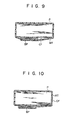
- the thermal adhesive tape MT may be wound around the stack of bank notes P with the coating layer CF outward so that the turnup portion BP is formed at the cut end portion of the tape MT.
- the bank notes may be aligned by any other suitable means.
- the backup plate 3 In lowering the backup plate 3 of Fig. 1 to transfer the stack of bank notes thereon to the carrier 8, the backup plate 3 may first be lowered from the upper position A O to the position Al of Fig. 1. Then, the carrier 8 is moved to the right of Fig. 1 to bring the back plates 13a, 13b and 13c of the carrier 8 into contact with the stack of bank notes on the backup plate 3, thereby aligning or truing up the bank notes. Immediately after this, the backup plate 3 is lowered to the lower position A 2 to transfer the stack of sheets entirely to the carrier 8.
- the motion of the carrier and the catcher are physically interlocked by their mechanical arrangement.
- an independent drive mechanism may be provided so that the carrier and the catcher are operated synchronously under electronic control.
- one end portion of a band material coated on one side with a thermally fusible material is turned up so that the band material may be thermally bonded at the turnup portion.
- the heater pad which is essential to the prior art apparatus, is obviated in the present invention, and the objects to be bundled can be bundled with a higher reliability.
- Figs. 11 to 13D a bundling apparatus according to the other embodiment of the present invention will be described.
- like reference numerals are used to designate like portions described in connection with the foregoing embodiment.
- the other embodiment uses bundle removal mechanism 126 which is different in construction from the bundle removal mechanism or scraper 26 used in the one embodiment.
- the bundle removal mechanism 126 is mounted on the base (not shown) so as to be located under the carrier 8 in the carrier home position CRHP.
- the bundle removal mechanism 126 is provided with a removal lever 126A whose front end (or right end portion as illustrated) is bent and nested in the beds 13A to 13C.
- the removal lever 126A can rock around support holders 126B.
- the rear end portion of the removal lever 126A is urged by an urging member 126C so that the removal lever 126A is rocked in the counterclockwise direction of Fig. 11.
- Stoppers 126D are located between the holders 126B and the urging member 126C to restrict the stopping position of the removal lever 126A.
- the removal lever 126A is so set that, when no external force is applied to it, its front end portion is located on the right end side of the carrier 8 in the carrier home position CRHP and in the path of travel of the carrier 8. Further, the removal lever 126A is so designed that, when the backup plate 3 is lowered, it abuts against the front end portion of the removal lever 126A to rock the lever 126A in the clockwise direction in Fig. 11 so that the front end portion of the lever 126A is located below the upper surfaces of the beds 13A to 13C.
- the carrier 8 is on stand-by in the carrier home position CRHP when a specified number of bank notes P are put on the backup plate 3.
- the removal lever 126A is on stand-by in the path of travel of the carrier 8, having its front end portion nested with the carrier 8.
- the backup plate 3 descends, the lower surface of the backup plate 3 abuts against the front end portion of the removal lever 126A to rock the lever 126A clockwise against the urging force of the urging member 126C.
- the backup plate 3 passes by the beds 13A to 13C of the carrier 8 in the nested manner to transfer the stack of bank notes P thereon to the beds 13A to 13C of the carrier 8, as shown in Fi g . 13B.
- the motor 18 is driven in the clockwise direction of Fig. 11 to move the carrier 8 and the catcher 72 in an interlocked manner.
- the carrier 8 and the catcher 72 move in the manner described in the one embodiment with reference to Figs. 8A to 8F. That is, the carrier 8 transfers the stack of bank notes P directly to the bundling mechanism 2 (see Figs. 8B and 8C).
- the catcher 72 rotates gradually to wind the band material around the stack of bank notes P.
- the backup plate 3 is elevated to accept another stack of bank notes P to be bundled subsequently.
- the removal lever 126A which has so far been abutting against the backup plate 3, follows the rising backup plate 3 to be rocked by the urging force of the urging member 126C.
- the rocking of the removal lever 126A is restricted by the stoppers 126D.
- the removal lever 126A is returned to the position shown in Fig. 13A.
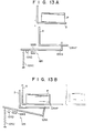
- the carrier 8 is nested with the front end portion of the removal lever 126A when it reaches a position just short of the carrier home position CRHP. Then, the bundle P' on the carrier 8 abuts against the front end portion of the removal lever 126A to be restrained from moving, as shown in Fig. 13C. As the carrier 8 gradually approaches the carrier home position CRHP, the bundle P' is dropped from the carrier 8 into the chute 27 thereunder, as shown in Fig. 13D. Then, the carrier 8 is transferred to the carrier home position CRHP, and one cycle of operation is completed.
- the bundle removal mechanism 126 By the use of the bundle removal mechanism 126, the bundle can be easily and reliably removed, and it is possible to obviate the need for the backward movement of the carrier which is required in the one embodiment by the scraper 26 (which is nested in the carrier and engages the bundle delivered thereto to drop the same from the carrier) fixed behind the carrier home position CRHP.
- the apparatus may be made more compact.
- the opposite faces of the clamp lever 104 and the beds 13A to 13C of the carrier 8 carrying the stack of bank notes P are flat.
- the present invention is not limited to this arrangement.
- the opposite faces of the clamp lever 104 and the bed 13A (or 13B or 13C) may be curved in the same direction.
- the stack of bank notes P is bundled in the manner shown in Figs. 15A and 15B.
- the bank notes can be bundled securely, and the bundle P ' can be prevented from collapsing.
- it is unnecessary to use pressure-holding belts (a pair of belts with gradually narrowed opposite faces) which have conventionally been required for an increased bundling strength.
- the bundling strength can be increased using of a very simple construction.
- the removal lever 126A in the second embodiment is described as being of a rocking type. Alternatively, however, the removal lever 126A may be so constructed as to slide vertically under the carrier home position CRHP. Also, the removal lever 126A may be so designed as to be moved out of the path of travel of the transfer means when it abuts against the objects to be bundled.
Abstract
Description
- The present invention relates to a bundling apparatus for collectively bundling objects to be bundled stacked in a pile, and more specifically, to a bundling apparatus in which a band material is wound around objects to be bundled and both ends of the band material are bonded together to securely bundle the objects.
- Prior art bundling apparatuses of this type have a band material passed along a guide member to form a loop, through which objects to be bundled, such as a stack of sheets, are inserted. After the guide member is drawn out of the looped band material, the band material is tightened and both its end portions are joined and thermally welded together to bundle the stack of sheets.
- In these conventional bundling apparatuses, however, the width or diameter of the guide member must be greater than the width of the stack of sheets to be bundled. As a result, the size of the apparatus is increased. If the guide member is circular in shape, the width of the sheets inserted therein must be less than the diameter of the guide member. Thus, the apparatus cannot be well adapted to sheets of different widths. If the guide member is formed of guide bars facing each other, it requires a guide bar transfer mechanism for improved adaptability to the sheet width, thus complicating the construction of the apparatus.
- The present invention has been developed in consideration of these circumstances, and is intended to provide a bundling apparatus which is improved in adaptability to the size of objects to be bundled and which is also compact in design.
- According to an aspect of the present invention, there is provided a bundling apparatus which comprises: transfer means for receiving stacked objects to be bundled and transferring the same along a prescribed path of travel; and bundling means for bundling the objects to be bundled transferred thereto by the transfer means, said bundling means including winding means for winding a band around the objects to be bundled so that one end of the band is joined with another portion of the band, and bonding means for bonding together the joined end portions of the band wound around the objects to be bundled, said transfer means including a carrier bearing thereon the objects to be bundled and capable of moving between a first position where the carrier receives thereon the objects to be bundled and a second position inside the winding means, and first driving means for moving the carrier from the first position to the second position after the objects to be bundled are set on the carrier, and then moving the carrier from the second position to the first position, said winding means including a catcher retaining the one end of the band and capable of moving across the path of travel, the catcher being moved along a line of movement including a third position below the objects to be bundled on the carrier and a fourth position above the objects to be bundled, the line of movement lying between the first and second positions, and second drive means for moving the catcher from the third position to the fourth position before the carrier moved from the first position toward the second position by the first driving means crosses the line of movement, moving the catcher from the fourth position to the third position after the carrier crosses the line of movement, thereby winding the band around the objects to be bundled, and then moving the catcher from the third position to a fifth position defined between the third and fourth positions, thereby joining the one end of the band with the other portion of the band.
- The present invention provides a bundling apparatus characterized in that both the carrier to transfer the objects to be bundled and the catcher retaining the bundling band and revolving in the object transfer direction are driven relatively so that the band is wound around the objects while they are being transferred.
- This invention can be more fully understood from the following detailed description when taken in conjunction with the accompanying drawings, in which:
- Fig. lA is a front view of a transfer mechanism of a bundling apparatus according to one embodiment of the present invention;
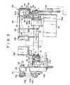
- Fig. 1B is a front view of a bundling mechanism of the bundling apparatus;
- Fig. 2 is a plan view collectively showing the bundling apparatus shown in Figs. lA and 1B;
- Fig. 3 is a right side view of the bundling apparatus;
- Fig. 4A is a right side view of a winder of the bundling mechanism;
- Fig. 4B is a perspective view showing the distal end portion of a catcher;
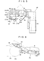
- Fig. 5 is a rear view of the winder;
- Fig. 6 is a front view of a retaining lever mechanism;
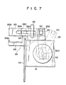
- Fig. 7 is a left side view of an open/pull drive mechanism;
- Figs. 8A to 8F are front views individually showing steps in a bundling operation;
- Fig. 9 is a sectional view showing a bundled object bundled by the bundling apparatus;
- Fig. 10 is a sectional view showing a first modification of the bundle;
- Figs. 11 and 12 are a front view and a plan view, respectively, showing bundle removal means used in a bundling apparatus according to the other embodiment of the invention;
- Figs. 13A to 13D are front views illustrating several operating steps of the other embodiment;
- Figs. 14A and 14B are front views showing second and third modifications, respectively, of the bundling apparatus according to the invention; and
- Figs. 15A and 15B are sectional views showing bundles provided by the use of the second and third modifications, respectively.
- A bundling apparatus according to one embodiment of the present invention will now be described in detail with reference to the accompanying drawings.
- The bundling apparatus serves to bundle objects to be bundled, e.g., a stack of bank notes, and mainly comprises a
transfer mechanism 1 and abundling mechanism 2. - In Figs. lA and 1B,
numeral 3 designates a backup plate which carries thereon and vertically transfers a specified number of bank notes stacked by a stacking apparatus (not shown). Thetransfer mechanism 1 receives the bank notes which are lowered on thebackup plate 3 as thebackup plate 3 descends and then delivers them to thebundling mechanism 2. - The construction of the
transfer mechanism 1 will first be explained. As shown in Figs. 2 and 3, the bundling apparatus comprises a pair ofside frames transfer mechanism 1 is attached to theseside frames guide rod 6 extends parallel to the oneside frame 4A, and is supported at both ends by brackets 5 (Fig. 2) attached to the lateral side of the oneside frame 4A. Aguide rail 7 is attached to theother side frame 4B, facing theguide rod 6. Acarrier 8 is provided between theguide rail 7 and theguide rod 6 so as to be movable along them. - The
carrier 8 includes aframe 9 which is substantially U-shaped in a two-dimensional configuration. A plurality ofguide rollers 10 in rolling contact with theguide rail 7 are rotatably attached to one lateral portion of theframe 9. Attached to the other lateral portion of theframe 9 is aside bracket 12 withpinch rollers 11 to hold theguide rod 6 from both upper and lower sides. Theside bracket 12 is fitted with afirst bed 13A having a cut portion and extending horizontally. Second andthird beds frame 9 by means of anintermediate bracket 14. The second andthird beds first bed 13A. The space between the first andsecond beds gap portion 13D located in the position where the band is wound by a catcher 72 (to be mentioned later). Thebeds 13A to 13C of thecarrier 8 and thebackup plate 3 are nested into each other. Accordingly, thebackup plate 3 can descend from an upper position AO to a lower position A2 below thebeds 13A to 13C via an intermediate position A1 substantially flush with thebeds 13A to 13C, as shown in Figs. lA and 1B. - A
carrier driver 15 is provided to move thecarrier 8 along theguide rod 6. Thecarrier driver 15 has astay 19 which is fixed to theside frames stay 19 is fitted with areversible motor 18 having adrive sprocket 17A. Thedrive sprocket 17A faces one end of the oneside frame 4A. Anidle sprocket 17B is rotatably attached to the other end of the oneside frame 4A. Anendless chain 20 is stretched between the twosprockets piece 21 and anengaging roller 22 are attached by means of alink holder 23 to one of links (not shown) constituting thechain 20. Theside bracket 12 of thecarrier 8 is fitted with atransmission member 24 having acut portion 24A in which the engagingroller 22 is fitted. Thecarrier 8 constructed in this manner can move in the longitudinal direction following the movement of thechain 20 through the medium of the engagingroller 22 and thetransmission member 24. - With this arrangement, as the
backup plate 3 descends, thecarrier 8 receives the bank notes from thebackup plate 3 in a carrier home position CRHP, indicated by a solid line in Figs. lA, 1B and 2. After receiving the bank notes, thecarrier 8 is transferred by thecarrier driver 15 to a carrier stop position CRSP indicated by a one dot and dashed line in Figs. lA, 1B and 2, where the bank notes are bundled by thebundling mechanism 2. Thereafter, as themotor 18 is reversed, thecarrier 8 is moved back to a carrier back position CRBP indicated by two-dots and dashed line in Figs. lA, 1B and 2. Then, themotor 18 is rotated in the forward direction, so that thecarrier 8 is returned to the carrier home position CRHP. Thus, one cycle of movement for thecarrier 8 is completed. - Between the carrier home position CRHP and the carrier back position CRBP, a scraper as a
bundle removal mechanism 26 is fixedly attached to the base (not shown). Thescraper 26 is nested with thebeds 13A to 13C of thecarrier 8, and abuts against a bundle of the bank notes (hereinafter referred to simply as a bundle) on thecarrier 8. Accordingly, while thecarrier 8 is moving from the carrier stop position CRSP to the carrier back position CRBP, the bundle on thecarrier 8 engages thescraper 26 to be prevented from moving, and then drops from thecarrier 8. Thus, the bundle can be delivered to some subsequent process (not described) by way of achute 27 under thescraper 26. The use of thescraper 26 enables the bundle to be removed securely from thecarrier 8 by a very simple structure. - The
carrier 8 is further provided with anauxiliary clamp mechanism 29 for preventing the stack of bank notes on thebeds 13A to 13C from collapsing during transfer. Theauxiliary clamp mechanism 29 also serves to orient the bank notes delivered from thebackup plate 3 onto thecarrier 8 in the longitudinal direction (i.e., the bank notes are laid on thecarrier 8 so that their longitudinal direction is at right angles to the moving direction of the carrier 8). As shown in Figs. 2 and 3, one end portion of aclamp bracket 30 is attached to theframe 9 of thecarrier 8. Arod 31 is vertically passed through the other end portion of theclamp bracket 30. Aclamp holder 32 with a substantially U-shaped cross section is pivotally mounted on therod 31 so as to be rockable around therod 31. Aclamp plate 33 lies over theclamp holder 32 and is swingable around ahinge 32A within a vertical plane. Afirst cam follower 35 rotatable on a horizontal axis is attached to the proximal end portion of theclamp plate 33 by means of astud 34. A curved aligningrod 36 is attached to the distal end portion of theclamp plate 33. When theclamp holder 32 is rocked in the clockwise direction of Fig. 2, the aligningrod 36 is located between the second andthird beds - A
second cam follower 37 rotatable on a vertical axis is attached to the lower end portion of theclamp holder 32. Fixed on theother side frame 4B is a fixedcam block 38 which engages the first andsecond cam followers cam block 38 is formed of an L-shaped channel bar, comprising afirst cam face 38A at the upper surface portion (Fig. 3) to allow for the vertical swinging of theclamp plate 33 and asecond cam face 38B at the lateral face portion (Fig. 3) for the horizontal rocking of theclamp holder 32. The right end portion (Fig. 2) of thefirst cam face 38A is rounded and bent downward and the remaining portion thereof is straight. Therefore, when thefirst cam follower 35 reaches the right end portion of thefirst cam face 38A, it comes down to cause theclamp plate 33 to swing counterclockwise (Fig. 3) around thehinge 32A. The right end portion (Fig. 2) of the second cam face 28B is rounded and bent inward and the remaining portion thereof is straight. Therefore, when thesecond cam follower 37 reaches the right end portion of thesecond cam face 38B, it moves inward to cause theclamp holder 32 to rock clockwise (Fig. 2) around therod 31. The right end portion of thefirst cam face 38A is located on the right (Fig. 2) of the right end portion of thesecond cam face 38B. Theclamp holder 32 is urged to rock clockwise (Fig. 2) by an urging member (not shown). - In such a state that the
carrier 8 is located between the carrier home position CRHP and the carrier back position CRBP, thesecond cam follower 37 is pushed by the straight portion of thesecond cam face 38B, so that theclamp plate 33 is located in the position indicated by the solid line in Fig. 2. In other words, theclamp plate 33 is removed from the region over the first to third beds, 13A to 13C. In this state thefirst cam follower 35 lies on the straight portion of thefirst cam face 38A, so that theclamp plate 33 is kept substantially horizontal, as indicated by the solid line in Fig. 3. In other words, theclamp plate 33 is held above the stack of bank notes laid on the first tothird beds 13A to 13C. As thecarrier 8 is moved gradually from the carrier home position CRHP to the carrier stop position CRSP of Fig. 2, thesecond cam follower 37 is disengaged from thesecond cam face 38B and then thefirst cam follower 35 is disengaged from thefirst cam face 38A, at the right end portions thereof, so that theclamp plate 33 gradually swings clockwise (Fig. 3) around therod 31, urged by the urging member (not shown), thereafter, theclamp plate 33 gradually swings counterclockwise (Fig. 3) around thehinge 32A. Thus, the aligningrod 36 at the distal end of theclamp plate 33 engages the longitudinal edges of the bank notes on thebeds 13A to 13C, and pushes the bank notes to backportions 13a to 13c of thebeds 13A to 13C to align or true up the bank notes. After this alignment, the distal end portion of theclamp plate 33 presses on the top of the stack of bank notes trued up by the aligningrod 36, thereby preventing the stack of bank notes from collapsing during the transfer. - The
auxiliary clamp mechanism 29 has an aligning function. Accordingly, no trouble will be caused if thecarrier 8 in the carrier home position CRHP is subject to errors in location so that the position of the stack of bank notes on thecarrier 8 is deviated. Even though the bank notes on thebeds 13A to 13C vary in width, moreover, it is unnecessary to change the carrier home position CRHP and the position of the stacking device including thebackup plate 3. Thus, the apparatus of the present invention can enjoy improved applicability to bank notes of varied widths. Since the bank notes are aligned during the transfer of thecarrier 8, the processing speed of the apparatus may be increased. - Now the construction of the
bundling mechanism 2 will be explained. Thebundling mechanism 2 comprises afeeder 40 for supplying a band material coated on one side with a thermally fusible material, e.g., a thermal adhesive tape MT with a coating layer CF on the lower surface as in Fig. 1B, awinder 41 for winding the thermal adhesive tape MT from thefeeder 40 around the stack of bank notes delivered thereto by thecarrier 8, amain clamp mechanism 42 for compressing and holding the stack of bank notes wound with the thermal adhesive tape MT by thewinder 41, and aheat bonding mechanism 43 for thermally bonding the thermal adhesive tape MT around the stack of bank notes. Thewinder 41 includes a turning mechanism 41A for turning up one end portion of the wound tape MT. - A
stay 45 is stretched between the twoside frames feeder 40 is attached to the substantially central portion of thestay 45 so that it may be located in thegap portion 13D between the first andsecond beds carrier 8 is positioned as shown in Fig. 2. As shown in Fig. 1B, afeeder bracket 46 is attached to thestay 45. One end portion of apinch roller holder 47 is pivotally mounted on thefeeder bracket 46 so that thepinch roller holder 47 can rock around ashaft 47A. Apinch roller 48 is rotatably supported on the other end portion of thepinch roller holder 47. Afeed roller 49 is mounted on adrive shaft 50 so as to be in contact with thepinch roller 48. An urging member, e.g., aleaf spring 51, is attached to the one end portion of thepinch roller holder 47. The distal end portion of theleaf spring 51 engages the tip portion of an adjustscrew 52 attached to thefeeder bracket 46. The contact pressure of thepinch roller 48 on thefeed roller 49 may be finely adjusted by turning the adjustscrew 52. The thermal adhesive tape MT is held between thepinch roller 48 and thefeed roller 49, and is fed as thefeed roller 49 rotates in the clockwise direction of Fig. 1B and returned as thefeed roller 49 rotates in the counterclockwise direction. - On the down stream side of a tip portion between the
feed roller 49 and thepinch roller 48, with respect to the feeding direction of the thermal adhesive tape MT, lie a fixedcutting edge 53A and amovable cutting edge 53B which reciprocates along the fixedcutting edge 53A in accordance with the operation of arotary solenoid 54. Aguide plate 55 and aguide roller 56 for guiding the thermal adhesive tape MT are arranged on the down stream side of thecutting edges - As shown in Fig. 3, a
drive mechanism 49A for thefeed roller 49 comprises an electromagnetic clutch/brake 57 attached to the middle portion of thedrive shaft 50, anidle gear 58 mounted on the other end portion of thedrive shaft 50, adrive gear 59 in mesh with theidle gear 58, and afeed motor 60 for rotating thedrive gear 59. Thefeed motor 60 is a reversible motor, and it is reversed after the thermal adhesive tape MT is moved around the bank notes by thewinder 41. The wound thermal adhesive tape MT is supported in the middle by theguide roller 56, and so is pulled back as thefeed roller 49 rotates in the counterclockwise direction of Fig. 2. Thus, the bank notes are bound tight. - Now the construction of the
winder 41 will be described. As shown in Fig. 2, abearing block 65 containing therein a radial bearing (not shown) and other members is attached to the oneside frame 4A in the vicinity of the carrier stop position CRSP. Adrive shaft 66 is rotatably fitted in thebearing block 65 to be supported thereby. Astop collar 67 and astop plate 68 are attached, respectively, to the proximal part and the distal end part of that portion of thedrive shaft 66 which projects inside the oneside frame 4A. Thestop collar 67 and thestop plate 68 can rotate together with thedrive shaft 66. Between thestop collar 67 and thestop plate 68, aguide shaft 69 extends parallel to thedrive shaft 66. Thedrive shaft 66 and theguide shaft 69 constitute anarrow guide 70. A slidingblock 71 is fitted in thenarrow guide 70 so as to be slidable along theshafts stop collar 67 and thestop plate 68. The stroke of the slidingblock 71 is longer than the width of the thermal adhesive tape MT. The slidingblock 71 is provided with thecatcher 72 to hold the thermal adhesive tape MT supplied from thefeeder 40. - Figs. 4A and 5 show the
catcher 72 in detail. Thecatcher 72 includes a platelikefixed catcher member 72A screwed to the slidingblock 71, and a platelike swingingcatcher member 72B swingably attached to the slidingblock 71 and capable of being joined with the fixedcatcher member 72A. An L-shapedrocking hook portion 72C is formed at the proximal end portion of the swingingcatcher member 72B. By pulling the rockinghook portion 72C to the left of Fig. 4A, the swingingcatcher member 72B is separated from the fixedcatcher member 72A at a given angle. As shown in Fig. 5, ahook lever 73 is attached to that portion of the slidingblock 71 which forms an angle of approximately 90° around thedrive shaft 66 with the rockinghook portion 72C. When thehook lever 73 is pulled to the left of Fig. 4A, the slidingblock 71 is moved to the left, so that thecatcher 72 is taken out of the range of travel of the thermal adhesive tape MT. Namely, thecatcher 72 is disengaged from the thermal adhesive tape MT. Thehook lever 73, along with thecatcher 72 and thehook portion 72C, can revolve around thedrive shaft 66 as theshaft 66 rotates, while keeping the relative positions shown in Fig. 5. Here afixed angle 6 is kept between a plane including thedrive shaft 66 and thecatcher 72, and an extending surface of thecatcher 72. This special arrangement constitutes the turning mechanism 41A. - On the opposite faces of the distal end portions of the fixed and swinging
catcher members tape holding portions 72D (Fig. 4B) are formed with a plurality of ridges extending along the extending direction of thecatcher 72, that is, at right angles to the tape winding direction. Thus, the thermal adhesive tape MT is prevented from slipping off from thecatcher 72 when thecatcher 72 holding the tape MT is rotated. When thecatcher 72 is moved to the left in Fig. 4A, it can readily be removed from the thermal adhesive tape MT. - A
catcher driver 75 is attached to the oneside frame 4A. Thecatcher driver 75 serves to rotate thecatcher 72 as thedrive shaft 66 rotates. As shown in Fig. 1B, thecatcher driver 75 comprises afirst gear 75A to rotate together and coaxially with theidle sprocket 17B, asecond gear 75B in mesh with thefirst gear 75A, athird gear 75C to rotate together and coaxially with thesecond gear 75B, and afourth gear 75E coaxially fixed to one end of thedrive shaft 66. A rotatary force is transmitted from thethird gear 75C to thefourth gear 75E by means of atiming belt 75D which is stretched between thethird gear 75C andfourth gear 75E. Thus, thecatcher driver 75 is driven by the same drive source (motor) 18 with thecarrier dirver 15. Accordingly, thecatcher 72 rotates interlocking with the movingcarrier 8. - Namely, the
catcher 72 holding the forward end portion of the thermal adhesive tape MT gradually rotates in the counterclockwise direction of Fig. 1B while thecarrier 8 moves from the carrier home position CRHP to the carrier stop position CRSP, as shown in Fig. 1B. Thus, the bank notes on thecarrier 8 are gradually wound with the thermal adhesive tape MT. Therefore, the radius of gyration of thecatcher 72 can be made shorter than the width of the bank notes. According to the prior art mechanism, the thermal adhesive tape must be pulled around a stack of bank notes at a standstill. It is therefore necessary that the radius of gyration of the conventional catcher be longer than the width of the stack of bank notes. In this embodiment, the radius of gyration of thecatcher 72 need only be longer than the height of the stack of bank notes, theoretically. By the use of thewinder 41 of the aforementioned construction, it is unnecessary to change the radius of gyration of thecatcher 72 even if the bank notes vary in width. Thus, thewinder 41 can be made compact and improved in applicability to the bank note width. When exporting the bundling apparatus (to be used, for example, as a bank note bundling apparatus), therefore, it is unnecessary to change or readjust the apparatus according to the width of bank notes or bills used in the importing country. For example, a Japanese 10,000-yen note is 84 mm wide; a U.S. dollar is 66 mm wide, a United Kingdom 10-pound note is 85 mm wide, a West German 100-mark note is 80 mm wide, a French 100-franc note is 92 mm wide, an Austrian 1,000-schilling note is 84 mm wide, a Dutch 100-guilder note is 76 mm wide, and an Italian 10,000-lira note is 78 mm wide. The bundling apparatus of the present one embodiment can bundle all these sizes of bank notes without any remodeling. - As described before, the
catcher 72 does not rotate relative to the slidingblock 71, but revolves in one with the slidingblock 71 around thedrive shaft 66. Therefore, when the thermal adhesive tape MT held by thecatcher 72 is moved around the stack of bank notes, the forward end portion of the thermal adhesive tape MT projecting from the distal end portion of thecatcher 72 is turned up so that the coating layer CF with the fusible material faces inside. Thus, a turnup portion BP is formed on the forward end portion of the thermal adhesive tape MT. The coating layer CF of the turnup portion BP is opposed to the coating layer CF of the thermal adhesive tape MT. Even through the turnup portion BP is heated, therefore, the fusible material will never stick to the bank notes. Thus, theheat bonding mechanism 43 heats that portion of the thermal adhesive tape MT which is joined with the turnup portion BP. - The respective motions of the
carrier 8 and thecatcher 72, in particular, are physically interlocked by mechanical means. Accordingly, it is possible to completely prevent timing errors attributed to electrical noise or interference between the movement of thecatcher 72 and the rotation of thecarrier 8. Referring now to Fig, 1B, the interlocking timing of thecatcher 72 and thecarrier 8 will be described. When thecarrier 8 is in the carrier home position CRHP, thecatcher 72 is located in a catcher home position CTHP indicated by a solid line in Fig. 1B. At this time, the engagingroller 22 attached to thechain 20 is located in a roller home position RHP indicated by a solid line in Fig. 1B. When thecarrier 8 reaches the carrier stop position CRSP, the engagingroller 22 is brought to a roller separation position RTOP indicated by a two-dots and dash line on theidle sprocket 17B. At this time, thecatcher 72 is located in a catcher intermediate position CTIP over the stack of bank notes, as indicated by a one dot and dash line in Fig. 1B. When the engagingroller 22 reaches a first reverse position 1st RP beyond the roller separation position RTOP, thecatcher 72 passes through the catcher home position CTHP to reach a catcher seal position CTSP indicated by a two-dots and dash line in Fig. 1B. - When the engaging
roller 22 moves between the roller separation position RTOP and the first reverse position 1st RP, it is disengaged from thetransmission member 24. Accordingly, thecarrier 8 does not move, and only thecatcher 72 rotates. Themotor 18 is rotated in the reverse direction to move the engagingroller 22 to a second reverse position 2nd RP behind the roller home position RHP. Then, themotor 18 is rotated again in the forward direction to move the engagingroller 22 to the roller home position RHP. Thus, thecarrier 8 is returned to the carrier home position CRHP. When thecatcher 72 is in the catcher home position CTRP as indicated by a two-dots and dash line in Fig. 5, the slidingblock 71 assumes a first stop position 1st SP. When thecatcher 72 is in the catcher seal position CTSP, the slidingblock 71 takes a second stop position 2nd SP as indicated by a solid line in Fig. 5. - To secure such interlocking timing, a carrier retaining mechanism is provided which holds the
carrier 8 when the engagingroller 22 moves between the roller separation position RTOP and the first reverse position 1st RP to rotate only thecatcher 72. As shown in Fig. 1B, the carrier retaining mechanism is provided with amagnet block 78 which magnetically attracts and holds thecarrier 8 in the carrier stop position CRSP. As shown in Figs. 2 and 6, the carrier retaining mechanism further includes a retaininglever mechanism 79 disposed near theidle sprocket 17B. The retaininglever mechanism 79 has astud 80 attached to the inner surface of the oneside frame 4A. A retaininglever 81 is swingably attached to thestud 80 so as to be able to engage the engagingroller 22 moving together with thechain 20. The retaininglever 81 is urged in the counterclockwise direction of Fig. 6 by an urging member (not shown), and kept inclined, as indicated by a solid line in Fig. 6. Abent hook portion 81A is formed at the right end portion (Figs. 2 and 6) of the retaininglever 81. When thecarrier 8 is moved to the carrier stop position CRSP, thehook portion 81A slips into agroove 82A of astopper 82 attached to the lateral portion of thecarrier 8. As the engagingroller 22 moving with thechain 20 engages the left end portion of the retaininglever 81, the regaininglever 81 is gradually swung clockwise (Fig. 6) against the urging force of the urging member (not shown). Immediately after thecarrier 8 reaches the carrier stop position CRSP to cause the engagingroller 22 to be disengaged from thetransmission member 24, the engagingroller 22 reaches acut portion 81B at the middle portion of the retaininglever 81. Accordingly, the retaininglever 81 is swung counterclockwise (Fig. 6) by the urging force of the urging member, so that thehook portion 81A is fitted in thestopper 82 of thecarrier 8 to position thecarrier 8 in place. This carrier retaining mechanism prevents thecarrier 8 from being dislocated even if the thermal adhesive tape MT is tightened after it is wound around the stack of bank notes. Thus, the timing of the interlocking between thecarrier 8 and thecatcher 72 can be maintained with high reliability. - The
catcher 72 is opened to receive the thermal adhesive tape MT in the catcher home position CTHP. When in the catcher seal position CTSP, thecatcher 72 is pulled downward as in Fig. 2 (or to the left in Fig. 4) to be disengaged from the bundle. To perform these actions of thecatcher 72, an open/pull driver 85 is attached to the oneside frame 4A, as shown in Fig. 2. Fig. 5 shows the back of the open/pull driver 85, and Fig. 7 is a left side view showing part of the open/pull driver 85. - As shown in Fig. 2, the open/
pull driver 85 has alever holder 86 which is L-shaped in plane configuration and attached to the oneside frame 4A. Two guide rollers 87 (only one is shown in Fig. 2) are arranged side by side on thelever holder 86 at right angles to the feeding direction of the bank notes. Anopen lever 88 having aslot 88A and apull lever 89 having aslot 89A are reciprocatively supported by theguide rollers 87 so that theguide rollers 87 are fitted in theslots lever hook portion 89B is formed which can engage thehook lever 73 attached to the slidingblock 71. As thehook portion 89B engaging thehook lever 73 is pulled to the right in Fig. 7, therefore, the slidingblock 71 is pulled in a like manner, and thecatcher 72 is disengaged from the thermal adhesive tape MT. Aguide roller 90 is rotatably attached to the other end portion of thepull lever 89. At one end portion of theopen lever 88 an openlever hook portion 88B is formed which can engage thehook portion 72C formed on the swingingcatcher member 72B. As thehook portion 88B engaging the hook portion 82C is pulled to the right of Fig. 7, therefore, the swingingcatcher member 72B is swung in a clockwise direction in Fig. 4A, so that thecatcher 72 is opened. An abutting portion 88C to abut against the pulllever hook portion 89B is formed at the middle portion of theopen lever 88. - A
rotary solenoid 92 is attached to the oneside frame 4A by means of asolenoid holder 91. One end portion of a rockinglever 93 is fixed to asolenoid shaft 92A of therotary solenoid 92. At the other end portion of the rocking lever 93 acut portion 93A is formed which engages theguide roller 90 attached to the other end portion of thepull lever 89. Thus, thepull lever 89 reciprocates as the rockinglever 93 rocks, and theopen lever 88 moves when the pulllever hook portion 89B abuts against the abutting portion 88C of theopen lever 88. Theopen lever 88 is urged to the left of Fig. 7 by an urging member (not shown). As shown in Fig. 5, theopen lever 88 and thepull lever 89 are arranged at a given angle to each other. - When the
catcher 72 is in the catcher home position CTHP, as indicated by a two-dots and dash line in Fig. 5, thehook portion 72C of thecatcher 72 is located in such a position that it can engage the openlever hook portion 88B. If therotary solenoid 92 is then actuated, only the opening of thecatcher 72 can be achieved. In any other position than the catcher home position CTHP, thecatcher 72 is closed. When thecatcher 72 is in the catcher seal position CTSP, as indicated by a solid line in Fig. 5, thehook lever 73 attached to the slidingblock 71 is located in the position to engage the pulllever hook portion 89B. If therotary solenoid 92 is then actuated, the slidingblock 71 can be moved along thedrive shaft 66. - As shown in Figs. 2 and 7, a sensor, e.g. a
photosensor 95, for checking the operation of the open/pull driver 85 is provided at the middle portion of thelever holder 86. A detectedplate 96 to be detected by thesensor 95 is attached to the rockinglever 93. When the abutting portion 88C of theopen lever 88 moves in contact with the pulllever hook portion 89B of thepull lever 89, the extreme end of the detectedplate 96 is disengaged from thesensor 95. In this manner, thesensor 95 checks the open/pull driver 85 for operation. With this arrangement, thesingle rotary solenoid 92 can serve both to insert the thermal adhesive tape MT in thecatcher 72 and to disengage thecatcher 72 from the bundle. Moreover, the operation check can be achieved by the use of thesingle sensor 95. - The
main clamp mechanism 42 is constructed as shown in Figs. 1B and 2. One end portion of a horizontally extendingclamp bracket 100 is attached to the right end portion (Fig. 2) of the oneside frame 4A. Two vertically extendingguide plates 101 arranged parallel to each other with aprop 102 between them are fixed to the other end portion of theclamp bracket 100. Theguide plates 101 have theirrespective guide slots 101A extending along their longitudinal direction. A pair of clamp levers 104, each having twoguide rollers 103 at one end portion to be fitted in theguide slot 101A of eachguide plate 101, extend to the left in Fig. 2 so that the twoguide plates 101 are sandwiched between the clamp levers 104. Thus, the clamp levers 104 can move along theircorresponding guide slots 101A. The twoclamp levers 104 are coupled by means of ashaft 105 and thus can move as a body. The clamp levers 104 are arranged in such positions that they do not come into contact with either the thermal adhesive tape MT wound around the stack of bank notes on thecarrier 8 or with theclamp plate 33. - A
clamp lever driver 106 is provided for moving the clamp levers 104. Theclamp lever driver 106 comprises abearing 107 at the intermediate portion of theclamp bracket 100, adrive shaft 108 rockably supported by thebearing 107, acam lever 109 fixed to one end of thedrive shaft 108 and having acut portion 109A to engage theshaft 105, acam follower lever 110 fixed to the other end of thedrive shaft 108 and having acam follower 110A, aclamp motor 111 having acam 111A to engage thecam follower 110A, and an urging member (not shown) to bring thecam follower 110A into close contact with the outer peripheral surface of thecam 111A. Thus constructed, theclamp lever driver 106 can reciprocate the clamp levers 104 along theguide slots 101A by means of thecam lever 109 which rocks as thecam 111A rotates. - The
heat bonding mechanism 43 is constructed as shown in Figs. 1B and 2. Aheat bonding bracket 115 is attached to theother side frame 4B. Aguide base 117 is attached to theheat bonding bracket 115 by means of ablock 116, extending parallel to theside frame 4B. Theguide base 117 is fitted with two pairs ofguide rollers 118 arranged along the tape feeding direction and facing one another. Aslide base 119 is held between theguide rollers 118 for reciprocation. Aheater block 121 is mounted on theslide base 119 by means of aholder 120. Theheater block 121 is rockably attached to theholder 120. Theheater block 121 is urged in the clockwise direction of Fig. 1B by an urging member (not shown), and is kept by a stopper (not shown) in the position indicated by a solid line in Fig. 1B. When theslide base 119 moves upward (Fig. 1B), theheater block 121 abuts against that portion of the thermal adhesive tape MT around the stack of bank notes on thecarrier 8 which is joined with the turnup portion BP. Thereafter, theheater block 121 rocks counterclockwise (Fig. 1B) against the urging force of the urging member to assume the position indicated by a two-dots and dash line in Fig. 1B. - A heater block drive mechanism 128 is formed of a
guide roller 122 mounted on the intermediate portion of theslide base 119, a rockinglever 123 having, at one end portion, a cut portion to engage theguide roller 122 and, rockably mounted on theheat bonding bracket 115 at the other end portion, acrank lever 124 having aslider 124A to engage a slot in the middle portion of the rockinglever 123, and adrive motor 125 for rotating thecrack lever 124. Thus, theheater block 121 is reciprocated by actuating thedrive motor 125. - As shown in Fig. 1B, a
tape stopper 126 formed of, e.g., a leaf spring, is rockably disposed between the twoguide plates 101. Anonskid rubber plate 127 is attached to the upper surface of thetape stopper 126. Thetape stopper 126 rocks as theheater block 121 moves. Namely, thetape stopper 126 presses the thermal adhesive tape MT against the stack of bank notes P before the heat bonding operation by theheater block 121, thereby preventing the tape MT from slackening when cut by thecutting edges feeder 40. - Referring mainly to Figs. 8A to 8F, the operation of the bundling apparatus of the aforementioned construction will now be described.
- When the
carrier 8 is in the carrier home position CRHP, as shown in Fig. 8A, thebackup plate 3 is lowered so that the stack of bank notes P on thebackup plate 3 is transferred to thebeds 13A to 13C of thecarrier 8. At this time, thecatcher 72 is in the catcher home position CTHP. Namely, thehook portion 72C of thecatcher 72 is in the position where it engages the openlever hook portion 88B. Accordingly, thecatcher 72 is opened (i.e., the fixed and swingingcatcher members rotary solenoid 92 is actuated. Then, the thermal adhesive tape MT is inserted between the fixed and swingingcatcher members feeder 40. Thereafter, therotary solenoid 92 is demagnetized to cause the thermal adhesive tape MT to be held by thecatcher 72. - After this is done, the
motor 18 is driven in the clockwise direction of Fig. 1B to move thecarrier 8 and thecatcher 72 in an interlocked manner to each other. At this time, thecarrier 8 and thecatcher 72 move as shown in Figs. 8B and 8C. Thus, as thecarrier 8 moves, thecatcher 72 rotates counterclockwise to wind the thermal adhesive tape MT gradually around the stack of bank notes P. Since thecarrier 8 and thecatcher 72 are interlocked, the radius of gyration of thecatcher 72 can be shorter than the width of the stack of bank notes P along the transfer direction thereof. As a result, thewinder 41 can be made compact, and improved in applicability to the width of the bank notes P. The turnup portion BP with the coating layer CF inward is formed at the forward end portion of the thermal adhesive tape MT by revolving thecatcher 72 around thedrive shaft 66 while maintaining the fixedangle 6 between thecatcher 72 and thedrive shaft 66. Accordingly, the fusible material on the thermal adhesive tape MT will never stick to the bank notes P even though the tape MT is joined with the turnup portion BP for thermal welding. The stack of bank notes P is wound with the thermal adhesive tape MT on thecarrier 8 by the use of the space between the first andsecond beds auxiliary clamp mechanism 29 rocks in the clockwise direction in Fig. 2 before thecarrier 8 reaches the carrier stop position CRSP shown in Fig. 8C. Thus, the bank notes P on thecarrier 8 and pushed and aligned by the aligningrod 36 of theauxiliary clamp mechanism 29. The aligned bank notes P are retained by the bottom surface of theclamp plate 33. Therefore, the dislocation and collapse of the stack of bank notes P can be prevented even though the tape winding is executed during the transfer of the stack of bank notes P. - When the
carrier 8 reaches the carrier stop position CRSP, the engagingroller 22 moving with thechain 20 is disengaged from thetransmission member 24 attached to thecarrier 8, as shown in Fig. 6. At this time, the retaininglever 81 of the retaininglever mechanism 79 is actuated by the engagingroller 22 to be fitted in thegroove 82A of thestopper 82 of thecarrier 8. Thus, thecarrier 8 is retained in the carrier stop position CRSP. Thechain 20 is then driven continuously to rotate thecatcher 72 up to the catcher seal position CTSP shown in Fig. 8D. Thereupon, the clamp levers 104 of themain clamp mechanism 42 are lowered to compressively hold the stack of bank notes P on thecarrier 8, as shown in Fig. 8E. Since theauxiliary clamp mechanism 29 also presses on the stack of bank notes P when themain clamp mechanism 42 operates, the stack of bank notes P is doubly clamped by the main andauxiliary clamp mechanisms main clamp mechanism 42. Thus, the stack of bank notes P can be securely retained. In this state, thefeeder 40 pulls back the thermal adhesive tape MT for tightening, thereby bringing the tape MT into close contact with the stack of bank notes P. As shown in Figs. 8A to 8E, the supply direction and return direction of the thermal adhesive tape MT are different. The thermal adhesive tape MT, however, is guided by theguide roller 56. Therefore, it is unnecessary to provide a mechanism for changing the position of thefeeder 40 according to the shift between the supply and return directions of the thermal adhesive tape MT. - Thereafter, the
heater block 121 of theheat bonding mechanism 43 is moved in the direction of arrow X of Fig. 8F. As theheater block 121 moves, thetape stopper 126 rocks clockwise, so that therubber plate 127 on thetape stopper 126 presses the thermal adhesive tape MT against the stack of bank notes P to retain the bank notes. Thereafter, the thermal adhesive tape MT is cut by thecutting edges feeder 40. Then, theheater block 121 moving in the direction of arrow X heats the cut end portion of the thermal adhesive tape MT while joining it to the turnup portion BP. Since only that portion of the thermal adhesive tape MT which is joined with the turnup portion BP is heated, the turnup portion BP and the cut end of the tape MT can be welded together with the aid of the fusible material between them without causing the fusible material to stick to the stack of bank notes P. Accordingly, it is unnecessary to use the heater pad which is conventionally inserted between the stack of bank notes and the heated portion of the thermal adhesive tape when they are welded without forming the turnup portion. Thus, there is no fear of the thermal adhesive tape MT sticking to the heater pad. - After the thermal welding, the
carrier 8, along with the bundle, is moved to the carrier back position CRBP, so that thecatcher 72 is disengaged from the bundle. When thecatcher 72 is in the catcher seal position CTSP, thehook lever 73 of the slidingblock 71 is so located as to engage the pulllever hook portion 89B of thepull lever 89 of the open/pull driver 85, as shown in Fig. 5. When therotary solenoid 92 is actuated, therefore, thepull lever 89 is moved downward (Fig. 2), so that thecatcher 72 is disengaged from the bundle. When themain clamp mechanism 42 is returned to the position shown in Fig. 1B, thecarrier 8 is moved in the reverse direction. In the middle of the transfer of thecarrier 8, theauxiliary clamp mechanism 29 is returned to the position indicated by the solid line in Fig. 2. When thecarrier 8 passes by thescraper 26 nested therewith, only the bundle on thecarrier 8 abuts against thescraper 26 to be restrained thereby from moving, and is dropped into thechute 72 below. Then, thecarrier 8 is moved again in the forward direction from the carrier back position CRBP to the carrier home position CRHP. Thus, one cycle of operation is completed. - It is to be understood that the present invention is not limited to the arrangement of the aforementioned one embodiment, and that various changes and modifications may be effected therein by one skilled in the art without departing from the scope or spirit of the invention.
- In the aforementioned embodiment, the objects to be bundled are described as bank notes. However, the apparatus of the present invention may be applied to packages in a pile and to any other suitable objects or materials.
- The manner of turning up the band material by the winder is not limited to the one illustrated in Fig. 9. As shown as a modification in Fig. 10, for example, the thermal adhesive tape MT may be wound around the stack of bank notes P with the coating layer CF outward so that the turnup portion BP is formed at the cut end portion of the tape MT.
- Although the
auxiliary clamp mechanism 29 also serves as aligning means in the foregoing embodiment, the bank notes may be aligned by any other suitable means. In lowering thebackup plate 3 of Fig. 1 to transfer the stack of bank notes thereon to thecarrier 8, thebackup plate 3 may first be lowered from the upper position AO to the position Al of Fig. 1. Then, thecarrier 8 is moved to the right of Fig. 1 to bring theback plates carrier 8 into contact with the stack of bank notes on thebackup plate 3, thereby aligning or truing up the bank notes. Immediately after this, thebackup plate 3 is lowered to the lower position A2 to transfer the stack of sheets entirely to thecarrier 8. - In the aforementioned embodiment, moreover, the motion of the carrier and the catcher are physically interlocked by their mechanical arrangement. Alternatively, however, an independent drive mechanism may be provided so that the carrier and the catcher are operated synchronously under electronic control.
- It is to be understood that the above description is for purposes of illustration only, and that the individual members of the apparatus may be replaced with any other suitable members with the same functions.
- In the bundling apparatus of the present invention, as described above, one end portion of a band material coated on one side with a thermally fusible material is turned up so that the band material may be thermally bonded at the turnup portion. Thus, the heater pad, which is essential to the prior art apparatus, is obviated in the present invention, and the objects to be bundled can be bundled with a higher reliability.
- Referring now to Figs. 11 to 13D, a bundling apparatus according to the other embodiment of the present invention will be described. In the description to follow, like reference numerals are used to designate like portions described in connection with the foregoing embodiment.
- The other embodiment uses
bundle removal mechanism 126 which is different in construction from the bundle removal mechanism orscraper 26 used in the one embodiment. Thebundle removal mechanism 126 is mounted on the base (not shown) so as to be located under thecarrier 8 in the carrier home position CRHP. As shown in Figs. 11 and 12, thebundle removal mechanism 126 is provided with aremoval lever 126A whose front end (or right end portion as illustrated) is bent and nested in thebeds 13A to 13C. Theremoval lever 126A can rock aroundsupport holders 126B. The rear end portion of theremoval lever 126A is urged by an urgingmember 126C so that theremoval lever 126A is rocked in the counterclockwise direction of Fig. 11.Stoppers 126D are located between theholders 126B and the urgingmember 126C to restrict the stopping position of theremoval lever 126A. As shown in Fig. 11, theremoval lever 126A is so set that, when no external force is applied to it, its front end portion is located on the right end side of thecarrier 8 in the carrier home position CRHP and in the path of travel of thecarrier 8. Further, theremoval lever 126A is so designed that, when thebackup plate 3 is lowered, it abuts against the front end portion of theremoval lever 126A to rock thelever 126A in the clockwise direction in Fig. 11 so that the front end portion of thelever 126A is located below the upper surfaces of thebeds 13A to 13C. - By the use of the
bundle removal mechanism 126 constructed in this manner, the transfer of the stack of bank notes P from thebackup plate 3 to thecarrier 8 and the removal of a bundled stack of bank notes P' from thecarrier 8 are executed as follows. - First, as shown in Fig. 13A, the
carrier 8 is on stand-by in the carrier home position CRHP when a specified number of bank notes P are put on thebackup plate 3. At this time, theremoval lever 126A is on stand-by in the path of travel of thecarrier 8, having its front end portion nested with thecarrier 8. When thebackup plate 3 descends, the lower surface of thebackup plate 3 abuts against the front end portion of theremoval lever 126A to rock thelever 126A clockwise against the urging force of the urgingmember 126C. When thebackup plate 3 is further lowered, it passes by thebeds 13A to 13C of thecarrier 8 in the nested manner to transfer the stack of bank notes P thereon to thebeds 13A to 13C of thecarrier 8, as shown in Fig. 13B. - Thereafter, the
motor 18 is driven in the clockwise direction of Fig. 11 to move thecarrier 8 and thecatcher 72 in an interlocked manner. At this time, thecarrier 8 and thecatcher 72 move in the manner described in the one embodiment with reference to Figs. 8A to 8F. That is, thecarrier 8 transfers the stack of bank notes P directly to the bundling mechanism 2 (see Figs. 8B and 8C). As thecarrier 8 moves, thecatcher 72 rotates gradually to wind the band material around the stack of bank notes P. When thecarrier 8 is separated at a given distance from thebackup plate 3, thebackup plate 3 is elevated to accept another stack of bank notes P to be bundled subsequently. At this time, theremoval lever 126A, which has so far been abutting against thebackup plate 3, follows the risingbackup plate 3 to be rocked by the urging force of the urgingmember 126C. The rocking of theremoval lever 126A is restricted by thestoppers 126D. Thus, theremoval lever 126A is returned to the position shown in Fig. 13A. - Thereafter, the bundling operation is performed in the manner shown in Figs. 8D to 8F, and the
carrier 8 is moved to the carrier home position CRHP as themotor 18 is reversed. - The
carrier 8 is nested with the front end portion of theremoval lever 126A when it reaches a position just short of the carrier home position CRHP. Then, the bundle P' on thecarrier 8 abuts against the front end portion of theremoval lever 126A to be restrained from moving, as shown in Fig. 13C. As thecarrier 8 gradually approaches the carrier home position CRHP, the bundle P' is dropped from thecarrier 8 into thechute 27 thereunder, as shown in Fig. 13D. Then, thecarrier 8 is transferred to the carrier home position CRHP, and one cycle of operation is completed. - By the use of the
bundle removal mechanism 126, the bundle can be easily and reliably removed, and it is possible to obviate the need for the backward movement of the carrier which is required in the one embodiment by the scraper 26 (which is nested in the carrier and engages the bundle delivered thereto to drop the same from the carrier) fixed behind the carrier home position CRHP. Thus, the apparatus may be made more compact. - In the one embodiment, the opposite faces of the
clamp lever 104 and thebeds 13A to 13C of thecarrier 8 carrying the stack of bank notes P are flat. However, the present invention is not limited to this arrangement. As shown as first and second modifications, respectively, in Figs. 14A and 14B, for example, the opposite faces of theclamp lever 104 and thebed 13A (or 13B or 13C) may be curved in the same direction. With these arrangements, the stack of bank notes P is bundled in the manner shown in Figs. 15A and 15B. Thus, the bank notes can be bundled securely, and the bundle P' can be prevented from collapsing. Moreover, it is unnecessary to use pressure-holding belts (a pair of belts with gradually narrowed opposite faces) which have conventionally been required for an increased bundling strength. Thus, in this invention, the bundling strength can be increased using of a very simple construction. - The
removal lever 126A in the second embodiment is described as being of a rocking type. Alternatively, however, theremoval lever 126A may be so constructed as to slide vertically under the carrier home position CRHP. Also, theremoval lever 126A may be so designed as to be moved out of the path of travel of the transfer means when it abuts against the objects to be bundled.
Claims (18)
Priority Applications (1)
| Application Number | Priority Date | Filing Date | Title |
|---|---|---|---|
| AT83102905T ATE31514T1 (en) | 1982-03-31 | 1983-03-23 | DEVICE FOR BUNDLING. |
Applications Claiming Priority (4)
| Application Number | Priority Date | Filing Date | Title |
|---|---|---|---|
| JP57052913A JPS58171315A (en) | 1982-03-31 | 1982-03-31 | Bundling device |
| JP52913/82 | 1982-03-31 | ||
| JP15354682A JPS5951012A (en) | 1982-09-03 | 1982-09-03 | Bundling device |
| JP153546/82 | 1982-09-03 |
Publications (3)
| Publication Number | Publication Date |
|---|---|
| EP0090348A2 true EP0090348A2 (en) | 1983-10-05 |
| EP0090348A3 EP0090348A3 (en) | 1984-12-19 |
| EP0090348B1 EP0090348B1 (en) | 1987-12-23 |
Family
ID=26393574
Family Applications (1)
| Application Number | Title | Priority Date | Filing Date |
|---|---|---|---|
| EP19830102905 Expired EP0090348B1 (en) | 1982-03-31 | 1983-03-23 | Bundling apparatus |
Country Status (2)
| Country | Link |
|---|---|
| EP (1) | EP0090348B1 (en) |
| DE (1) | DE3375006D1 (en) |
Cited By (2)
| Publication number | Priority date | Publication date | Assignee | Title |
|---|---|---|---|---|
| EP0106278A1 (en) * | 1982-10-14 | 1984-04-25 | Kabushiki Kaisha Toshiba | Paper sheet processing apparatus |
| EP0106277A1 (en) * | 1982-10-14 | 1984-04-25 | Kabushiki Kaisha Toshiba | Apparatus for taking off a band wound about a batch of paper sheets |
Families Citing this family (1)
| Publication number | Priority date | Publication date | Assignee | Title |
|---|---|---|---|---|
| CN102910309A (en) * | 2012-10-19 | 2013-02-06 | 浙江五芳斋实业股份有限公司 | Automatic strapping machine of belt of rice dumpling composite membrane |
Citations (4)
| Publication number | Priority date | Publication date | Assignee | Title |
|---|---|---|---|---|
| GB722093A (en) * | 1950-10-07 | 1955-01-19 | David Carlaw Engineers Ltd | Machine for banding bundles of envelopes |
| CH388182A (en) * | 1961-10-20 | 1965-02-15 | Fromm Gmbh A | Machine for the production of lacing |
| DE3033718A1 (en) * | 1979-09-21 | 1981-03-26 | Kabushiki Kaisha Toshiba, Kawasaki, Kanagawa | DEVICE FOR PROCESSING OR TREATING LEAF-SHAPED MATERIAL |
| GB2078207A (en) * | 1980-06-18 | 1982-01-06 | Musashi Co Ltd | Apparatus for collecting and binding paper sheets |
-
1983
- 1983-03-23 EP EP19830102905 patent/EP0090348B1/en not_active Expired
- 1983-03-23 DE DE8383102905T patent/DE3375006D1/en not_active Expired
Patent Citations (4)
| Publication number | Priority date | Publication date | Assignee | Title |
|---|---|---|---|---|
| GB722093A (en) * | 1950-10-07 | 1955-01-19 | David Carlaw Engineers Ltd | Machine for banding bundles of envelopes |
| CH388182A (en) * | 1961-10-20 | 1965-02-15 | Fromm Gmbh A | Machine for the production of lacing |
| DE3033718A1 (en) * | 1979-09-21 | 1981-03-26 | Kabushiki Kaisha Toshiba, Kawasaki, Kanagawa | DEVICE FOR PROCESSING OR TREATING LEAF-SHAPED MATERIAL |
| GB2078207A (en) * | 1980-06-18 | 1982-01-06 | Musashi Co Ltd | Apparatus for collecting and binding paper sheets |
Cited By (4)
| Publication number | Priority date | Publication date | Assignee | Title |
|---|---|---|---|---|
| EP0106278A1 (en) * | 1982-10-14 | 1984-04-25 | Kabushiki Kaisha Toshiba | Paper sheet processing apparatus |
| EP0106277A1 (en) * | 1982-10-14 | 1984-04-25 | Kabushiki Kaisha Toshiba | Apparatus for taking off a band wound about a batch of paper sheets |
| US4586232A (en) * | 1982-10-14 | 1986-05-06 | Tokyo Shibaura Denki Kabushiki Kaisha | Paper sheet processing apparatus |
| US4722443A (en) * | 1982-10-14 | 1988-02-02 | Tokyo Shibaura Denki Kabushiki Kaisha | Paper sheet processing apparatus |
Also Published As
| Publication number | Publication date |
|---|---|
| DE3375006D1 (en) | 1988-02-04 |
| EP0090348A3 (en) | 1984-12-19 |
| EP0090348B1 (en) | 1987-12-23 |
Similar Documents
| Publication | Publication Date | Title |
|---|---|---|
| US5126002A (en) | Leaf paper bundling apparatus | |
| US4499709A (en) | Bundling apparatus | |
| US4539789A (en) | Bundling apparatus | |
| US4492072A (en) | Bundling apparatus | |
| EP0658479B1 (en) | Strap feeding and tensioning apparatus and method | |
| KR900007360B1 (en) | Band type strapping machine | |
| CN1259917A (en) | Device for automatic bundling of sheets | |
| JPH08169409A (en) | Device and method for feeding and tensioning strap in strap binding machine | |
| US4406728A (en) | Apparatus for binding articles with tape | |
| JP4651904B2 (en) | Paper sheet bundling machine | |
| EP0090348B1 (en) | Bundling apparatus | |
| US4369088A (en) | Apparatus for binding article with elongated binding material in cross shape | |
| EP1092630A1 (en) | Method and apparatus for banding a stack of sheets, in particular bank notes | |
| KR960000105B1 (en) | Leaf paper bundling apparatus | |
| US4412411A (en) | Paper sheet bundling apparatus | |
| JPH0123926Y2 (en) | ||
| JP2597751Y2 (en) | Tape guide mechanism in paper binding device | |
| CA2026456C (en) | Leaf paper bundling apparatus | |
| JPH088966Y2 (en) | Paper binding device | |
| JPH0123927Y2 (en) | ||
| JP2519468Y2 (en) | Paper binding device | |
| US4457126A (en) | Paper sheet bundling apparatus | |
| JP2512447Y2 (en) | Stacking device for paper sheets | |
| JPS6335931Y2 (en) | ||
| JPS60172614A (en) | Banding device |
Legal Events
| Date | Code | Title | Description |
|---|---|---|---|
| PUAI | Public reference made under article 153(3) epc to a published international application that has entered the european phase |
Free format text: ORIGINAL CODE: 0009012 |
|
| 17P | Request for examination filed |
Effective date: 19830420 |
|
| AK | Designated contracting states |
Designated state(s): AT DE FR GB IT NL |
|
| RAP1 | Party data changed (applicant data changed or rights of an application transferred) |
Owner name: KABUSHIKI KAISHA TOSHIBA |
|
| PUAL | Search report despatched |
Free format text: ORIGINAL CODE: 0009013 |
|
| AK | Designated contracting states |
Designated state(s): AT DE FR GB IT NL |
|
| 17Q | First examination report despatched |
Effective date: 19860129 |
|
| GRAA | (expected) grant |
Free format text: ORIGINAL CODE: 0009210 |
|
| AK | Designated contracting states |
Kind code of ref document: B1 Designated state(s): AT DE FR GB IT NL |
|
| REF | Corresponds to: |
Ref document number: 31514 Country of ref document: AT Date of ref document: 19880115 Kind code of ref document: T |
|
| ITF | It: translation for a ep patent filed |
Owner name: BUGNION S.P.A. |
|
| ET | Fr: translation filed | ||
| REF | Corresponds to: |
Ref document number: 3375006 Country of ref document: DE Date of ref document: 19880204 |
|
| PLBE | No opposition filed within time limit |
Free format text: ORIGINAL CODE: 0009261 |
|
| STAA | Information on the status of an ep patent application or granted ep patent |
Free format text: STATUS: NO OPPOSITION FILED WITHIN TIME LIMIT |
|
| 26N | No opposition filed | ||
| ITTA | It: last paid annual fee | ||
| PGFP | Annual fee paid to national office [announced via postgrant information from national office to epo] |
Ref country code: GB Payment date: 19970314 Year of fee payment: 15 |
|
| PGFP | Annual fee paid to national office [announced via postgrant information from national office to epo] |
Ref country code: AT Payment date: 19980311 Year of fee payment: 16 |
|
| PG25 | Lapsed in a contracting state [announced via postgrant information from national office to epo] |
Ref country code: GB Free format text: LAPSE BECAUSE OF NON-PAYMENT OF DUE FEES Effective date: 19980323 |
|
| PGFP | Annual fee paid to national office [announced via postgrant information from national office to epo] |
Ref country code: NL Payment date: 19980326 Year of fee payment: 16 |
|
| GBPC | Gb: european patent ceased through non-payment of renewal fee |
Effective date: 19980323 |
|
| PG25 | Lapsed in a contracting state [announced via postgrant information from national office to epo] |
Ref country code: AT Free format text: LAPSE BECAUSE OF NON-PAYMENT OF DUE FEES Effective date: 19990323 |
|
| PG25 | Lapsed in a contracting state [announced via postgrant information from national office to epo] |
Ref country code: NL Free format text: LAPSE BECAUSE OF NON-PAYMENT OF DUE FEES Effective date: 19991001 |
|
| NLV4 | Nl: lapsed or anulled due to non-payment of the annual fee |
Effective date: 19991001 |
|
| PGFP | Annual fee paid to national office [announced via postgrant information from national office to epo] |
Ref country code: FR Payment date: 20020312 Year of fee payment: 20 |
|
| PGFP | Annual fee paid to national office [announced via postgrant information from national office to epo] |
Ref country code: DE Payment date: 20020404 Year of fee payment: 20 |