EP0090102B1 - Spanneinstellung für eine Bandsäge - Google Patents
Spanneinstellung für eine Bandsäge Download PDFInfo
- Publication number
- EP0090102B1 EP0090102B1 EP19820301586 EP82301586A EP0090102B1 EP 0090102 B1 EP0090102 B1 EP 0090102B1 EP 19820301586 EP19820301586 EP 19820301586 EP 82301586 A EP82301586 A EP 82301586A EP 0090102 B1 EP0090102 B1 EP 0090102B1
- Authority
- EP
- European Patent Office
- Prior art keywords
- pivot
- support
- frame
- band saw
- motor
- Prior art date
- Legal status (The legal status is an assumption and is not a legal conclusion. Google has not performed a legal analysis and makes no representation as to the accuracy of the status listed.)
- Expired
Links
- 230000033001 locomotion Effects 0.000 claims description 10
- 238000011109 contamination Methods 0.000 claims description 5
- 238000004140 cleaning Methods 0.000 claims description 2
- 239000002699 waste material Substances 0.000 claims 1
- 238000005520 cutting process Methods 0.000 description 17
- 235000013372 meat Nutrition 0.000 description 4
- 230000005540 biological transmission Effects 0.000 description 2
- 230000001681 protective effect Effects 0.000 description 2
- 230000001154 acute effect Effects 0.000 description 1
- 238000010276 construction Methods 0.000 description 1
- 230000008602 contraction Effects 0.000 description 1
- 238000001816 cooling Methods 0.000 description 1
- 230000008878 coupling Effects 0.000 description 1
- 238000010168 coupling process Methods 0.000 description 1
- 238000005859 coupling reaction Methods 0.000 description 1
- 230000000694 effects Effects 0.000 description 1
- 238000000034 method Methods 0.000 description 1
Images
Classifications
-
- B—PERFORMING OPERATIONS; TRANSPORTING
- B23—MACHINE TOOLS; METAL-WORKING NOT OTHERWISE PROVIDED FOR
- B23D—PLANING; SLOTTING; SHEARING; BROACHING; SAWING; FILING; SCRAPING; LIKE OPERATIONS FOR WORKING METAL BY REMOVING MATERIAL, NOT OTHERWISE PROVIDED FOR
- B23D55/00—Sawing machines or sawing devices working with strap saw blades, characterised only by constructional features of particular parts
- B23D55/10—Sawing machines or sawing devices working with strap saw blades, characterised only by constructional features of particular parts of devices for tensioning strap saw blades
Definitions
- the present invention relates to band saws and more particularly to means for adjusting the tension in an endless band saw blade.
- Such devices employ a slide way in which the mount for the movable band wheel is supported for the rectilinear motion toward and away from the other band wheel in order to maintain the cutting flight of the blade at a predetermined angle with respect to the meat cutting table.
- These slide ways are prone to contamination from cuttings from the band saw which causes difficulty in moving the slide supporting the band wheel, along the slide way, and in addition, are generally difficult to clean because of the contour invoked;
- FR-A-2,439,070 Another type of tension adjustment device for a band saw is shown in FR-A-2,439,070. That specification shows a band saw in which a lower pulley is mounted on an output shaft of a drive motor, the latter being attached to a first plate. The shaft passes through an opening in the plate which is eccentric relative to a raised, annular shoulder on the plate. The raised shoulder extends through an opening in and rotatably engages, a second element which is mounted on the saw frame.
- Adjustment of tension is effected by rotation of the first element relative to the second element, since the axis of the annular shoulder is offset from the axis of the motor shaft and pulley.
- a locking screw extends through the two elements and can be tightened to prevent rotation once an adjustment has been made.
- a disadvantage of such devices is that, to make an adjustment, the motor must be grasped and rotated by hand. This procedure is difficult and often messy, as the motor may be covered with debris from the saw blade.
- the present invention overcomes the above described difficulties and disadvantages associated with prior art band saws, and particularly those designed for meat cutting in which removal of contamination is a particularly important consideration, by providing a pivotal support for a protective housing which also carries the lower band wheel, the associated motor and gear transmission components, such protective housing being easily cleaned and preventing contamination of the components therein.
- the present invention is utilised in a band saw of the type which generally includes a frame supporting a cutting table, upper and lower band wheels mounted in a common plane but on opposite sides of the cutting table for rotation about respective substantially parallel central axes, and supporting an endless band saw blade which encircles the wheels in driven engagement therewith.
- a band saw of the type which generally includes a frame supporting a cutting table, upper and lower band wheels mounted in a common plane but on opposite sides of the cutting table for rotation about respective substantially parallel central axes, and supporting an endless band saw blade which encircles the wheels in driven engagement therewith.
- One flight of the band saw blade is exposed at the cutting table for cutting objects, such as meat or the like, placed on the table.
- Drive means rotates the lower band wheel to cause movement of the band saw blade for cutting purposes.
- the present invention provides a band saw including vertically spaced upper and lower band wheels mounted in a frame, an endless band saw blade fitted around said wheels, a drive shaft coupled to said lower band wheel and having a common axis of rotation therewith, support means including a motor flange, drive motor means mounted on said motor flange for rotating said drive shaft, a pivot support on said frame for supporting said drive shaft and said motor flange and having a pivot axis extending in spaced relation to said axis of rotation of said drive shaft, and adjustment means for controlling motion of said drive means and lower wheel about said pivot support, characterised in that said support means includes a gear box having an output coupled to and supporting said drive shaft which is parallel to the pivot axis and an input including said motor flange; and said motor is mounted on said motor flange on an opposite side of said gear box from said pivot support such that the weight of said motor facilitates tensioning of said blade, and increases stability of said support means when said saw blade is tensioned.
- the invention further provides a band saw including a frame, upper and lower band wheels mounted on said frame, an endless band saw blade fitted around said wheels, a drive shaft coupled to said lower band wheel and having a common axis of rotation therewith, support means adjustably mounted on said frame and including a motor flange, drive means mounted on said motor flange, and adjustment means and pivot connection means for positioning said support means, characterised in that the pivot connection means are attached to said frame and to an end of said support means such that said support means pivots relative to said frame about a pivot axis in spaced parallel relation to a rotational axis of said drive shaft; and said adjust- ment means includes first pivotmeäns-attached to said frame at a location thereon spaced from said pivot connection means, second pivot means attached to said support means at a location thereon spaced from said pivot connection means, and bolt means extending between and threadedly engaging at least one of said first and second pivot means, whereby rotation of said bolt means causes said support means to pivot about said pivot axis of said pivot
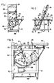
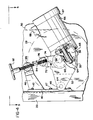
- the drive and tensioning means of the present invention is intended for utilization in a band saw and particularly in a meat cutting band saw of the type illustrated in Figs. 1 and 2.
- a band saw generally comprises a base frame 10 which supports a stationary table 12 on brackets 14, and a carriage 16 with a backing plate 17 is mounted on a runway 18 which captures a plurality of rollers 20 to which the carriage 16 is secured.
- the tops of the table and carriage are in the same plane, and a gage plate 21 is movably supported extending upward from table 12 to permit adjustment of the thickness of material to be cut.
- This construction permits the carriage 16 to be reciprocated laterally adjacent the stationary table 12 in order to feed the material through the saw and cut it to the desired width.
- a support column 22 which forms part of the frame structure of the band saw and to which is secured an upper housing 24.
- an upper band wheel 26 is journalled for rotation about its central axis in housing 24.
- Support column 22 preferably is secured to base frame 10 so as to be at an acute angle to the infeed direction of the material to be cut, as illustrated in Fig. 2, although the positioning of the support column may be vertical as is more conventional.
- Support column 22 extends into the lower portion of base frame 10 and supports the lower band wheel 28 through the tensioning and adjustment mechanism of the present invention, as described in more detail below.
- Encircling the upper and lower band wheels 26 and 28 is a band saw blade 30 which has one straight cutting flight extending through the stationary table 12 for cutting the material, and a return flight which extends along support column 22.
- An upper blade guide 32 is adjustably secured to a rod 34 supported by upper housing 24, to permit the blade guide 32 to be positioned toward and away from the cutting table to locate the blade guide 32 immediately above the upper surface of the material, while different thicknesses of material are cut.
- An upper blade guard 36 which has its lower end portion secured to blade guide 32, extends over the portion of the saw blade 30 between upper housing 24 and blade guide 32 to shield the blade along that portion of the flight above the blade guide.
- a lower blade guide (not shown) is also provided, being mounted to the base frame 10 of the band saw at a position aligned with the cutting flight of the band saw blade 30 and located below the table 12 and above the lower band wheel 28.
- a scrap catcher 38 is provided beneath table 12 and is suitably hinged at its lower end to move outward and downward from the closed position, as seen in Fig. 2.
- the catcher 38 encloses the lower band wheel 28, but can be opened for access to the lower band wheel 28, for cleaning, and for removing scraps from the catcher 38.
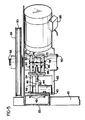
- a bracket 40 is secured by bolts 42 to the lower portion of support column 22, and has a cylindrical extension 44 formed in the lower portion thereof and a Y-shaped arm or yoke 46 formed at the upper portion thereof.
- Extension 44 has a cylindrical opening defined therein, which has its central axis parallel to the axis of rotation of lower band wheel 28.
- a pivot locating pin 48 is fixed in the opening, with the ends of the pin protruding.
- a support housing 50 is held by the ends of locating pin 48 which extend through arm extensions 52 and 54 formed on support housing 50, so that housing 50 is pivotally mounted to bracket 40.
- a gear box 56 is incorporated within support housing 50, in the region where the drive shaft 58 supporting lower band wheel 28 is journalled.
- Drive shaft 58 extends through housing 50, and is journalled on each side of the housing.
- a worm wheel 60 is keyed to the shaft, and is engaged by a worm gear 62, which is in turn keyed to an output shaft 64 of drive motor 66.
- the drive motor is mounted to a flange formed on the support housing 50 at one side of gear box 56.
- the motor is preferably mounted with output shaft 64 in a plane perpendicular to drive shaft 58 and on the opposite side thereof from pivot locating pin 48 in order to add the maximum amount of leverage from the weight of the motor to application of tension to the saw blade 30.
- support housing 50, gear box 56 and motor 66 all have exterior surfaces which merge to prevent scrap material from entering any of these components and thus prevent contamination thereof in areas which would otherwise be difficult to clean.
- the entire drive assembly is totally enclosed except for air passages 65 and 67 for cooling the motor, and its outer surfaces are easily cleaned.
- Electrical inputs to the motor are contained within the box 68 and, as shown in Figs. 1 and 2, extend from an electrical connector box 70 which is in turn connected to a power supply source.
- a further pair of extensions 72 and 74 are formed in the upper portion of housing 50. Between them is a cylindrical member 76 supported by screws 78 and 80 which are free to rotate in extensions 72 and 74, and are threaded into member 76 along its central axis, to permit pivotal movement of the member 76 about its central axis.
- Member 76 is provided with a diametrically extending threaded opening 82 perpendicular to its rotational axis.
- a threaded rod 84 is engaged within opening 82, and has its opposite end, which is oppositely threaded as shown in Fig. 4, received in a cylindrical member 86 which is identical to cylindrical member 76, except for the direction of threading.
- Cylindrical member 86 is in turn supported in the opening of Y-shaped arm 46, as shown in Fig. 5, by bolts 88 and 90 which are free to rotate within the arm 46 and are threaded into member 86 along its axis of rotation to permit pivotal movement thereof.
- handle92 Secured to the upper end portion of rod 84 is handle92which permits the operator of the sawto adjust tension in the blade 30 upon rotation of the handle 92.
- the operator need merely rotate the handle 92. This will cause the threaded engagement between the rod 84 and cylindrical members 76 and 86 to produce an expansion or contraction of the distance between these two members, and resulting pivotal rotation of the housing 50 about the axis of pin 48 will raise or lower the lower band wheel to increase or decrease the tension on the blade 30, as desired. This adjustment has no effect on the direct drive coupling of the motor to wheel 28.
- the motor 66 Since the motor 66 is secured to the support housing 50 on the opposite side of the axis of rotation of band wheel 28 from the pin 48, and the motor shaft is perpendicular to shaft 58, the weight of the motor will assist to the maximum extent in increasing the tension on the band saw blade due to the leverage resulting from its location at a maximum distance from the pin 48. Thus, less torque need be applied by the operator to handle 92 in order to increase the tension on the blade 30.
Landscapes
- Engineering & Computer Science (AREA)
- Mechanical Engineering (AREA)
- Sawing (AREA)
Claims (7)
Priority Applications (2)
| Application Number | Priority Date | Filing Date | Title |
|---|---|---|---|
| EP19820301586 EP0090102B1 (de) | 1982-03-25 | 1982-03-25 | Spanneinstellung für eine Bandsäge |
| DE8282301586T DE3277802D1 (en) | 1982-03-25 | 1982-03-25 | Tension adjustment for a band saw |
Applications Claiming Priority (1)
| Application Number | Priority Date | Filing Date | Title |
|---|---|---|---|
| EP19820301586 EP0090102B1 (de) | 1982-03-25 | 1982-03-25 | Spanneinstellung für eine Bandsäge |
Publications (3)
| Publication Number | Publication Date |
|---|---|
| EP0090102A2 EP0090102A2 (de) | 1983-10-05 |
| EP0090102A3 EP0090102A3 (en) | 1983-11-16 |
| EP0090102B1 true EP0090102B1 (de) | 1987-12-09 |
Family
ID=8189619
Family Applications (1)
| Application Number | Title | Priority Date | Filing Date |
|---|---|---|---|
| EP19820301586 Expired EP0090102B1 (de) | 1982-03-25 | 1982-03-25 | Spanneinstellung für eine Bandsäge |
Country Status (2)
| Country | Link |
|---|---|
| EP (1) | EP0090102B1 (de) |
| DE (1) | DE3277802D1 (de) |
Families Citing this family (2)
| Publication number | Priority date | Publication date | Assignee | Title |
|---|---|---|---|---|
| DE3700253A1 (de) * | 1987-01-07 | 1988-07-21 | Freund Reinhard Maschbau | Bandsaege zum zerteilen von tierkoerpern |
| JP7034850B2 (ja) * | 2018-06-28 | 2022-03-14 | 株式会社マキタ | 携帯用バンドソー |
Family Cites Families (6)
| Publication number | Priority date | Publication date | Assignee | Title |
|---|---|---|---|---|
| US1643829A (en) * | 1924-07-08 | 1927-09-27 | Biro Carl | Meat cutter |
| CH163071A (de) * | 1932-02-17 | 1933-07-31 | Pfeiffer Hugo | Bandsägemaschine. |
| US2492824A (en) * | 1945-01-05 | 1949-12-27 | Us Slicing Machine Co Inc | Meat and bone saw |
| US2617451A (en) * | 1947-08-23 | 1952-11-11 | Toledo Scale Co | Blade tensioning means for meat-cutting band saws |
| GB659930A (en) * | 1949-04-05 | 1951-10-31 | Thomas Robinson & Son Ltd | Improvements in and relating to band saws for woodworking and like machines |
| FR2439070A1 (fr) * | 1978-10-17 | 1980-05-16 | Gertwiller Const Mec Metalliqu | Perfectionnements aux scies a ruban |
-
1982
- 1982-03-25 EP EP19820301586 patent/EP0090102B1/de not_active Expired
- 1982-03-25 DE DE8282301586T patent/DE3277802D1/de not_active Expired
Also Published As
| Publication number | Publication date |
|---|---|
| EP0090102A2 (de) | 1983-10-05 |
| EP0090102A3 (en) | 1983-11-16 |
| DE3277802D1 (en) | 1988-01-21 |
Similar Documents
| Publication | Publication Date | Title |
|---|---|---|
| EP0715918B1 (de) | Doppelgehrungstischsäge | |
| US5040444A (en) | Saw blade position setting apparatus | |
| US4321849A (en) | Tension adjustment for a band saw | |
| AU3040095A (en) | Method and apparatus for cutting of elastomeric materials | |
| US20080271327A1 (en) | Powered Saw | |
| US5724740A (en) | Twin blade saw | |
| AU2004267934B2 (en) | Device for cutting and stripping meat | |
| EP0090102B1 (de) | Spanneinstellung für eine Bandsäge | |
| US4354410A (en) | Straight line insulation cutter assembly | |
| US3702604A (en) | Work mounting mechanism in slicing machine | |
| ATE212581T1 (de) | Schneidvorrichtung für lebensmittelprodukte | |
| US4346536A (en) | Tilting arbor belt sander | |
| CA1075005A (en) | Machine for cutting the lead ends of components mounted at printed-wiring boards | |
| US4154144A (en) | Milling machine power feed | |
| WO1998016356A1 (de) | Fleischschneidevorrichtung | |
| US4986155A (en) | Cutting apparatus for extruded materials | |
| US4055102A (en) | Band and saber saw arrangement | |
| JP4454719B2 (ja) | 食肉スライサー | |
| GB2061780A (en) | Involute knife sharpener | |
| AU680333B2 (en) | Twin blade saw | |
| CN218018748U (zh) | 一种农产品加工用切片装置 | |
| US4488381A (en) | Cutter apparatus | |
| CN219191444U (zh) | 一种可调节切割间距的纸箱加工用切割机 | |
| US4524663A (en) | Power hacksaw | |
| GB2091144A (en) | A blade grinder |
Legal Events
| Date | Code | Title | Description |
|---|---|---|---|
| PUAI | Public reference made under article 153(3) epc to a published international application that has entered the european phase |
Free format text: ORIGINAL CODE: 0009012 |
|
| PUAL | Search report despatched |
Free format text: ORIGINAL CODE: 0009013 |
|
| AK | Designated contracting states |
Designated state(s): DE FR GB |
|
| AK | Designated contracting states |
Designated state(s): DE FR GB |
|
| 17P | Request for examination filed |
Effective date: 19840508 |
|
| RAP1 | Party data changed (applicant data changed or rights of an application transferred) |
Owner name: HOBART CORPORATION (A CORPORATION OF THE STATE OF |
|
| RAP1 | Party data changed (applicant data changed or rights of an application transferred) |
Owner name: HOBART CORPORATION (A CORPORATION OF DELAWARE) |
|
| GRAA | (expected) grant |
Free format text: ORIGINAL CODE: 0009210 |
|
| AK | Designated contracting states |
Kind code of ref document: B1 Designated state(s): DE FR GB |
|
| PG25 | Lapsed in a contracting state [announced via postgrant information from national office to epo] |
Ref country code: FR Free format text: THE PATENT HAS BEEN ANNULLED BY A DECISION OF A NATIONAL AUTHORITY Effective date: 19871209 |
|
| REF | Corresponds to: |
Ref document number: 3277802 Country of ref document: DE Date of ref document: 19880121 |
|
| EN | Fr: translation not filed | ||
| PLBE | No opposition filed within time limit |
Free format text: ORIGINAL CODE: 0009261 |
|
| STAA | Information on the status of an ep patent application or granted ep patent |
Free format text: STATUS: NO OPPOSITION FILED WITHIN TIME LIMIT |
|
| PG25 | Lapsed in a contracting state [announced via postgrant information from national office to epo] |
Ref country code: GB Free format text: LAPSE BECAUSE OF NON-PAYMENT OF DUE FEES Effective date: 19881122 |
|
| 26N | No opposition filed | ||
| GBPC | Gb: european patent ceased through non-payment of renewal fee | ||
| PG25 | Lapsed in a contracting state [announced via postgrant information from national office to epo] |
Ref country code: DE Effective date: 19881201 |