EP0089838B1 - Mikrowellenofen mit einer Überwachungsschaltung - Google Patents
Mikrowellenofen mit einer Überwachungsschaltung Download PDFInfo
- Publication number
- EP0089838B1 EP0089838B1 EP83301543A EP83301543A EP0089838B1 EP 0089838 B1 EP0089838 B1 EP 0089838B1 EP 83301543 A EP83301543 A EP 83301543A EP 83301543 A EP83301543 A EP 83301543A EP 0089838 B1 EP0089838 B1 EP 0089838B1
- Authority
- EP
- European Patent Office
- Prior art keywords
- monitor
- circuit
- power
- switch
- fuse
- Prior art date
- Legal status (The legal status is an assumption and is not a legal conclusion. Google has not performed a legal analysis and makes no representation as to the accuracy of the status listed.)
- Expired
Links
Images

Classifications
-
- H—ELECTRICITY
- H05—ELECTRIC TECHNIQUES NOT OTHERWISE PROVIDED FOR
- H05B—ELECTRIC HEATING; ELECTRIC LIGHT SOURCES NOT OTHERWISE PROVIDED FOR; CIRCUIT ARRANGEMENTS FOR ELECTRIC LIGHT SOURCES, IN GENERAL
- H05B6/00—Heating by electric, magnetic or electromagnetic fields
- H05B6/64—Heating using microwaves
- H05B6/66—Circuits
- H05B6/666—Safety circuits
Definitions
- the present invention relates to a microwave oven having a monitor circuit.
- Such a monitor circuit is needed in a microwave oven to prevent microwaves from accidentally being scattered from the cavity of the microwave oven. This could otherwise occur when an interlock door switch becomes faulty.
- Different countries all around the world impose safety standards which require microwave ovens to be provided with such monitor circuits.
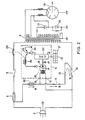
- Fig. 1 shows a known monitor circuit for a microwave oven.
- the circuit comprises a commercial power source 1, a house main power fuse 2, an AC plug 3, and a microwave oven main fuse 4 rated at about 6-16 A.
- a first interlock switch 5, which is closed when a latch door is closed, is connected in series with the main fuse 4 and with a primary winding of a high voltage transformer 9 via relay terminals 8 of a relay 7 included within a touch control circuit 6.
- a second interlock switch 10 is connected between the primary winding of the transformer 9 and the AC plug 3.
- the first and the second interlock switches 5 and 10 are connected in series with the primary winding of the transformer 9.
- a monitor switch 11 is connected in series with a monitor resistor 12. This switch 11 is mechanically opened when the latch door is closed, and closed when the door is opened.
- the terminal of the monitor switch 11 remote from the monitor resistor 12 is connected to a point between the main fuse 4 and the first interlock switch 5.
- the monitor resistor 12 is connected to the primary winding of the transformer 9.
- Two terminals 13 and 14 are provided as power input terminals for the touch control circuit 6 which is electronically operated.
- the terminal 13 is connected to the AC plug 3 via the main fuse 4, and the terminal 14 is directly connected to the AC plug 3.
- Power is supplied to the touch control circuit 6 by way of a power transformer 15.
- a rectifier 16 is connected for converting AC power to DC power.
- the touch control circuit 6 uses DC power from the rectifier 16 for controlling the microwave oven.
- a conventional microwave generating circuit including a high voltage condenser 17, a high voltage diode 18, a magnetron 19 and the like are connected to the secondary winding of the transformer 9.
- the monitor resistor 12 is needed.
- the value of the microwave oven main fuse 4 is not fixed, but rather is variable from one country to another and may be rated at anything from 6-16 A. Depending upon this fuse rating, it may happen that the monitor current can reach such a magnitude that the house main fuse 2 is not adequately protected by the fuse 4 so that it may blow despite the provision of the monitor resistor 12. This is contrary to normal safety standards, which demand that the house main fuse 2 should not be blown when the monitor circuit is operated.
- said self-holding relay is maintained energized by a current which no longer flows through said monitor circuit.
- United States patent specification US-A-4054769 discloses a short-circuiting monitor circuit for a microwave oven.
- a heat-responsive electrical resistance element is connected in the monitor circuit and normally holds closed mechanically an additional protector switch which is in series with the main door switch. In the event of failure of the main door switch, the short circuiting current which flows in the monitor circuit causes the resistance element to fail, and the protector switch opens.
- a microwave oven having a door interlock switch connected in series with a power utilization circuit of the oven, said interlock switch being arranged to be opened upon opening of a door of the oven; a monitor circuit connected in parallel with said power utilization circuit and including a monitor switch which is arranged to be closed upon opening of a door of the oven; and a power control circuit which is connected to a point on the monitor circuit so that said power control circuit is powered continuously by current which flows in a part of the monitor circuit, said power control circuit being responsive to the cutting of the power supplied thereto by way of said part of the monitor circuit to disable the power utilization circuit; said monitor circuit being connected across power supply terminals coupled to said power utilisation circuit so that if the interlock switch fails to open when the oven door opens, causing power to be applied to said terminals while said-monitor switch is closed, the current flowing through the monitor circuit causes a monitor fuse which is connected in said part of the monitor circuit, to blow, thereby to cut the power supply to said power control circuit and thereby disable the
- a microwave oven having a door interlock switch connected in series with a power utilization circuit of the oven, said interlock switch being arranged to be opened upon opening of a door of the oven; a monitor circuit connected in parallel with said power utilization circuit, and including a monitor switch which is arranged to be closed upon opening of the door of the oven and a current-limiting resistor in series with said monitor switch; and a power control circuit which includes a touch key panel and a power transformer the primary winding of which is connected to a point on the monitor circuit so that the power control circuit is continuously powered by current which flows through said primary winding and through a part of said monitor circuit, which part excludes the monitor switch and the current-limiting resistor, said control circuit being responsive to the cutting of power supply thereto to open the contact of a power switch connected in series with the power utilization circuit; said monotor circuit being connected across power supply terminals coupled to said power utilization circuit so that if the interlock switch fails to open when the oven door opens, causing power to be applied to said terminal
- a monitor fuse 20 is connected to a power side terminal of the microwave oven main fuse 4 and the monitor switch 11.
- the current capacity of thus fuse 20 is about 0.5-1 A which is much less than that of the main fuse 4 of about 6-16 A.
- a connection point between the monitor fuse 20 and the monitor switch 11 is connected to the input terminal 13 of a power input circuit such as the power transformer 15 in the touch control circuit 6.
- the monitor switch 11 is connected to the AC plug 3 having three terminals via the monitor resistor 12 and the second interlock switch 10.
- a touch key panel 21 is provided for key operations for the touch control circuit 6.
- a .CPU 22 is provided within the touch control circuit 6 for controlling the operations of the microwave oven.
- An NPN transistor 23 is connected to the CPU 22 via a drive circuit 24.
- a cook start relay 25 is connected at the collector side of this transistor 23.
- Relay terminals 26 are related to the cook start relay 25.
- the relay terminals 26 are connected to the primary winding of the high voltage transformer 9 and to the first interlock switch 5 coupled to the microwave oven main fuse 4.
- the monitor switch 11 is mechanically opened when the latch door is closed, and mechanically closed when this door is opened.
- the first and the second interlock switches 5 and 10 are mechanically closed when the latch door is closed, and mechanically opened when this door is opened.
- the interlock switches 5 and 10 function to allow the power supply to the - remaining portions of this circuit only when the latch door is tightly closed.
- a foodstuff is disposed within the microwave oven and the latch door is closed. Responsive to this operation, the monitor switch 11 is opened, and the first and the second interlock switches 5 and 10 are closed, respectively.
- a cooking start key 21 in the touch key panel 21 is operated to input a cooking start signal into the CPU 22.
- the cooking start signal is inputted into the CPU 22 and outputted into the NPN transistor 23 via the drive circuit 24.
- the NPN transistor 23 is made conductive to supply power energy to the cooking start relay 25, so that the cooking start relay terminals 26 are closed.
- the commercial power is supplied from the AC plug 3 into the high voltage transformer 9 through the main fuse 4, the first interlock switch 5, the cooking start relay terminals 26, and the second interlock switch 10.
- the magnetron 19 is energized with a high voltage to generate microwave. Through the monitor fuse 20, the commercial power is supplied to the power transformer 15 in the touch control circuit 6 to operate the CPU 22.
- the second interlock switch 10 fails so that it cannot open.
- the monitor switch 11 is closed, so that the power energy is momentarily supplied from the AC plug 3 into the monitor fuse 20, the monitor switch 11, the monitor resistor 12, and the second interlock switch 10 as indicated with an arrow B.
- the monitor fuse 20 is blown.
- the input terminal 13 of the power transformer 15 in the touch control circuit 6 is made open so that the touch control circuit 6 no longer receives power.
- the cooking start relay 25 also becomes deenergized, so that the cooking start relay terminals 26 are opened.
- the primary winding of the high voltage transformer 9 is thereby isolated from the power source, and the magnetron can no longer generate microwaves. Therefore, the microwave leakage from the oven cavity can be prevented.
- the monitor fuse 20 is permitted to blow when the second interlock switch 10 cannot be opened due to damage.
- the power supply to the touch control circuit 6 can be cut to stop energization of the magnetron 19.
- the oven main fuse 4 is not cut.
- a line leading to the monitor fuse 20, the monitor switch 11, and the monitor resistor 12 is connected to the power source side of the main fuse 4.
- this line leading to the monitor fuse 20 is connected to the point between the main fuse 4 and the first interlock switch 5, namely, to the side including the high voltage transformer 9.
- the monitor fuse 20 can blow to permit the cooking start relay terminals 26 to open.
- the monitor fuse 20 also serves as a fuse for protecting against short- circuiting in the secondary circuit of the cooking control circuit 6. Since the touch control circuit 6 consumes an approximately-constant current, the resistance of the monitor resistor 12 for limiting a current can be freely selected.
- the first interlock switch 5 is not damaged, so that it operates successfully without any problem of failure. If necessary, an additional monitor circuit can be provided for protecting the first interlock switch 5.
Claims (6)
Applications Claiming Priority (2)
| Application Number | Priority Date | Filing Date | Title |
|---|---|---|---|
| JP4021282U JPS58142892U (ja) | 1982-03-19 | 1982-03-19 | 電子レンジのモニタ−回路 |
| JP40212/82U | 1982-03-19 |
Publications (2)
| Publication Number | Publication Date |
|---|---|
| EP0089838A1 EP0089838A1 (de) | 1983-09-28 |
| EP0089838B1 true EP0089838B1 (de) | 1989-02-01 |
Family
ID=12574463
Family Applications (1)
| Application Number | Title | Priority Date | Filing Date |
|---|---|---|---|
| EP83301543A Expired EP0089838B1 (de) | 1982-03-19 | 1983-03-18 | Mikrowellenofen mit einer Überwachungsschaltung |
Country Status (4)
| Country | Link |
|---|---|
| EP (1) | EP0089838B1 (de) |
| JP (1) | JPS58142892U (de) |
| AU (1) | AU557262B2 (de) |
| DE (1) | DE3379147D1 (de) |
Cited By (1)
| Publication number | Priority date | Publication date | Assignee | Title |
|---|---|---|---|---|
| CN103175237A (zh) * | 2013-03-27 | 2013-06-26 | 福州高奇智芯电源科技有限公司 | 微波炉及其自适应功率输出控制方法 |
Families Citing this family (1)
| Publication number | Priority date | Publication date | Assignee | Title |
|---|---|---|---|---|
| JP3288234B2 (ja) * | 1996-11-29 | 2002-06-04 | 株式会社東芝 | 加熱調理器 |
Citations (1)
| Publication number | Priority date | Publication date | Assignee | Title |
|---|---|---|---|---|
| US4054769A (en) * | 1976-03-04 | 1977-10-18 | The Tappan Company | Microwave oven interlock switch safety |
Family Cites Families (2)
| Publication number | Priority date | Publication date | Assignee | Title |
|---|---|---|---|---|
| USRE30248E (en) * | 1974-08-03 | 1980-04-01 | Amana Refrigeration, Inc. | Safety interlock system for microwave ovens |
| JPS57154789A (en) * | 1981-03-20 | 1982-09-24 | Matsushita Electric Ind Co Ltd | High frequency heater |
-
1982
- 1982-03-19 JP JP4021282U patent/JPS58142892U/ja active Pending
-
1983
- 1983-03-17 AU AU12550/83A patent/AU557262B2/en not_active Ceased
- 1983-03-18 EP EP83301543A patent/EP0089838B1/de not_active Expired
- 1983-03-18 DE DE8383301543T patent/DE3379147D1/de not_active Expired
Patent Citations (1)
| Publication number | Priority date | Publication date | Assignee | Title |
|---|---|---|---|---|
| US4054769A (en) * | 1976-03-04 | 1977-10-18 | The Tappan Company | Microwave oven interlock switch safety |
Cited By (2)
| Publication number | Priority date | Publication date | Assignee | Title |
|---|---|---|---|---|
| CN103175237A (zh) * | 2013-03-27 | 2013-06-26 | 福州高奇智芯电源科技有限公司 | 微波炉及其自适应功率输出控制方法 |
| CN103175237B (zh) * | 2013-03-27 | 2015-07-15 | 福州高奇智芯电源科技有限公司 | 微波炉及其自适应功率输出控制方法 |
Also Published As
| Publication number | Publication date |
|---|---|
| JPS58142892U (ja) | 1983-09-26 |
| AU557262B2 (en) | 1986-12-18 |
| EP0089838A1 (de) | 1983-09-28 |
| AU1255083A (en) | 1983-09-22 |
| DE3379147D1 (en) | 1989-03-09 |
Similar Documents
| Publication | Publication Date | Title |
|---|---|---|
| EP1919260B1 (de) | Elektrisches gerät und heiz-kochgerät | |
| US3699300A (en) | System for detecting safety switch failure | |
| JPH0224089B2 (de) | ||
| US3816688A (en) | Safety interlock system for microwave ovens | |
| EP0074408B1 (de) | Vorrichtung für aufheizen mit hochfrequenz | |
| US4096370A (en) | Microwave oven door interlock switch system | |
| WO1994019854A1 (en) | Electrical supply safety plug | |
| EP0089838B1 (de) | Mikrowellenofen mit einer Überwachungsschaltung | |
| US3872320A (en) | Furnace control circuit | |
| US6399931B1 (en) | Microwave oven with door safety switch device | |
| US3746938A (en) | Interlock circuit | |
| KR940007475B1 (ko) | 전자레인지의 전원회로 | |
| CN106655898A (zh) | 一种电抗器柜控制电路 | |
| USRE30248E (en) | Safety interlock system for microwave ovens | |
| USRE28822E (en) | Safety interlock system for microwave ovens | |
| EP0981265B1 (de) | Mikrowellenherd versehen mit eine Sicherungseinrichtung für den Hochspannungstransformator | |
| WO2004032168A1 (en) | Electrical switching method and apparatus | |
| KR200153223Y1 (ko) | 전자렌지에서의 과부하 방지회로 | |
| KR100218962B1 (ko) | 전자렌지의 메인회로 | |
| US2741527A (en) | Overload relay circuit | |
| CN117440551A (zh) | 一种微波炉的门检测电路及检测判定方法、微波炉 | |
| KR900003461Y1 (ko) | 3상 전동기의 무접점 스위치 동작을 겸한 절전 및 안전장치 | |
| KR100313047B1 (ko) | 전자렌지의돌입전류감쇠회로 | |
| JPS5840793A (ja) | 高周波加熱装置用電源回路 | |
| KR850002655Y1 (ko) | 전자레인지의 오동작 방지회로 |
Legal Events
| Date | Code | Title | Description |
|---|---|---|---|
| PUAI | Public reference made under article 153(3) epc to a published international application that has entered the european phase |
Free format text: ORIGINAL CODE: 0009012 |
|
| AK | Designated contracting states |
Designated state(s): BE CH DE GB LI SE |
|
| 17P | Request for examination filed |
Effective date: 19840328 |
|
| 17Q | First examination report despatched |
Effective date: 19860327 |
|
| R17C | First examination report despatched (corrected) |
Effective date: 19870429 |
|
| GRAA | (expected) grant |
Free format text: ORIGINAL CODE: 0009210 |
|
| AK | Designated contracting states |
Kind code of ref document: B1 Designated state(s): BE CH DE GB LI SE |
|
| REF | Corresponds to: |
Ref document number: 3379147 Country of ref document: DE Date of ref document: 19890309 |
|
| PLBE | No opposition filed within time limit |
Free format text: ORIGINAL CODE: 0009261 |
|
| STAA | Information on the status of an ep patent application or granted ep patent |
Free format text: STATUS: NO OPPOSITION FILED WITHIN TIME LIMIT |
|
| 26N | No opposition filed | ||
| EAL | Se: european patent in force in sweden |
Ref document number: 83301543.1 |
|
| PGFP | Annual fee paid to national office [announced via postgrant information from national office to epo] |
Ref country code: GB Payment date: 19980309 Year of fee payment: 16 |
|
| PGFP | Annual fee paid to national office [announced via postgrant information from national office to epo] |
Ref country code: SE Payment date: 19980317 Year of fee payment: 16 |
|
| PGFP | Annual fee paid to national office [announced via postgrant information from national office to epo] |
Ref country code: DE Payment date: 19980327 Year of fee payment: 16 |
|
| PGFP | Annual fee paid to national office [announced via postgrant information from national office to epo] |
Ref country code: CH Payment date: 19980408 Year of fee payment: 16 |
|
| PGFP | Annual fee paid to national office [announced via postgrant information from national office to epo] |
Ref country code: BE Payment date: 19980518 Year of fee payment: 16 |
|
| PG25 | Lapsed in a contracting state [announced via postgrant information from national office to epo] |
Ref country code: GB Free format text: LAPSE BECAUSE OF NON-PAYMENT OF DUE FEES Effective date: 19990318 |
|
| PG25 | Lapsed in a contracting state [announced via postgrant information from national office to epo] |
Ref country code: SE Free format text: LAPSE BECAUSE OF NON-PAYMENT OF DUE FEES Effective date: 19990319 |
|
| PG25 | Lapsed in a contracting state [announced via postgrant information from national office to epo] |
Ref country code: LI Free format text: LAPSE BECAUSE OF NON-PAYMENT OF DUE FEES Effective date: 19990331 Ref country code: CH Free format text: LAPSE BECAUSE OF NON-PAYMENT OF DUE FEES Effective date: 19990331 Ref country code: BE Free format text: LAPSE BECAUSE OF NON-PAYMENT OF DUE FEES Effective date: 19990331 |
|
| BERE | Be: lapsed |
Owner name: SHARP K.K. Effective date: 19990331 |
|
| EUG | Se: european patent has lapsed |
Ref document number: 83301543.1 |
|
| GBPC | Gb: european patent ceased through non-payment of renewal fee |
Effective date: 19990318 |
|
| REG | Reference to a national code |
Ref country code: CH Ref legal event code: PL |
|
| EUG | Se: european patent has lapsed |
Ref document number: 83301543.1 |
|
| PG25 | Lapsed in a contracting state [announced via postgrant information from national office to epo] |
Ref country code: DE Free format text: LAPSE BECAUSE OF NON-PAYMENT OF DUE FEES Effective date: 20000101 |