EP0089092B1 - Stationary beer container - Google Patents
Stationary beer container Download PDFInfo
- Publication number
- EP0089092B1 EP0089092B1 EP83200352A EP83200352A EP0089092B1 EP 0089092 B1 EP0089092 B1 EP 0089092B1 EP 83200352 A EP83200352 A EP 83200352A EP 83200352 A EP83200352 A EP 83200352A EP 0089092 B1 EP0089092 B1 EP 0089092B1
- Authority
- EP
- European Patent Office
- Prior art keywords
- container
- beer
- tube
- housing part
- line
- Prior art date
- Legal status (The legal status is an assumption and is not a legal conclusion. Google has not performed a legal analysis and makes no representation as to the accuracy of the status listed.)
- Expired
Links
- 235000013405 beer Nutrition 0.000 title claims abstract description 57
- 238000007789 sealing Methods 0.000 claims description 12
- 230000008878 coupling Effects 0.000 claims description 6
- 238000010168 coupling process Methods 0.000 claims description 6
- 238000005859 coupling reaction Methods 0.000 claims description 6
- 238000007599 discharging Methods 0.000 claims description 2
- 239000012780 transparent material Substances 0.000 claims description 2
- 238000004140 cleaning Methods 0.000 abstract description 10
- 238000010079 rubber tapping Methods 0.000 abstract 2
- CURLTUGMZLYLDI-UHFFFAOYSA-N Carbon dioxide Chemical compound O=C=O CURLTUGMZLYLDI-UHFFFAOYSA-N 0.000 description 15
- 239000007789 gas Substances 0.000 description 6
- 239000007788 liquid Substances 0.000 description 3
- 238000005476 soldering Methods 0.000 description 2
- 239000012530 fluid Substances 0.000 description 1
- 238000012423 maintenance Methods 0.000 description 1
- 239000008237 rinsing water Substances 0.000 description 1
- XLYOFNOQVPJJNP-UHFFFAOYSA-N water Substances O XLYOFNOQVPJJNP-UHFFFAOYSA-N 0.000 description 1
- 238000003466 welding Methods 0.000 description 1
Images


Classifications
-
- B—PERFORMING OPERATIONS; TRANSPORTING
- B67—OPENING, CLOSING OR CLEANING BOTTLES, JARS OR SIMILAR CONTAINERS; LIQUID HANDLING
- B67D—DISPENSING, DELIVERING OR TRANSFERRING LIQUIDS, NOT OTHERWISE PROVIDED FOR
- B67D1/00—Apparatus or devices for dispensing beverages on draught
- B67D1/08—Details
- B67D1/0829—Keg connection means
- B67D1/0831—Keg connection means combined with valves
- B67D1/0832—Keg connection means combined with valves with two valves disposed concentrically
-
- B—PERFORMING OPERATIONS; TRANSPORTING
- B67—OPENING, CLOSING OR CLEANING BOTTLES, JARS OR SIMILAR CONTAINERS; LIQUID HANDLING
- B67D—DISPENSING, DELIVERING OR TRANSFERRING LIQUIDS, NOT OTHERWISE PROVIDED FOR
- B67D1/00—Apparatus or devices for dispensing beverages on draught
- B67D1/08—Details
- B67D1/0801—Details of beverage containers, e.g. casks, kegs
Definitions
- the invention is related to a stationary beer container with openings at the lower and upper side of the container for discharging beer and supplying pressurized gas respectively, whereby the lower opening is provided with connection means.
- a beer container is known from US-A-3,221,931.
- a stationary container with a contents of for instance 1000 I is advantageous above the use of kegs with a contents of for instance 50 I.
- Drawing beer from a keg is normally much more simple than the switching from an empty stationary container, because of the fact that in the beer keg a tap rod is present, that is connected into the bung hole of the keg.
- This tap rod comprises a vertical tube of which the open lower end extends up to the bottom of the keg. The upper end is closed by an end wall. Below the end wall windows are present that debouche in a space around the upper end of the tube. Around this part of the tube a funnel-shaped housing is present.
- the space between the tube in the housing is outwardly closed by a rubber sleeve around the tube, that is pressed outwardly by spring means, so that the opening and also the interior of the keg is closed with regard to the surroundings, see for instance NL-A-78.06761.
- the beer line is provided with a tap head, that also is provided with a connection to a carbondioxid cylinder or other gas under pressure.
- the invention aims to provide a stationary beer container with means, that anyhow partly correspond with the known tap rod, so the inn keeper is able to use the same tap head which is known to him also for a stationary container.
- the tank car that is destined to fill the stationary tank also may comprise such a connecting head as well as the cleaning device destined to clean the container from time to time.
- connection means comprises a housing part and a body fitting therein and connected therewith, said housing part being shaped as a chamber, which is open at the side turned away from the lower opening of the container, which chamber is connected to a vertical line extending to the upper opening of the container and that the body comprises a tube closed at one end by a transverse wall, windows in the tube below the transverse wall, an elastic sealing sleeve around this end of the tube and a pressure spring to press the sealing sleeve into the closed position, whereby the body is arranged in such a way in the housing part, that the sealing sleeve in closed position closes the ring-shaped opening between tube and open side of the chamber of the housing part, and that the free end of the tube is connected to the lower opening of the container.
- An identical head can be used for cleaning and filling the beer container.
- the substantially vertically extending line between the housing part and the upper opening of the beer container comprises transparent material at least over a part of its length.
- the beer level in the beer container can be determined.
- the cleaning and/or rinsing fluid flows under pressure firstly through this line so that this is cleaned intensively.
- the beer container 1 for instance has the shape of an upright cylinder with a contents of for instance 1000 I, that with legs 2 is supported on the floor 3 of a storage room, for instance the cellar of a cafe or a restaurant.
- a line 4 connects to the lower end of the container 1 and a nozzle 5 is present on the upper side.
- This nozzle 5 is suited for supplying gas under pressure, preferably carbondioxid, and is also used for cleaning the container 1.
- connection means shown in detail in Figs. 4 and 5 is indicated with A and B.
- the house part A of the connection means comprises a cup-shaped chamber 6 with a central connection 7 a sideways connection 1 and a flange edge 9.
- the chamber 6 is connected to the container 1. On the central connection 7 said fixed line 4 is connected that also is shown in Fig. 1.
- a line 10 which at least partly is transparent is joined and which extends to said nozzle 5.
- body B In the housing part A body B is mounted, that corresponds greatly with the tap rod used for beer barrels.
- a tap rod is known for instance from NL-A-78.06761.
- a tap head C On the free end of this body B with a bayonet connection a tap head C fits that is also usable for beer kegs.
- the body B comprises a tube 11, however, shorter than usual, that at its first end is closed by a cross wall 12. Under the cross wall 12 usual windows 13 are present.
- an enlarged housing 14 is provided that is as usual provided with windows and has a flange edge 15, on which the connection of the tap head C fits.
- this housing 14 is fixed to the line 11 and serves as a seat for a pressure spring 16 that presses a rubber sealing sleeve 17 between the outer edge of the cross wall 12 of the tube 11 and the inner edge of the housing 14.
- the lower end of the tube 11 is provided with a fixed collar 18 with an 0-ring seal 19, which seals in the central connection 7 of the housing part A.
- a flange collar 20 is connected by soldering or the like. With the aid of this flange collar 20 and with not shown bolts the body B is arranged in the house part A with an O-ring seal 21.
- the tap head C is not yet provided.
- This tap head C comprises in a known way a flange part 22 that by rotation can be fixed to the flange edge 15, a tube 24 that can be moved outwardly with the aid of a lever 23, a sideways connection 25 for gas under pressure and a connection 126 to the not shown tap.
- the beer is pressed downwardly and rises through the line 4, the line 11, the windows 13 in the tap head C and from there through the connection 26 in the tap line 29 to the tap (not shown).
- the cleaning of the container can also be performed by the inn keeper with the aid of a head C to which he is accustomed.
- the tank car To fill the beer container from a movable tanker, such as a tank car, the tank car has the same head C, see Fig. 3, in which the tank car is indicated with 38.
- the head C of the tank car 38 is connected to this tank car 38 through a flexible hose 39, in which two hose wheels 40 and a pump 41 are present.
- a carbondioxid cylinder 42 through a line 43 is connected to the upper end of the tank car 38.
- the filling line 39 is connected to the head C at 26.
- the filling of the container 1 so takes place from below. As the level of the beer rises, more carbondioxid is blown away, so the overpressure is maintained.
- the head C used for drawing is fixed to the beer line 29 and the carbondioxid line 28.
- the filling head C forms a part of the tank car 38 and is fixed to the lines 39 and 44.
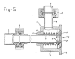
- connection means The second embodiment of the connection means is shown in Fig. 5.
- the house part A just as in the first embodiment comprises a chamber 6, a flange edge 9 and a sideways connection part 8, which maintenance reasons is coupled with a coupling D to the vertical line 10.
- the body B again comprises a tube 11, a closure wall 12, windows 13, a sealing sleeve 17 and a pressure spring 16.
- the widened housing 14 fails because this is not necessary for a beer container.
- the pressure spring 16 now abuts the bottom of the chamber 6.
- the tube 11 in a sealing manner is extended through a central passage 47 of the housing part A and is for instance by welding or soldering connected to that housing part A.
- the other end of the line 11 is connected through a coupling D to the fixed line 4 of the container 1.
- the second embodiment operates in exactly the same way as the first embodiment.
- the head C grips flange edge 9, which for that reason is designed corresponding to the flange edge 15 of the first embodiment.
Abstract
Description
- The invention is related to a stationary beer container with openings at the lower and upper side of the container for discharging beer and supplying pressurized gas respectively, whereby the lower opening is provided with connection means. Such a beer container is known from US-A-3,221,931.
- Mostly in the cellar of a cafe, restaurant or the like one or more of such containers is or are positioned which are filled by a tank car. In case a container is empty a new container has to be connected by disconnecting the coupling between the empty tank and the beer line extending to the cafe and to connect again said line to a full container. Moreover, the line between the carbondioxid cylinders or the like has to be disconnected from the empty container and has to be connected again to the full container. Moreover, the empty tank has to be cleaned from time to time with water and organic cleaning liquid for which reason also couplings are necessary to convey the cleaning liquid and the rinsing water to and from the container. This is rather complicated with the chance of errors. Moreover, connecting and disconnecting is rather time consuming.
- Yet a stationary container with a contents of for instance 1000 I is advantageous above the use of kegs with a contents of for instance 50 I.
- Drawing beer from a keg is normally much more simple than the switching from an empty stationary container, because of the fact that in the beer keg a tap rod is present, that is connected into the bung hole of the keg. This tap rod comprises a vertical tube of which the open lower end extends up to the bottom of the keg. The upper end is closed by an end wall. Below the end wall windows are present that debouche in a space around the upper end of the tube. Around this part of the tube a funnel-shaped housing is present. The space between the tube in the housing is outwardly closed by a rubber sleeve around the tube, that is pressed outwardly by spring means, so that the opening and also the interior of the keg is closed with regard to the surroundings, see for instance NL-A-78.06761.
- To connect the keg the beer line is provided with a tap head, that also is provided with a connection to a carbondioxid cylinder or other gas under pressure.
- After arranging the tap head on the tap rod and pressing downwardly a lever a connection is provided between the carbondioxid cylinder and the beer keg and between the beer keg and the tap which is present in the cafe. By pressing downwardly the lever the rubber sleeve is pressed downwardly around the tube against the action of the spring means, by which the windows in the tap rod come into connection with the beer line to the tap, see NL-A-78.06761. The inn keeper is accustomed to work with such a tap head, that ensures that no errors are made when kegs are used.
- The invention aims to provide a stationary beer container with means, that anyhow partly correspond with the known tap rod, so the inn keeper is able to use the same tap head which is known to him also for a stationary container. Moreover, the tank car that is destined to fill the stationary tank also may comprise such a connecting head as well as the cleaning device destined to clean the container from time to time.
- This aim according to the invention is obtained by the fact that said connection means comprises a housing part and a body fitting therein and connected therewith, said housing part being shaped as a chamber, which is open at the side turned away from the lower opening of the container, which chamber is connected to a vertical line extending to the upper opening of the container and that the body comprises a tube closed at one end by a transverse wall, windows in the tube below the transverse wall, an elastic sealing sleeve around this end of the tube and a pressure spring to press the sealing sleeve into the closed position, whereby the body is arranged in such a way in the housing part, that the sealing sleeve in closed position closes the ring-shaped opening between tube and open side of the chamber of the housing part, and that the free end of the tube is connected to the lower opening of the container.
- On this connection means a traditional tap head fits, with which beer from kegs is tapped whereby the inn keeper performs exactly the same manipulations as in case kegs are used.
- An identical head can be used for cleaning and filling the beer container.
- It is preferred that the substantially vertically extending line between the housing part and the upper opening of the beer container comprises transparent material at least over a part of its length.
- By this at all times the beer level in the beer container can be determined.
- During cleaning the beer container the cleaning and/or rinsing fluid flows under pressure firstly through this line so that this is cleaned intensively.
- The invention will be elucidated with the aid of the drawing in which:
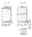
- Fig. 1 shows schematically a view of a full beer container in store;
- Fig. 2 shows the same beer container during drawing beer;
- Fig. 3 shows the same beer container during filling
- Fig. 4 shows a longitudinal section through the connecting device of the beer container according to the first embodiment with a known tap head on it; and
- Fig. 5 is a longitudinal section through the connecting means of the beer container according to a second embodiment.
- The
beer container 1 for instance has the shape of an upright cylinder with a contents of for instance 1000 I, that withlegs 2 is supported on thefloor 3 of a storage room, for instance the cellar of a cafe or a restaurant. - A
line 4 connects to the lower end of thecontainer 1 and anozzle 5 is present on the upper side. Thisnozzle 5 is suited for supplying gas under pressure, preferably carbondioxid, and is also used for cleaning thecontainer 1. - The connection means shown in detail in Figs. 4 and 5 is indicated with A and B.
- Firstly Fig. 4 will be discussed.
- The house part A of the connection means comprises a cup-
shaped chamber 6 with a central connection 7 asideways connection 1 and a flange edge 9. - The
chamber 6 is connected to thecontainer 1. On thecentral connection 7 saidfixed line 4 is connected that also is shown in Fig. 1. - At the sideways connection 8 a
line 10 which at least partly is transparent is joined and which extends to saidnozzle 5. - In the housing part A body B is mounted, that corresponds greatly with the tap rod used for beer barrels. Such a tap rod is known for instance from NL-A-78.06761. On the free end of this body B with a bayonet connection a tap head C fits that is also usable for beer kegs.
- As also is the case with the known tap rod the body B comprises a
tube 11, however, shorter than usual, that at its first end is closed by across wall 12. Under thecross wall 12usual windows 13 are present. - About the
tube 11 an enlarged housing 14 is provided that is as usual provided with windows and has aflange edge 15, on which the connection of the tap head C fits. - The small end of this housing 14 is fixed to the
line 11 and serves as a seat for apressure spring 16 that presses arubber sealing sleeve 17 between the outer edge of thecross wall 12 of thetube 11 and the inner edge of the housing 14. - The lower end of the
tube 11 is provided with afixed collar 18 with an 0-ring seal 19, which seals in thecentral connection 7 of the housing part A. - About the housing 14 a
flange collar 20 is connected by soldering or the like. With the aid of thisflange collar 20 and with not shown bolts the body B is arranged in the house part A with an O-ring seal 21. - In the
container 1 according to Fig. 1 the tap head C is not yet provided. - This tap head C comprises in a known way a
flange part 22 that by rotation can be fixed to theflange edge 15, atube 24 that can be moved outwardly with the aid of alever 23, asideways connection 25 for gas under pressure and a connection 126 to the not shown tap. - In the position according to Fig. 1 the tap head C is not mounted at the body B. The
spring 16 keeps therubber sleeve 17 in the position as shown in Fig. 4, by which thecontainer 1 is closed. The beer that enters thetube 11 through theline 4 comes through thewindows 13 and the windows in the housing 14 into thechamber 6 of the housing part A. From there the beer rises up to the connection 8 into thetransparent tube 10. Thistube 10 again is throughnozzle 5 in connection with the interior of thecontainer 3. Hence a communicating connection is formed by which the beer in thetube 10 is at the same height as in thecontainer 1. Above the liquid level in the container an amount of carbondioxid under pressure is present. - By this it is possible to determine the beer level in the
container 1. This also holds when the tap head C is indeed connected to the body B, but thelever 23 is still not pivoted in the clock-wise direction. This pivoting causes thetube 24 in the tap head C to move to the left, by which therubber sleeve 17 is pressed to the left until beyond the other side of thewindows 13. - This situation occurs during drawing beer, see Fig. 2. Here the
carbondioxid cylinders 27 are through aline 28 connected to theconnection 25 of the tap head C. On theconnection 26 of the tap head C a line is present to the not shown tap, that is present in the location where beer is drawn. Thisline 29 in general is cooled and may comprise a pump, not shown, in case this is necessary owing to the distance. The beer is under overpressure of the carbondioxid gas from thecylinders 27. - Thus, in case a
full container 1 according to Fig. 1 has to be put into use of the tap head C is connected to the body B. On this tap head C thecarbondioxid line 28 and thebeer line 29 are already mounted. After opening thecarbondioxid line 28 and pivoting thelever 23 the carbondioxid comes from thecylinders 27 into the body B and moves from theconnection 25 of the tap head C along the opened sealingsleeve 17, the housing 14, the windows in the house 14, thechamber 6 of the house part A, the connection 8, theriser line 10 and thenozzle 5 to thecontainer 1 above the beer. - The beer is pressed downwardly and rises through the
line 4, theline 11, thewindows 13 in the tap head C and from there through theconnection 26 in thetap line 29 to the tap (not shown). - To determine the level of the
container 1 it is sufficient to pivot thelever 23 to the right, by which thepressure spring 16 moves thesleeve 17 to the right. Then the same situation is reached as without tap head C. - In this way it is possible to determine in a simple manner the consumption of beer and to determine the amount of beer still present in the
container 1. - The cleaning of the container can also be performed by the inn keeper with the aid of a head C to which he is accustomed.
- To fill the beer container from a movable tanker, such as a tank car, the tank car has the same head C, see Fig. 3, in which the tank car is indicated with 38.
- The head C of the
tank car 38 is connected to thistank car 38 through aflexible hose 39, in which twohose wheels 40 and apump 41 are present. During the filling the beer has to be kept under overpressure for which reason acarbondioxid cylinder 42 through aline 43 is connected to the upper end of thetank car 38. - The filling
line 39 is connected to the head C at 26. - Because of the fact that during the filling the tank car has to be kept under overpressure and the carbondioxid present in the tank car has to be able to flow away on the
connection 25 of the filling head C aline 44 with manometer 45 and a valve 46, leading to the atmosphere, is connected. - The filling of the
container 1 so takes place from below. As the level of the beer rises, more carbondioxid is blown away, so the overpressure is maintained. - After filling the
container 1 thelever 23 of the filling head C is moved to the right, see Fig. 4, by which the sealingring 17 closes the interior of thecontainer 1 to the environment. The head C can be removed and the situation of Fig. 1 is obtained again. - The drawing of the beer, the cleaning of the container and the filling so takes place with the head C of the same type.
- The head C used for drawing is fixed to the
beer line 29 and thecarbondioxid line 28. - The filling head C forms a part of the
tank car 38 and is fixed to thelines - Though hereabove already is spoken about carbondioxid it will be clear that also other gases under pressure can be used.
- The second embodiment of the connection means is shown in Fig. 5.
- The house part A just as in the first embodiment comprises a
chamber 6, a flange edge 9 and a sideways connection part 8, which maintenance reasons is coupled with a coupling D to thevertical line 10. - The body B again comprises a
tube 11, aclosure wall 12,windows 13, a sealingsleeve 17 and apressure spring 16. The widened housing 14 fails because this is not necessary for a beer container. Thepressure spring 16 now abuts the bottom of thechamber 6. - The
tube 11 in a sealing manner is extended through acentral passage 47 of the housing part A and is for instance by welding or soldering connected to that housing part A. - The other end of the
line 11 is connected through a coupling D to the fixedline 4 of thecontainer 1. - These coupling D make it possible to disconnect the connections A, B. This may be necessary in case for instance the sealing
sleeve 17 has to be replaced, for which reason the connection device A, B has to be brought into the workshop. - Further the second embodiment operates in exactly the same way as the first embodiment. The head C grips flange edge 9, which for that reason is designed corresponding to the
flange edge 15 of the first embodiment. - With the beer container according to the invention so it is possible to switch from keg beer to container beer, in which all advantages of the drawing from kegs are maintained but the disadvantages are avoided.
Claims (3)
Priority Applications (1)
| Application Number | Priority Date | Filing Date | Title |
|---|---|---|---|
| AT83200352T ATE22271T1 (en) | 1982-03-16 | 1983-03-14 | FIXED BEER CONTAINERS. |
Applications Claiming Priority (2)
| Application Number | Priority Date | Filing Date | Title |
|---|---|---|---|
| NL8201086A NL8201086A (en) | 1982-03-16 | 1982-03-16 | STATIONARY BEER TANK. |
| NL8201086 | 1982-03-16 |
Publications (3)
| Publication Number | Publication Date |
|---|---|
| EP0089092A2 EP0089092A2 (en) | 1983-09-21 |
| EP0089092A3 EP0089092A3 (en) | 1984-01-04 |
| EP0089092B1 true EP0089092B1 (en) | 1986-09-17 |
Family
ID=19839423
Family Applications (1)
| Application Number | Title | Priority Date | Filing Date |
|---|---|---|---|
| EP83200352A Expired EP0089092B1 (en) | 1982-03-16 | 1983-03-14 | Stationary beer container |
Country Status (6)
| Country | Link |
|---|---|
| US (1) | US4560091A (en) |
| EP (1) | EP0089092B1 (en) |
| JP (1) | JPS58171395A (en) |
| AT (1) | ATE22271T1 (en) |
| DE (1) | DE3366186D1 (en) |
| NL (1) | NL8201086A (en) |
Families Citing this family (8)
| Publication number | Priority date | Publication date | Assignee | Title |
|---|---|---|---|---|
| US5568882A (en) * | 1995-02-03 | 1996-10-29 | Abc Techcorp | Precise volume fluid dispenser |
| CA2531546A1 (en) * | 2004-12-23 | 2006-06-23 | Thomas Oswald | Fluid line apparatus |
| US20060144873A1 (en) * | 2004-12-28 | 2006-07-06 | Tiger Corporation | Liquid container |
| EP1952699B1 (en) * | 2005-08-26 | 2009-12-30 | FBD Partnership LP | A food dispensing machine |
| NL1030454C2 (en) * | 2005-11-17 | 2007-05-21 | Bravilor Holding Bv | Drain valve for a beverage reservoir and beverage reservoir provided with such a drain valve. |
| AU2007280977B2 (en) * | 2006-07-13 | 2013-04-18 | Line, Christopher Terry | Method and device to measure the level of pressurized liquid in a siphon container |
| US20090013781A1 (en) * | 2007-07-13 | 2009-01-15 | Hettinga Jaring M | Method and device to measure the level of pressurized liquid in a siphon container |
| RU2368828C1 (en) * | 2008-04-01 | 2009-09-27 | Закрытое Акционерное Общество "Новосибирскпродмаш" | Triple valve (versions) and device for hand dispensing of foamy and/or carbonated beverages into open containers and its usage |
Family Cites Families (11)
| Publication number | Priority date | Publication date | Assignee | Title |
|---|---|---|---|---|
| DE60675C (en) * | A. BlELECKI in Berlin, Neue Schönhauserstr. 12 | Tap | ||
| FR9619E (en) * | 1908-05-06 | 1908-12-18 | Gustave Garnier | Keg for the sale of wine and other liquids at retail |
| LU45487A1 (en) * | 1964-02-04 | 1964-04-21 | ||
| US3228413A (en) * | 1964-04-09 | 1966-01-11 | Jr Frederick F Stevens | Keg tapping device |
| US3311267A (en) * | 1966-06-29 | 1967-03-28 | Ryals E Lee | Measuring attachment for beer keg or the like |
| US3661305A (en) * | 1969-08-04 | 1972-05-09 | Carl E Frahm | Dispenser with venting means |
| US3790039A (en) * | 1972-12-29 | 1974-02-05 | H Zucconi | Keg tapping assembly |
| US3956934A (en) * | 1975-08-20 | 1976-05-18 | Joseph Montague White | Liquid level indicator for pressurized liquid container |
| GB1530968A (en) * | 1976-09-17 | 1978-11-01 | Grundy Ltd | Coupling or dispensing heads for pressurised casks and like containers |
| NL7806760A (en) * | 1978-06-22 | 1979-12-28 | Johannes De Vos | Pipe coupling unit for beer barrel - applies force to flexible sealing ring towards tapping pipe |
| NL7806761A (en) * | 1978-06-22 | 1979-12-28 | Johannes De Vos | Pipe coupling unit for beer barrel - has valve in hollow plunger opened on lever actuation |
-
1982
- 1982-03-16 NL NL8201086A patent/NL8201086A/en not_active Application Discontinuation
-
1983
- 1983-03-14 EP EP83200352A patent/EP0089092B1/en not_active Expired
- 1983-03-14 AT AT83200352T patent/ATE22271T1/en not_active IP Right Cessation
- 1983-03-14 DE DE8383200352T patent/DE3366186D1/en not_active Expired
- 1983-03-15 US US06/475,551 patent/US4560091A/en not_active Expired - Fee Related
- 1983-03-16 JP JP58044009A patent/JPS58171395A/en active Granted
Also Published As
| Publication number | Publication date |
|---|---|
| DE3366186D1 (en) | 1986-10-23 |
| US4560091A (en) | 1985-12-24 |
| JPS6340758B2 (en) | 1988-08-12 |
| ATE22271T1 (en) | 1986-10-15 |
| NL8201086A (en) | 1983-10-17 |
| EP0089092A2 (en) | 1983-09-21 |
| EP0089092A3 (en) | 1984-01-04 |
| JPS58171395A (en) | 1983-10-08 |
Similar Documents
| Publication | Publication Date | Title |
|---|---|---|
| US5011700A (en) | Syrup delivery system for carbonated beverages | |
| CA2524292C (en) | A method for dispensing a beverage and devices therefor | |
| US4000829A (en) | Container closure unit | |
| JP6678668B2 (en) | Pressurized liquid dispenser with three-way valve for venting the container | |
| US8881647B2 (en) | Method of reducing the volume of a non-returnable blow-molded brewery-specific beer keg and other non-returnable containers | |
| EP0089092B1 (en) | Stationary beer container | |
| US3129730A (en) | Tapping system for liquid container or the like | |
| JP2011506209A (en) | Apparatus for dispensing liquid from a composite container and method for filling such a container with liquid | |
| US2620817A (en) | Unloading adapter | |
| SK287666B6 (en) | Assembly for storing and dispensing beer and other carbonated beverages | |
| US3872899A (en) | Vapor recovery fluid loading arm with dripless discharge spout | |
| US3768706A (en) | Methods of and apparatus for dispensing potable liquids | |
| US3439844A (en) | Tapping device for beer kegs and the like | |
| US4333504A (en) | Container filling machine | |
| US3758008A (en) | Tapping assembly for beer kegs and the like | |
| US3908861A (en) | Series tapper assembly and method | |
| US2165684A (en) | Portable liquid container and means for filling the same | |
| US3866626A (en) | Filling and tapping assembly for beer kegs and the like | |
| MXPA00003743A (en) | Method and apparatus for draining connecting pipes between tanks. | |
| US582623A (en) | Charles s | |
| US313077A (en) | Apparatus for emptying barrels or other receptacles containing liquids | |
| EP0051890A2 (en) | An apparatus for filling bottles | |
| GB2177185A (en) | Liquid dispensing tap | |
| US2111228A (en) | Identification device for draft fittings | |
| US554806A (en) | Filling and bunging apparatus |
Legal Events
| Date | Code | Title | Description |
|---|---|---|---|
| PUAI | Public reference made under article 153(3) epc to a published international application that has entered the european phase |
Free format text: ORIGINAL CODE: 0009012 |
|
| AK | Designated contracting states |
Designated state(s): AT BE CH DE FR GB IT LI LU NL SE |
|
| PUAL | Search report despatched |
Free format text: ORIGINAL CODE: 0009013 |
|
| AK | Designated contracting states |
Designated state(s): AT BE CH DE FR GB IT LI LU NL SE |
|
| 17P | Request for examination filed |
Effective date: 19831208 |
|
| RAP1 | Party data changed (applicant data changed or rights of an application transferred) |
Owner name: GROLSCHE BIERBROUWERIJ N.V. |
|
| GRAA | (expected) grant |
Free format text: ORIGINAL CODE: 0009210 |
|
| AK | Designated contracting states |
Kind code of ref document: B1 Designated state(s): AT BE CH DE FR GB IT LI LU NL SE |
|
| REF | Corresponds to: |
Ref document number: 22271 Country of ref document: AT Date of ref document: 19861015 Kind code of ref document: T |
|
| ITF | It: translation for a ep patent filed |
Owner name: JACOBACCI & PERANI S.P.A. |
|
| REF | Corresponds to: |
Ref document number: 3366186 Country of ref document: DE Date of ref document: 19861023 |
|
| ET | Fr: translation filed | ||
| PG25 | Lapsed in a contracting state [announced via postgrant information from national office to epo] |
Ref country code: LU Free format text: LAPSE BECAUSE OF NON-PAYMENT OF DUE FEES Effective date: 19870331 |
|
| PLBE | No opposition filed within time limit |
Free format text: ORIGINAL CODE: 0009261 |
|
| STAA | Information on the status of an ep patent application or granted ep patent |
Free format text: STATUS: NO OPPOSITION FILED WITHIN TIME LIMIT |
|
| 26N | No opposition filed | ||
| PGFP | Annual fee paid to national office [announced via postgrant information from national office to epo] |
Ref country code: AT Payment date: 19900312 Year of fee payment: 8 |
|
| PGFP | Annual fee paid to national office [announced via postgrant information from national office to epo] |
Ref country code: SE Payment date: 19900314 Year of fee payment: 8 |
|
| PGFP | Annual fee paid to national office [announced via postgrant information from national office to epo] |
Ref country code: FR Payment date: 19900319 Year of fee payment: 8 |
|
| PGFP | Annual fee paid to national office [announced via postgrant information from national office to epo] |
Ref country code: CH Payment date: 19900322 Year of fee payment: 8 |
|
| PGFP | Annual fee paid to national office [announced via postgrant information from national office to epo] |
Ref country code: BE Payment date: 19900330 Year of fee payment: 8 |
|
| ITTA | It: last paid annual fee | ||
| PGFP | Annual fee paid to national office [announced via postgrant information from national office to epo] |
Ref country code: GB Payment date: 19900331 Year of fee payment: 8 |
|
| PGFP | Annual fee paid to national office [announced via postgrant information from national office to epo] |
Ref country code: LU Payment date: 19900406 Year of fee payment: 8 |
|
| PGFP | Annual fee paid to national office [announced via postgrant information from national office to epo] |
Ref country code: DE Payment date: 19900430 Year of fee payment: 8 |
|
| PG25 | Lapsed in a contracting state [announced via postgrant information from national office to epo] |
Ref country code: GB Effective date: 19910314 Ref country code: AT Effective date: 19910314 |
|
| PG25 | Lapsed in a contracting state [announced via postgrant information from national office to epo] |
Ref country code: SE Effective date: 19910315 |
|
| PG25 | Lapsed in a contracting state [announced via postgrant information from national office to epo] |
Ref country code: LI Effective date: 19910331 Ref country code: CH Effective date: 19910331 Ref country code: BE Effective date: 19910331 |
|
| PGFP | Annual fee paid to national office [announced via postgrant information from national office to epo] |
Ref country code: NL Payment date: 19910331 Year of fee payment: 9 |
|
| BERE | Be: lapsed |
Owner name: GROLSCHE BIERBROUWERIJ N.V. Effective date: 19910331 |
|
| GBPC | Gb: european patent ceased through non-payment of renewal fee | ||
| PG25 | Lapsed in a contracting state [announced via postgrant information from national office to epo] |
Ref country code: FR Effective date: 19911129 |
|
| REG | Reference to a national code |
Ref country code: CH Ref legal event code: PL |
|
| PG25 | Lapsed in a contracting state [announced via postgrant information from national office to epo] |
Ref country code: DE Effective date: 19920101 |
|
| REG | Reference to a national code |
Ref country code: FR Ref legal event code: ST |
|
| PG25 | Lapsed in a contracting state [announced via postgrant information from national office to epo] |
Ref country code: NL Effective date: 19921001 |
|
| NLV4 | Nl: lapsed or anulled due to non-payment of the annual fee | ||
| EUG | Se: european patent has lapsed |
Ref document number: 83200352.9 Effective date: 19911009 |