EP0089060B1 - System for controlling an extrusion line for foamed insulation cables - Google Patents
System for controlling an extrusion line for foamed insulation cables Download PDFInfo
- Publication number
- EP0089060B1 EP0089060B1 EP83102559A EP83102559A EP0089060B1 EP 0089060 B1 EP0089060 B1 EP 0089060B1 EP 83102559 A EP83102559 A EP 83102559A EP 83102559 A EP83102559 A EP 83102559A EP 0089060 B1 EP0089060 B1 EP 0089060B1
- Authority
- EP
- European Patent Office
- Prior art keywords
- variables
- controlled
- manipulated
- extruder
- manipulated variables
- Prior art date
- Legal status (The legal status is an assumption and is not a legal conclusion. Google has not performed a legal analysis and makes no representation as to the accuracy of the status listed.)
- Expired - Lifetime
Links
- 238000001125 extrusion Methods 0.000 title claims description 43
- 238000009413 insulation Methods 0.000 title claims description 43
- 230000009471 action Effects 0.000 claims description 22
- 229920005989 resin Polymers 0.000 claims description 14
- 239000011347 resin Substances 0.000 claims description 14
- 150000001875 compounds Chemical class 0.000 claims description 12
- 238000005187 foaming Methods 0.000 claims description 11
- 239000004020 conductor Substances 0.000 claims description 9
- 239000004088 foaming agent Substances 0.000 claims description 5
- 238000000034 method Methods 0.000 claims description 5
- 238000004088 simulation Methods 0.000 claims description 5
- 229920005672 polyolefin resin Polymers 0.000 claims description 3
- 238000000354 decomposition reaction Methods 0.000 claims description 2
- 230000001276 controlling effect Effects 0.000 description 13
- 230000001419 dependent effect Effects 0.000 description 9
- XLYOFNOQVPJJNP-UHFFFAOYSA-N water Substances O XLYOFNOQVPJJNP-UHFFFAOYSA-N 0.000 description 9
- 230000000694 effects Effects 0.000 description 7
- 230000004044 response Effects 0.000 description 5
- 239000004698 Polyethylene Substances 0.000 description 4
- 238000013459 approach Methods 0.000 description 4
- -1 polyethylene Polymers 0.000 description 4
- 229920000573 polyethylene Polymers 0.000 description 4
- 238000004891 communication Methods 0.000 description 3
- 238000001816 cooling Methods 0.000 description 3
- 239000011159 matrix material Substances 0.000 description 3
- 230000008569 process Effects 0.000 description 3
- 238000012545 processing Methods 0.000 description 3
- 238000000137 annealing Methods 0.000 description 2
- 230000008859 change Effects 0.000 description 2
- 230000000875 corresponding effect Effects 0.000 description 2
- 238000010586 diagram Methods 0.000 description 2
- 238000004519 manufacturing process Methods 0.000 description 2
- 210000002445 nipple Anatomy 0.000 description 2
- 239000005022 packaging material Substances 0.000 description 2
- 230000009467 reduction Effects 0.000 description 2
- 239000000126 substance Substances 0.000 description 2
- 239000004156 Azodicarbonamide Substances 0.000 description 1
- XOZUGNYVDXMRKW-AATRIKPKSA-N azodicarbonamide Chemical compound NC(=O)\N=N\C(N)=O XOZUGNYVDXMRKW-AATRIKPKSA-N 0.000 description 1
- 235000019399 azodicarbonamide Nutrition 0.000 description 1
- 230000004888 barrier function Effects 0.000 description 1
- 230000005540 biological transmission Effects 0.000 description 1
- 238000006243 chemical reaction Methods 0.000 description 1
- 239000011248 coating agent Substances 0.000 description 1
- 238000000576 coating method Methods 0.000 description 1
- 230000000295 complement effect Effects 0.000 description 1
- 230000002596 correlated effect Effects 0.000 description 1
- 230000007423 decrease Effects 0.000 description 1
- 230000003111 delayed effect Effects 0.000 description 1
- 238000013461 design Methods 0.000 description 1
- 239000006260 foam Substances 0.000 description 1
- 229920001903 high density polyethylene Polymers 0.000 description 1
- 239000004700 high-density polyethylene Substances 0.000 description 1
- 230000001939 inductive effect Effects 0.000 description 1
- 230000010354 integration Effects 0.000 description 1
- 238000005259 measurement Methods 0.000 description 1
- 239000008188 pellet Substances 0.000 description 1
- 230000002093 peripheral effect Effects 0.000 description 1
- 230000004043 responsiveness Effects 0.000 description 1
- 238000005070 sampling Methods 0.000 description 1
- 238000011144 upstream manufacturing Methods 0.000 description 1
- 238000005303 weighing Methods 0.000 description 1
- 238000005491 wire drawing Methods 0.000 description 1
Images



Classifications
-
- H—ELECTRICITY
- H01—ELECTRIC ELEMENTS
- H01B—CABLES; CONDUCTORS; INSULATORS; SELECTION OF MATERIALS FOR THEIR CONDUCTIVE, INSULATING OR DIELECTRIC PROPERTIES
- H01B13/00—Apparatus or processes specially adapted for manufacturing conductors or cables
- H01B13/06—Insulating conductors or cables
- H01B13/14—Insulating conductors or cables by extrusion
- H01B13/142—Insulating conductors or cables by extrusion of cellular material
-
- B—PERFORMING OPERATIONS; TRANSPORTING
- B29—WORKING OF PLASTICS; WORKING OF SUBSTANCES IN A PLASTIC STATE IN GENERAL
- B29C—SHAPING OR JOINING OF PLASTICS; SHAPING OF MATERIAL IN A PLASTIC STATE, NOT OTHERWISE PROVIDED FOR; AFTER-TREATMENT OF THE SHAPED PRODUCTS, e.g. REPAIRING
- B29C44/00—Shaping by internal pressure generated in the material, e.g. swelling or foaming ; Producing porous or cellular expanded plastics articles
- B29C44/20—Shaping by internal pressure generated in the material, e.g. swelling or foaming ; Producing porous or cellular expanded plastics articles for articles of indefinite length
- B29C44/32—Incorporating or moulding on preformed parts, e.g. linings, inserts or reinforcements
- B29C44/322—Incorporating or moulding on preformed parts, e.g. linings, inserts or reinforcements the preformed parts being elongated inserts, e.g. cables
-
- B—PERFORMING OPERATIONS; TRANSPORTING
- B29—WORKING OF PLASTICS; WORKING OF SUBSTANCES IN A PLASTIC STATE IN GENERAL
- B29C—SHAPING OR JOINING OF PLASTICS; SHAPING OF MATERIAL IN A PLASTIC STATE, NOT OTHERWISE PROVIDED FOR; AFTER-TREATMENT OF THE SHAPED PRODUCTS, e.g. REPAIRING
- B29C44/00—Shaping by internal pressure generated in the material, e.g. swelling or foaming ; Producing porous or cellular expanded plastics articles
- B29C44/34—Auxiliary operations
- B29C44/60—Measuring, controlling or regulating
-
- B—PERFORMING OPERATIONS; TRANSPORTING
- B29—WORKING OF PLASTICS; WORKING OF SUBSTANCES IN A PLASTIC STATE IN GENERAL
- B29C—SHAPING OR JOINING OF PLASTICS; SHAPING OF MATERIAL IN A PLASTIC STATE, NOT OTHERWISE PROVIDED FOR; AFTER-TREATMENT OF THE SHAPED PRODUCTS, e.g. REPAIRING
- B29C48/00—Extrusion moulding, i.e. expressing the moulding material through a die or nozzle which imparts the desired form; Apparatus therefor
- B29C48/25—Component parts, details or accessories; Auxiliary operations
- B29C48/92—Measuring, controlling or regulating
-
- H—ELECTRICITY
- H01—ELECTRIC ELEMENTS
- H01B—CABLES; CONDUCTORS; INSULATORS; SELECTION OF MATERIALS FOR THEIR CONDUCTIVE, INSULATING OR DIELECTRIC PROPERTIES
- H01B13/00—Apparatus or processes specially adapted for manufacturing conductors or cables
- H01B13/06—Insulating conductors or cables
- H01B13/14—Insulating conductors or cables by extrusion
- H01B13/146—Controlling the extrusion apparatus dependent on the capacitance or the thickness of the insulating material
-
- B—PERFORMING OPERATIONS; TRANSPORTING
- B29—WORKING OF PLASTICS; WORKING OF SUBSTANCES IN A PLASTIC STATE IN GENERAL
- B29C—SHAPING OR JOINING OF PLASTICS; SHAPING OF MATERIAL IN A PLASTIC STATE, NOT OTHERWISE PROVIDED FOR; AFTER-TREATMENT OF THE SHAPED PRODUCTS, e.g. REPAIRING
- B29C2948/00—Indexing scheme relating to extrusion moulding
- B29C2948/92—Measuring, controlling or regulating
- B29C2948/92009—Measured parameter
- B29C2948/92019—Pressure
-
- B—PERFORMING OPERATIONS; TRANSPORTING
- B29—WORKING OF PLASTICS; WORKING OF SUBSTANCES IN A PLASTIC STATE IN GENERAL
- B29C—SHAPING OR JOINING OF PLASTICS; SHAPING OF MATERIAL IN A PLASTIC STATE, NOT OTHERWISE PROVIDED FOR; AFTER-TREATMENT OF THE SHAPED PRODUCTS, e.g. REPAIRING
- B29C2948/00—Indexing scheme relating to extrusion moulding
- B29C2948/92—Measuring, controlling or regulating
- B29C2948/92009—Measured parameter
- B29C2948/92076—Position, e.g. linear or angular
-
- B—PERFORMING OPERATIONS; TRANSPORTING
- B29—WORKING OF PLASTICS; WORKING OF SUBSTANCES IN A PLASTIC STATE IN GENERAL
- B29C—SHAPING OR JOINING OF PLASTICS; SHAPING OF MATERIAL IN A PLASTIC STATE, NOT OTHERWISE PROVIDED FOR; AFTER-TREATMENT OF THE SHAPED PRODUCTS, e.g. REPAIRING
- B29C2948/00—Indexing scheme relating to extrusion moulding
- B29C2948/92—Measuring, controlling or regulating
- B29C2948/92009—Measured parameter
- B29C2948/92114—Dimensions
- B29C2948/92123—Diameter or circumference
-
- B—PERFORMING OPERATIONS; TRANSPORTING
- B29—WORKING OF PLASTICS; WORKING OF SUBSTANCES IN A PLASTIC STATE IN GENERAL
- B29C—SHAPING OR JOINING OF PLASTICS; SHAPING OF MATERIAL IN A PLASTIC STATE, NOT OTHERWISE PROVIDED FOR; AFTER-TREATMENT OF THE SHAPED PRODUCTS, e.g. REPAIRING
- B29C2948/00—Indexing scheme relating to extrusion moulding
- B29C2948/92—Measuring, controlling or regulating
- B29C2948/92009—Measured parameter
- B29C2948/92209—Temperature
-
- B—PERFORMING OPERATIONS; TRANSPORTING
- B29—WORKING OF PLASTICS; WORKING OF SUBSTANCES IN A PLASTIC STATE IN GENERAL
- B29C—SHAPING OR JOINING OF PLASTICS; SHAPING OF MATERIAL IN A PLASTIC STATE, NOT OTHERWISE PROVIDED FOR; AFTER-TREATMENT OF THE SHAPED PRODUCTS, e.g. REPAIRING
- B29C2948/00—Indexing scheme relating to extrusion moulding
- B29C2948/92—Measuring, controlling or regulating
- B29C2948/92009—Measured parameter
- B29C2948/92238—Electrical properties
-
- B—PERFORMING OPERATIONS; TRANSPORTING
- B29—WORKING OF PLASTICS; WORKING OF SUBSTANCES IN A PLASTIC STATE IN GENERAL
- B29C—SHAPING OR JOINING OF PLASTICS; SHAPING OF MATERIAL IN A PLASTIC STATE, NOT OTHERWISE PROVIDED FOR; AFTER-TREATMENT OF THE SHAPED PRODUCTS, e.g. REPAIRING
- B29C2948/00—Indexing scheme relating to extrusion moulding
- B29C2948/92—Measuring, controlling or regulating
- B29C2948/92323—Location or phase of measurement
- B29C2948/92361—Extrusion unit
- B29C2948/9238—Feeding, melting, plasticising or pumping zones, e.g. the melt itself
-
- B—PERFORMING OPERATIONS; TRANSPORTING
- B29—WORKING OF PLASTICS; WORKING OF SUBSTANCES IN A PLASTIC STATE IN GENERAL
- B29C—SHAPING OR JOINING OF PLASTICS; SHAPING OF MATERIAL IN A PLASTIC STATE, NOT OTHERWISE PROVIDED FOR; AFTER-TREATMENT OF THE SHAPED PRODUCTS, e.g. REPAIRING
- B29C2948/00—Indexing scheme relating to extrusion moulding
- B29C2948/92—Measuring, controlling or regulating
- B29C2948/92323—Location or phase of measurement
- B29C2948/92361—Extrusion unit
- B29C2948/92409—Die; Nozzle zone
-
- B—PERFORMING OPERATIONS; TRANSPORTING
- B29—WORKING OF PLASTICS; WORKING OF SUBSTANCES IN A PLASTIC STATE IN GENERAL
- B29C—SHAPING OR JOINING OF PLASTICS; SHAPING OF MATERIAL IN A PLASTIC STATE, NOT OTHERWISE PROVIDED FOR; AFTER-TREATMENT OF THE SHAPED PRODUCTS, e.g. REPAIRING
- B29C2948/00—Indexing scheme relating to extrusion moulding
- B29C2948/92—Measuring, controlling or regulating
- B29C2948/92323—Location or phase of measurement
- B29C2948/92428—Calibration, after-treatment, or cooling zone
-
- B—PERFORMING OPERATIONS; TRANSPORTING
- B29—WORKING OF PLASTICS; WORKING OF SUBSTANCES IN A PLASTIC STATE IN GENERAL
- B29C—SHAPING OR JOINING OF PLASTICS; SHAPING OF MATERIAL IN A PLASTIC STATE, NOT OTHERWISE PROVIDED FOR; AFTER-TREATMENT OF THE SHAPED PRODUCTS, e.g. REPAIRING
- B29C2948/00—Indexing scheme relating to extrusion moulding
- B29C2948/92—Measuring, controlling or regulating
- B29C2948/92504—Controlled parameter
- B29C2948/9258—Velocity
-
- B—PERFORMING OPERATIONS; TRANSPORTING
- B29—WORKING OF PLASTICS; WORKING OF SUBSTANCES IN A PLASTIC STATE IN GENERAL
- B29C—SHAPING OR JOINING OF PLASTICS; SHAPING OF MATERIAL IN A PLASTIC STATE, NOT OTHERWISE PROVIDED FOR; AFTER-TREATMENT OF THE SHAPED PRODUCTS, e.g. REPAIRING
- B29C2948/00—Indexing scheme relating to extrusion moulding
- B29C2948/92—Measuring, controlling or regulating
- B29C2948/92504—Controlled parameter
- B29C2948/9258—Velocity
- B29C2948/9259—Angular velocity
-
- B—PERFORMING OPERATIONS; TRANSPORTING
- B29—WORKING OF PLASTICS; WORKING OF SUBSTANCES IN A PLASTIC STATE IN GENERAL
- B29C—SHAPING OR JOINING OF PLASTICS; SHAPING OF MATERIAL IN A PLASTIC STATE, NOT OTHERWISE PROVIDED FOR; AFTER-TREATMENT OF THE SHAPED PRODUCTS, e.g. REPAIRING
- B29C2948/00—Indexing scheme relating to extrusion moulding
- B29C2948/92—Measuring, controlling or regulating
- B29C2948/92819—Location or phase of control
- B29C2948/92857—Extrusion unit
- B29C2948/92876—Feeding, melting, plasticising or pumping zones, e.g. the melt itself
- B29C2948/92885—Screw or gear
-
- B—PERFORMING OPERATIONS; TRANSPORTING
- B29—WORKING OF PLASTICS; WORKING OF SUBSTANCES IN A PLASTIC STATE IN GENERAL
- B29C—SHAPING OR JOINING OF PLASTICS; SHAPING OF MATERIAL IN A PLASTIC STATE, NOT OTHERWISE PROVIDED FOR; AFTER-TREATMENT OF THE SHAPED PRODUCTS, e.g. REPAIRING
- B29C2948/00—Indexing scheme relating to extrusion moulding
- B29C2948/92—Measuring, controlling or regulating
- B29C2948/92819—Location or phase of control
- B29C2948/92857—Extrusion unit
- B29C2948/92904—Die; Nozzle zone
-
- B—PERFORMING OPERATIONS; TRANSPORTING
- B29—WORKING OF PLASTICS; WORKING OF SUBSTANCES IN A PLASTIC STATE IN GENERAL
- B29C—SHAPING OR JOINING OF PLASTICS; SHAPING OF MATERIAL IN A PLASTIC STATE, NOT OTHERWISE PROVIDED FOR; AFTER-TREATMENT OF THE SHAPED PRODUCTS, e.g. REPAIRING
- B29C48/00—Extrusion moulding, i.e. expressing the moulding material through a die or nozzle which imparts the desired form; Apparatus therefor
- B29C48/03—Extrusion moulding, i.e. expressing the moulding material through a die or nozzle which imparts the desired form; Apparatus therefor characterised by the shape of the extruded material at extrusion
- B29C48/05—Filamentary, e.g. strands
-
- B—PERFORMING OPERATIONS; TRANSPORTING
- B29—WORKING OF PLASTICS; WORKING OF SUBSTANCES IN A PLASTIC STATE IN GENERAL
- B29L—INDEXING SCHEME ASSOCIATED WITH SUBCLASS B29C, RELATING TO PARTICULAR ARTICLES
- B29L2031/00—Other particular articles
- B29L2031/34—Electrical apparatus, e.g. sparking plugs or parts thereof
- B29L2031/3462—Cables
Definitions
- the present invention relates to a system for controlling an extrusion line for foamed insulation cables, and more particularly to such a cable extrusion line control system with controlled variables such as the outside diameter and electrostatic capacity of formed insulation extruded and coated on the cable being multivariables.
- Communication cables are generally composed of a conductor with a coating of insulation extruded thereon having a small electrostatic capacitance and hence a small dielectric constant to meet the demand for a reduced transmission loss caused by the cable.
- the insulation is also required to support the cable itself.
- polyethylene foams (PEF) with a multiplicity of cells contained in polyethylenes are widely used as insulation for communication cables.
- Figs. 1 and 2 of the accompanying drawings illustrate an extrusion line 10 for foamed insulation cables with insulation made of foamed polyolefin resins.
- the extrusion line 10 has a wire drawing unit 12 for elongating a dire rod 11 unwound from a wire stack 10a into a cable conductor 13 having a smaller diameter than that of the wire rod , and an annealer unit 14 for annealing the cable conductor 13 with current annealing.
- the cable conductor 13 is then guided through a first dancer roller 15 preferably to an inductive preheater 16 and thereafter continuously to an extruder 17.
- the preheater 16 serves to preheat the cable conductor 13 for allowing insulation which will be coated later to be uniformly foamed and also to be held in intimate contact with the cable conductor 13.
- the extruder 17 has a hopper 18 through which a foaming insulation compound composed of a polyolefin resin and an organic foaming agent is supplied to the extruder 17.
- the supplied compound is forced into a crosshead 21 by a screw 20 disposed in a cylinder 19, as shown in Figs. 3 and 4.
- the screw 20 is driven by a motor 22 to rotate about its own axis.
- a cylinder heater 23 comprises a plurality of separate heater units 23-1 through 23-4 surrounding the cylinder 19.
- the crosshead 21 is heated by a crosshead heater 24 composed of a pair of crosshead heater units 24-1, 24-2.
- the foaming insulation compound is heated at a temperature higher than the decomposition temperature of the foaming agent and is fed out from a restrictor 25 of the crosshead 21 in a direction normal to the axis of the restrictor 25.
- the foaming insulation compound is then extruded and coated onto the cable conductor 13 at a nipple 26.
- the extrusion line includes a movable cooler unit 27 comprising a water trough 29 with a movable water trough 28 slidably disposed at an upstream end thereof.
- the distance between the movable water trough 28 and the crosshead, particularly its nipple 26, is adjusted to suppress the growth of chemical foaming in the insulation by water-cooling the latter in surrounding relation, and also to form a barrier on the outer peripheral surface of the resin for preventing foaming therein.
- the degree at which the foaming gas is expanded in the foamed insulation can thus be adjusted to gain a desired outside diameter and electrostatic capacity of the insulation.
- the cooler unit 27 may be immovable with the amount and temperature of water contained therein being controllably variable.
- the extrusion line 10 has an outside-diameter gage 30 for measuring the outside diameter of the insulation formed, and an electrostatic-capacity sensor 31 for measuring the electrostatic capacity of the insulation.
- the outside-diameter gage 30 may be a laser outside-diameter gage, type M501B, with the accuracy of 1 micron, manufactured by Anritsu Denki K.K., Japan.
- the electrostatic-capacity sensor 31 may be a sensor KI-700CGA (sensor KG 500) manufactured by BETA company,Bucks in High Wycombe, England, the sensor being capable of measuring the electrostatic capacity (PF/m) of the formed insulation cable with the accuracy of ⁇ 0.1 PF/m.
- the extruder 17 has a plurality of cylinder-temperature sensors TM1 through TM4, and the crosshead 21 has a resin-temperature sensor TM5, a crosshead-temperature sensor TM6, and a resin-pressure gage PM (type CZ-1P manufactured by Rikagaku Kogyosha, Japan).
- the formed insulation cable is drawn by a withdrawal unit 32 and wound around a drum by a cable winder 34 through a second dancer roller 33.
- the elestrostatic capacity (C) has been controlled by moving the movable water trough 28, while the outside diameter (D) has manually been ajusted.
- the manual adjustment of the outside diameter (D) has been carried out empirically by varying the RPM of the extruder screw 20 and the extruder temperature. In the actual practice, however, movement of the movable trough 28 results in a change in the electrostatic capacity and simultaneously in a change in the outside diameter.
- this control can control the electrostatic capacity at will, the outside diameter cannot be controlled since it undergoes a departure from the desired value. As a consequence, it has been quite difficult to control the electrostatic capacity and the outside diameter independently of each other with a view to manufacturing cables of high quality.
- a multiplicity of measured variables including, in the illustrated arrangement, the outside diameter D of the cable, the electrostatic capacity C of the insulation, which are controlled variables, temperatures C3, C4 indicated on the cylinder-temperature sensors TM3, TM4, a temperature C6 indicated on the crosshead-temperature sensor TM6, a temperatue C5 indicated on the resin-temperature sensor TM5, and a pressure P indicated on the resin-pressure gage PM, are varied when any one of a multiplicity of manipulated variables including, in the illustrated arrangement, the RPM of the screw 20, the voltage applied to the preheater 16, the voltages applied to the cylinder heater units 23-3, 23-4, the voltages applied to the crosshead heater units 24-1, 24-2, the distance between the movable water tank 28 and the crosshead 21.
- control system in which the control variables and the manipulation variables are correlated in pairs cannot achieve quick response to and compensation for disturbances, with the consequences that the variables to be controlled are less stable and responsive. Since this control system does not control the electrostatic capacity C and the outside diameter D in response to the line speed, all of the products fabricated up to the point in which the line speed is rendered normal are useless. Furthermore, since the electrostatic capacity C and the outside diameter D are not constant until the resin temperature and the other temperatures are increased even during the normal operation, any cable manufactured before the required temperatures are reached is also useless. Therefore, the yield with the prior extrusion line has been poor.
- the multi-variable control system being characterized in that a plurality of measured variables (where 1, n and m are positve integers with n, m ⁇ 1 ⁇ 2): including firstly a plurality of controlled variables such as the outside diameter and the electrostatic capacity: and secondly condition variables affecting the controlled variables , such as a cylinder temperature of the extruder, a crosshead temperature of the extruder, a resin temperature and a resin pressure in the crosshead, are variable in predetermined correlation with a plurality of manipulated variables as input parameters such as a line speed of the extrusion line, a voltage applied to a preheater disposed in front of the extruder, an RPM of a screw in the extruder, a voltage applied to a cylinder heater in the extruder, a voltage applied to a crosshead heater, and a distance which the cooler unit is movable:
- the controlled variables being adjusted to approach the target values: by manipulating the variables: U C is determined in several function steps in the multi-
- the matrix C is predetermined according to an optimisation method, which uses the extrusion line as a model and simulates the behaviour of the variables U and Y in regard of the target values Y R .
- the resulting variables U' C being integrated and passed to summers, performing addition of feedforward values derived from Y R and subtraction of feedback values derived from Y.
- the sums are applied to limiters, their outputs are the variables U, representing the control voltages of the actuators in the extrusion line.
- a limiter stops the foregoing integration action on a variable U' Ci as long as the output voltage U i exceeds the boundary of the corresponding actuator.
- a plurality of measured variables which comprises: variables to be controlled or controlled variables (the outside diameter D and the electrostatic capacity C): of a cable extruded by the extrusion line 10 to be controlled, and condition variables affecting the controlled variables (cylinder temperatures C3, C4, a crosshead temperature C6, a resin temperature C5, and a resin pressure P) are varied by a plurality of variables to be manipulated or manipulated variables entered as input parameters (the RPM of the screw 20, the voltage applied to the preheater 16, the voltages applied to the cylinder heater units 23-3, 23-4, the voltages applied to the crosshead heater units 24-1 and 24-2, and the distance between the cooler unit 27 and the movable water tank 28) for changing the controlled variables:
- the control system controls the manipulated variables so that the controlled variables will be adjusted to reach
- the controlled variables Y1, Y2 are picked up at pick-off points 35 and delivered to subtracting points 36 in which the controlled variables are subtracted from the target values YR1, YR2 to produce differences there
- the above integrating action includes not only linear integrating functions by the integrators, but integrating functions or similar actions.
- the integrating action may include dynamic compensation.
- the elements in the arithmetic element C are determined in an optimum manner by an optimum control theory with the controlled extrusion line as a model and by simulation of the behaviour of the variable factors U'c1 through U'c6, the manipulated variables U1 through U6, and the controlled variables Y1, Y2 at the time when the target values YR1, YR2 are given, prior to automatic control of the extrusion line 12. (Refer to "Control System Design for Furnace by Using CAD" by K, Furuta et al. at the IFAC Symposium on the Theory and Application of Digital Control, Delhi, Session 20, 1982)
- the pick-off points 35 are connected to subtracting points 37 through a feedback element F.
- the feedback element F effects feedback action through linear processing on the measured variables Y1 through Y7 including the controlled variables Y1, Y2, and the resulting outputs are subtractively added to the manipulated quantities U1 through U6.
- This feedback action may include dynamic compensation.
- Outputs UF from the feedback element F are as follows: The elements: can be predetermined by the foregoing optimum control theory and simulation.
- Pick-off points 38 are connected through a feedforward element N to summing points 37.
- the feedforward element N effects feedforward action or proportionality action on the target values YR1, YR2 and the line speed YLs by way of linear processing, and the resulting outputs are additionally applied to the manipulated variables U1 through U6.
- This feedforward action may include dynamic compensation.
- Outputs UN from the feedforward element N are as follows: The elements: can be determined as above by the optimum control theory and simulation.
- Manipulation lines include limiters L1 through L6 for stopping the foregoing integrating actions when the summed output: Uc - UF + UN exceeds a predetermined range.
- a portion enclosed by the doted line in Fig. 5 represents a CPU which may be TOSBAC 7/40 type manufactured by Tokyo Shibaura Denki, K.K., Japan, and includes an input/output device I/O-I as an input interface for the target values YR1, YR2, an input/output device I/O-2 as an output interface for D/A conversion of the manipulated variables U1 through U6, and an input/output device I/O-3 as an input interface for A/D convertion of the measured variables Y1 through Y7 including the controlled variables Y1, Y2 as they are fed back.
- I/O-I an input interface for the target values YR1, YR2
- I/O-2 an output interface for D/A conversion of the manipulated variables U1 through U6
- I/O-3 an input interface for A/D convertion of the measured variables Y1 through Y7 including the controlled variables Y1, Y2 as they are fed back.
- the extrusion line 10 is first operated to determine initial settings for integrating actions dependent on the measured variables Y1 through Y7 including the controlled variables Y1, Y2. Then, the CPU reads data on the target values YR1, YR2, and the measured variables Y1 through Y7 including the controlled variables Y1, Y2.
- the arithmetic element C, the feedback element F and the feedforward element N in the CPU effect arithmetic operations according to the foregoing matrices to calculate the following values:
- the manipulated variable outputs need to be controlled so as to be maintained within predetermined range. To this end, it is determined whether each manipulated variable output falls within such a predetermined range.
- the integrators I1 through I6 are operated to effect integrating action on the variable factors U'c1 through U'c6 and produce the following integrated outputs:
- the integrators repeat their integrating action until the difference between the target values and the controlled variables : becomes zero, so that a control loop is formed to bring the controlled variables toward the target values as closely as possible.
- U Uc - UF + uN are calculated and applied to the controlled system or extrusion line 10.
- the feedback outputs UF from the feedback element F function to stabilize the characteristics inherent in the control system.
- the feedback outputs UN from the feedforward element N are effective to enable the controlled variables Y to approach the target values YR rapidly, especially at the start-up time of the extrusion line 10.
- the feedforward element N thus serves to improve the response of the control system.
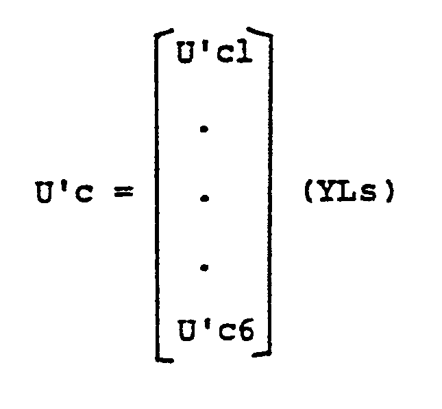
- variable factors U'c which are produced from the difference ⁇ 1, ⁇ 2 between the controlled variables and the target values dependent on the line speed YLs: are integrated to produce outputs: which can be used as manipulated variables .
- the line speed can be measured by a tachgenerator which measures the RPM of the withdrawal capstan 32.
- the outputs which are obtained by effecting feedback action on the measured variables dependent on the line speed may be added to the manipulated variables .
- the target values and the line speed may be subjected to feedforward action dependent on the line speed to produce outputs: which may be added to the manipulated variables.
- the elements in the matrices C, F, N dependent on the line speed are junctions variable with the line speed, and can be predetermined by the foregoing optimum control theory and simulation.
- the line speed can be incorporated in the control system such that when the line speed for the extruder changes, the extrusion line can be controlled by optimum control coefficients at that time. Stated otherwise, control is carried out by changing muntivariable control coefficients as the line speed increases or decreases. Where the line speed is not utilized, the characteristics of the extrusion line exceed the limiters L1 through L6 when the extrusion line is started (when the line speed is increased from zero to a preset speed), and are kept constant. When the line speed reaches a constant speed, the control remains the same irrespective of whether the line speed is utilized or not.
- the rate of elongation of the cable which is an important factor in the mechanical and electrical characteristics of communication cables may be used as one of controlled variables .
- the rate of elongation of the cable coated with the foamed insulation may be continuously measured, and based on the result of this measurement, the voltage applied to the annealer unit 14 may be controlled as a manipulation variable.
- the line speed may be added as one of the manipulated variables.
- the compound was supplied through the hopper 18 into the extruder, and the screw 20 was rotated about its own axis at 33 RPM.
- a cable conductor having a diameter of 0.4 mm was preheated by applying a constant voltage thereto, and was continuously fed into the crosshead of the extruder.
- the resin temperature C5 in the crosshead was 205°C
- the resin pressure P in the crosshead was 500 kg/cm2.
- the line speed was kept constantly at 2,000 m/m.
- a target outside diameter of the cable coated with foamed insulation was set up as 0.580 mm, and a target electrostatic capacity of the foamed insulation was established as 300 PF/m.
- the diameter D and electrostatic capacity C of the cable, the cylinder temperatures C3, C4 of the extruder, the crosshead temperature C6, the resin temperature C5 and the resin pressure P in the crosshead were measured, and the voltage applied to the preheater, the RPM of the screw in the extruder, the voltages applied to the cylinder heater units, the voltages applied to the crosshead heater units, and the distance between the movable water trough and the crosshead were manipulated to effect multivariable control in order to reach the target values. As shown in Fig.
- the outside diameter was controlled so as to fall in the range of ⁇ 1 micron of the target diameter (0.580 mm), and the electrostatic capacity C was controlled to fall in the range of ⁇ 1 PF/m of the target value (300 PF/m). Accordingly, a high-quality cable with foamed polyethylene insulation was fabricated.
- the outside diameter and the electrostatic capacity were selected to deviate ⁇ 5 microns and ⁇ 5 PF/m, respectively, from the target values, the controlled quantities were adjusted independently into the target values with high-speed responsiveness.
- Fig. 5 in the extrusion line to be controlled in which measured variables including controlled variables such as the outside diameter D and the electrostatic capacities C vary with a plurality of manipulated variables, manipulation variables obtained by the differences between controlled variables and target values are integrated and results are added to the manipulated variables when controlling the manipulated variables to adjust the controlled variables into conformity with the target values.
- the manipulated variables are thus capable of functioning mutually and independently. Multivariable control can be performed while allowing the controlled variables to approach the target values even when the control system is subjected to disturbances, with the result that high-quality of foamed insulation cables having desired outside diameter and electrostatic capacity can be manufactured.
- the control system has an increased response and stability with the feedforward action and/or the feedback action performed.
- Fig. 8 illustrates a control system in which a plurality of variables to be measured or measured variables: which comprises: variables to be controlled or controlled quantities (the outside diameter D and the electrostatic capacity C): of a cable extruded by the extrusion line 10 to be controlled, and condition variables affecting the controlled variables (cylinder temperatures C3, C4, a crosshead temperature C6, a resin temperature C5, and a resin pressure P) are varied by a plurality of variables to be manipulated or manipulated variables entered as input parameters (the RPM of the screw 20, the voltage applied to the preheater 16, the voltages applied to the cylinder heater units 23-3, 23-4, the voltages applied to the crosshead heater units 24-1 and 24-2, and the distance between the cooler unit 27 and the movable water trough 28) for changing the controlled variables:
- the control system controlls the manipulated variables so that the controlled variables will be adjusted to reach their target values: Designated at YL s0 is an input for a line speed to be set up.
- the controller CR in the control system as shown in Fig. 8 produced manipulated variables U1, U2 dependent on the line speed YLs, and the CPU effected multivariable control on the manipulated variables U1 through U6 based on the measured variables Y1 through Y7.
- Fig. 9 shows results of such multivariable control performed.
- One of the manipulated variables produced by the controller CR that is, the screw RPM, is also illustrated in Fig. 9.
- the line speed was increased, and the controller CR and the CPU started their controlling operation at a point a, and the line speed was again increased at a point b.
- the outside diameter D and the elestrostatic capacity C could be adjusted into their target values.
- the controller CR produces manipulated variables U1, U2 dependent on a measured variable, that is, the line speed YLs. This allows differences with desired manipulated variables, dependent on the line speed to be added to multivariable control outputs such as the manipulated variables U1 thorugh U6 issued from the CPU based on the measured variables Y1 through Y7. Since the manipulated variables by the controller CR and the CPU are complementary to each other, the electrostatic capacity C and the outside diameter D can be controlled so as to be constant at all times. Accordingly, cables having constant electrostatic capacity and outside diameter can be fabricated from the time when the line speed has just started to increase. Useless cables which would otherwise be produced are greatly reduced when the line speed begins to rise, and high-quality foamed insulation cables with their electrostatic capacity and outside diameter falling in the standard ranges can be manufactured.
- the line speed may also be added as one of the manipulated variables in the embodiment illustrated in Fig. 8.
- the given manipulated variables are controlled in proportion to a line speed, and manipulation variables obtained by the differences between controlled variables and target values are integrated and results are added to the manipulated variables when controlling the manipulated variables to adjust the controlled variables into conformity with the target values.
- the manipulated variables are thus capable of functioning mutually and independently. Multivariable control can be performed while allowing the controlled variables to approach the target values even when the control system is subjected to disturbances, with the result that high-quality of foamed insulation cables having desired outside diameter and electrostatic capacity can be manufactured.
Landscapes
- Engineering & Computer Science (AREA)
- Manufacturing & Machinery (AREA)
- Mechanical Engineering (AREA)
- Extrusion Moulding Of Plastics Or The Like (AREA)
Description
- The present invention relates to a system for controlling an extrusion line for foamed insulation cables, and more particularly to such a cable extrusion line control system with controlled variables such as the outside diameter and electrostatic capacity of formed insulation extruded and coated on the cable being multivariables.
- Communication cables are generally composed of a conductor with a coating of insulation extruded thereon having a small electrostatic capacitance and hence a small dielectric constant to meet the demand for a reduced transmission loss caused by the cable. The insulation is also required to support the cable itself. For these reasons, polyethylene foams (PEF) with a multiplicity of cells contained in polyethylenes are widely used as insulation for communication cables.
- Figs. 1 and 2 of the accompanying drawings illustrate an
extrusion line 10 for foamed insulation cables with insulation made of foamed polyolefin resins. Theextrusion line 10 has awire drawing unit 12 for elongating a dire rod 11 unwound from a wire stack 10a into acable conductor 13 having a smaller diameter than that of the wire rod , and anannealer unit 14 for annealing thecable conductor 13 with current annealing. - The
cable conductor 13 is then guided through afirst dancer roller 15 preferably to aninductive preheater 16 and thereafter continuously to anextruder 17. Thepreheater 16 serves to preheat thecable conductor 13 for allowing insulation which will be coated later to be uniformly foamed and also to be held in intimate contact with thecable conductor 13. Theextruder 17 has ahopper 18 through which a foaming insulation compound composed of a polyolefin resin and an organic foaming agent is supplied to theextruder 17. The supplied compound is forced into acrosshead 21 by ascrew 20 disposed in acylinder 19, as shown in Figs. 3 and 4. Thescrew 20 is driven by a motor 22 to rotate about its own axis. Acylinder heater 23 comprises a plurality of separate heater units 23-1 through 23-4 surrounding thecylinder 19. Thecrosshead 21 is heated by acrosshead heater 24 composed of a pair of crosshead heater units 24-1, 24-2. When thescrew 20 rotates, and thecylinder heater 23 and thecrosshead heater 24 are heated, the foaming insulation compound is heated at a temperature higher than the decomposition temperature of the foaming agent and is fed out from arestrictor 25 of thecrosshead 21 in a direction normal to the axis of therestrictor 25. The foaming insulation compound is then extruded and coated onto thecable conductor 13 at anipple 26. - Compressed gas contained in the foaming insulation compound under high pressure in the
extruder 17 is expanded in the compound when the compound is extruded into the atmosphere. The expanded gas forms cells in the compound which have maximum volumes when the pressure therein is equalized to the atmospheric pressure. By cooling the foamed insulation, the pressure in the cells is reduced to thereby allow the foamed insulation to shrink in volume. To effect such cooling, the extrusion line includes amovable cooler unit 27 comprising awater trough 29 with amovable water trough 28 slidably disposed at an upstream end thereof. The distance between themovable water trough 28 and the crosshead, particularly itsnipple 26, is adjusted to suppress the growth of chemical foaming in the insulation by water-cooling the latter in surrounding relation, and also to form a barrier on the outer peripheral surface of the resin for preventing foaming therein. The degree at which the foaming gas is expanded in the foamed insulation can thus be adjusted to gain a desired outside diameter and electrostatic capacity of the insulation. - The
cooler unit 27 may be immovable with the amount and temperature of water contained therein being controllably variable. - The
extrusion line 10 has an outside-diameter gage 30 for measuring the outside diameter of the insulation formed, and an electrostatic-capacity sensor 31 for measuring the electrostatic capacity of the insulation. The outside-diameter gage 30 may be a laser outside-diameter gage, type M501B, with the accuracy of 1 micron, manufactured by Anritsu Denki K.K., Japan. The electrostatic-capacity sensor 31 may be a sensor KI-700CGA (sensor KG 500) manufactured by BETA company,Bucks in High Wycombe, England, the sensor being capable of measuring the electrostatic capacity (PF/m) of the formed insulation cable with the accuracy of ± 0.1 PF/m. - In addition to the
above gage 30 and thesensor 31, theextruder 17 has a plurality of cylinder-temperature sensors TM1 through TM4, and thecrosshead 21 has a resin-temperature sensor TM5, a crosshead-temperature sensor TM6, and a resin-pressure gage PM (type CZ-1P manufactured by Rikagaku Kogyosha, Japan). - The formed insulation cable is drawn by a
withdrawal unit 32 and wound around a drum by acable winder 34 through asecond dancer roller 33. - In the manufacture of foamed insulation cables, it is necessary that the outside diameter (D) of the cable and the elestrostatic capacity (C) of the insulation be uniform in the longitudinal direction of the cable.
- To provide a desired outside diameter and electrostatic capacity through controlling the extrusion process on the
extrusion line 10, it has been customary practice to control the RPM of thescrew 20 in theextruder 17 and the voltage applied to thepreheater 16 in proportion to the speed at which the cable is withdrawn by thewithdrawal unit 32, that is, the line speed. - The elestrostatic capacity (C) has been controlled by moving the
movable water trough 28, while the outside diameter (D) has manually been ajusted. The manual adjustment of the outside diameter (D) has been carried out empirically by varying the RPM of theextruder screw 20 and the extruder temperature. In the actual practice, however, movement of themovable trough 28 results in a change in the electrostatic capacity and simultaneously in a change in the outside diameter. Although this control can control the electrostatic capacity at will, the outside diameter cannot be controlled since it undergoes a departure from the desired value. As a consequence, it has been quite difficult to control the electrostatic capacity and the outside diameter independently of each other with a view to manufacturing cables of high quality. - With the extrusion line of this type, a reduction in the RPM of the srew or an increase in the line speed while the extrusion temperature is kept constant results in a reduction in the outside diameter of the cable. When the extrusion temperature is increased, the expansion ratio of the insulation is increased and the outside diameter becomes larger. With the line speed going higher, the period of time required for the insulation to be cooled and solidified after extrusion is shortened, and hence the foaming process is finished early, resulting in a lower expansion ratio. Accordingly, these variable factors are related closely to each other. It is necessary to effect stable control of the outside diameter and electrostatic capacity (foaming ratio) while taking into account the correlation between these factors.
- In multivariable control, a multiplicity of measured variables, including, in the illustrated arrangement, the outside diameter D of the cable, the electrostatic capacity C of the insulation, which are controlled variables, temperatures C3, C4 indicated on the cylinder-temperature sensors TM3, TM4, a temperature C6 indicated on the crosshead-temperature sensor TM6, a temperatue C5 indicated on the resin-temperature sensor TM5, and a pressure P indicated on the resin-pressure gage PM, are varied when any one of a multiplicity of manipulated variables including, in the illustrated arrangement, the RPM of the
screw 20, the voltage applied to thepreheater 16, the voltages applied to the cylinder heater units 23-3, 23-4, the voltages applied to the crosshead heater units 24-1, 24-2, the distance between themovable water tank 28 and thecrosshead 21. With this type of multivariable control, it has conventionally been quite difficult by means of the measured variables to control the manipulated variables, simultaneously and automatically until the controlled variables reach desired values. - The control system in which the control variables and the manipulation variables are correlated in pairs cannot achieve quick response to and compensation for disturbances, with the consequences that the variables to be controlled are less stable and responsive. Since this control system does not control the electrostatic capacity C and the outside diameter D in response to the line speed, all of the products fabricated up to the point in which the line speed is rendered normal are useless. Furthermore, since the electrostatic capacity C and the outside diameter D are not constant until the resin temperature and the other temperatures are increased even during the normal operation, any cable manufactured before the required temperatures are reached is also useless. Therefore, the yield with the prior extrusion line has been poor.
- The above-described drawbacks in the prior art apparatus have been successfully eliminated by the present invention.
- It is the object of the present invention, which is defined in the accompanying claim, to provide an improved system for controlling an extrusion line for foamed insulation cables by simultaneously and automatically controlling variables to be manipulated in an extruder, a preheater and a cooler unit until variables to be controlled reach desired values (target settings) through detecting elements for detecting variables to be measured including such controlled variables as the outside diameter and electrostatic capacity of the cable, for thereby performing multivariable control of the extrusion line.
- This can be achieved by a multi variable control in which the number n of manipulated variables and the number m of the measured variables are greater than the
number 1 of controlled variables. Based on the conventional theory, the number of integrators had to be chosen equal to that of the reference signals. But if in this case there exists saturation in actuators, so-called wind-up phenomena cause a unstable response. According to the invention these undesirable situation is excluded by placing an integrator to each manipulating variable. The integrator is suspended from integrating action by a limiter, when the corresponding manipulating variable exceeds the boundary of the actuator. - The multi-variable control system being characterized in that a plurality of measured variables (where 1, n and m are positve integers with n, m ≧ 1 ≧2):

including firstly a plurality of controlled variables such as the outside diameter and the electrostatic capacity:
and secondly condition variables affecting the controlled variables , such as a cylinder temperature of the extruder, a crosshead temperature of the extruder, a resin temperature and a resin pressure in the crosshead, are variable in predetermined correlation with a plurality of manipulated variables as input parameters such as a line speed of the extrusion line, a voltage applied to a preheater disposed in front of the extruder, an RPM of a screw in the extruder, a voltage applied to a cylinder heater in the extruder, a voltage applied to a crosshead heater, and a distance which the cooler unit is movable:
The controlled variables being adjusted to approach the target values:
by manipulating the variables:
UC is determined in several function steps in the multi-variable control process. At first the differences between the target values and the controlled variables are calculated, the differences being multiplied with a weighing matrix C, yielding U'C:
- The matrix C is predetermined according to an optimisation method, which uses the extrusion line as a model and simulates the behaviour of the variables U and Y in regard of the target values YR.
- The resulting variables U'C being integrated and passed to summers, performing addition of feedforward values derived from YR and subtraction of feedback values derived from Y. The sums are applied to limiters, their outputs are the variables U, representing the control voltages of the actuators in the extrusion line. A limiter stops the foregoing integration action on a variable U'Ci as long as the output voltage Ui exceeds the boundary of the corresponding actuator.
- These objects of the invention will become apparent from the following description of embodiments together with the drawings.
- It is to be noted that a control system, for controlling an extrusion line for a foamed insulation cable, of the kind defined in the preamble of the claim is known from US 4 068 615.
-
- Figs. 1 and 2 are schematic side elevational and plan views of an extrusion line for foamed insulation cables which is to be controlled;
- Fig. 3 is an enlarged side elevational view, partly in cross section, of an extruder in the extrusion line shown in Figs. 1 and 2;
- Fig. 4 is an enlarged side elevational view, partly in cross section, of a crosshead in the extruder of Fig. 3;
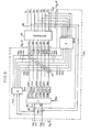
- Fig. 5 is a block diagram of an automatic multivariable control system according to the present invention for use in controlling the extrusion line of Figs. 1 and 2;
- Fig. 6 is a flowchart illustrative of operations of the control system shown in Fig. 5;
- Fig. 7 is a graph showing settings for variables to be controlled by the control system of Fig. 5 and results of its controlling operation;
- Fig. 8 is a block diagram of an automatic control system according to another embodiment for controlling the extrusion line; and
- Fig. 9 is a graph showing settings for variables to be controlled by the control system of Fig. 8 and results of its controlling operation.
- A system for controlling an extrusion line for foamed insulation cables according to the present invention will be described in detail with reference to Figs. 5 through 7 in which the control system is associated with the extrusion line shown in Figs. 1 and 2.
- In the control system illustrated in Fig. 5, a plurality of measured variables:

which comprises:
variables to be controlled or controlled variables (the outside diameter D and the electrostatic capacity C):
of a cable extruded by theextrusion line 10 to be controlled, and condition variables affecting the controlled variables (cylinder temperatures C3, C4, a crosshead temperature C6, a resin temperature C5, and a resin pressure P)
are varied by a plurality of variables to be manipulated or manipulated variables entered as input parameters (the RPM of thescrew 20, the voltage applied to thepreheater 16, the voltages applied to the cylinder heater units 23-3, 23-4, the voltages applied to the crosshead heater units 24-1 and 24-2, and the distance between thecooler unit 27 and the movable water tank 28) for changing the controlled variables:
The control system controls the manipulated variables so that the controlled variables will be adjusted to reach
The controlled variables Y1, Y2 are picked up at pick-off points 35 and delivered to subtractingpoints 36 in which the controlled variables are subtracted from the target values YR1, YR2 to produce differences therebetween as follows:
These differences ε1, ε2 are applied to an arithmetic element C which utilizes the matrix:
to produce variable factors U'c1 ... U'c5 by the following linear processing:
These variable factors are applied to integrators I1 through I6 in which ingegrating action is effected on the variable factors to produce manipulation variables Uc1-Uc6 which are then added to the manipulated variables U1 through U6. - These variables Uc can be expressed as a result of the integrating function performed, as follows:

The above integrating action includes not only linear integrating functions by the integrators, but integrating functions or similar actions. The integrating action may include dynamic compensation. The elements in the arithmetic element C:
are determined in an optimum manner by an optimum control theory with the controlled extrusion line as a model and by simulation of the behaviour of the variable factors U'c1 through U'c6, the manipulated variables U1 through U6, and the controlled variables Y1, Y2 at the time when the target values YR1, YR2 are given, prior to automatic control of theextrusion line 12. (Refer to "Control System Design for Furnace by Using CAD" by K, Furuta et al. at the IFAC Symposium on the Theory and Application of Digital Control, Delhi,Session 20, 1982) - The pick-off points 35 are connected to subtracting
points 37 through a feedback element F. The feedback element F effects feedback action through linear processing on the measured variables Y1 through Y7 including the controlled variables Y1, Y2, and the resulting outputs are subtractively added to the manipulated quantities U1 through U6. This feedback action may include dynamic compensation. Outputs UF from the feedback element F are as follows:
The elements:
can be predetermined by the foregoing optimum control theory and simulation. - Pick-off
points 38 are connected through a feedforward element N to summingpoints 37. The feedforward element N effects feedforward action or proportionality action on the target values YR1, YR2 and the line speed YLs by way of linear processing, and the resulting outputs are additionally applied to the manipulated variables U1 through U6. This feedforward action may include dynamic compensation. Outputs UN from the feedforward element N are as follows:
The elements:
can be determined as above by the optimum control theory and simulation. - Thus, three kinds of manipulation inputs are added to the manipulated variables U, which eventually be as follows:

- Manipulation lines include limiters L1 through L6 for stopping the foregoing integrating actions when the summed output:

exceeds a predetermined range. - A portion enclosed by the doted line in Fig. 5 represents a CPU which may be
TOSBAC 7/40 type manufactured by Tokyo Shibaura Denki, K.K., Japan, and includes an input/output device I/O-I as an input interface for the target values YR1, YR2, an input/output device I/O-2 as an output interface for D/A conversion of the manipulated variables U1 through U6, and an input/output device I/O-3 as an input interface for A/D convertion of the measured variables Y1 through Y7 including the controlled variables Y1, Y2 as they are fed back. - Operation of the automatic multivariable control system thus constructed is as follows:
- The
extrusion line 10 is first operated to determine initial settings for integrating actions dependent on the measured variables Y1 through Y7 including the controlled variables Y1, Y2. Then, the CPU reads data on the target values YR1, YR2, and the measured variables Y1 through Y7 including the controlled variables Y1, Y2. The arithmetic element C, the feedback element F and the feedforward element N in the CPU effect arithmetic operations according to the foregoing matrices to calculate the following values:

The manipulated variable outputs need to be controlled so as to be maintained within predetermined range. To this end, it is determined whether each manipulated variable output falls within such a predetermined range. If within the range, the integrating action is performed on the manipulated variable outputs, and if without the range, the manipulated variable outputs are caused to pass as outputs through the limiters L1 through L6 (See Fig. 6). Therefore, the integrators I1 through I6 are operated to effect integrating action on the variable factors U'c1 through U'c6 and produce the following integrated outputs:
- The above functions thus incorporated can overcome the problem of producing manipulated variable signals which are practically unsuitable for the manipulated variables due to initial large differences ε1 ... ε4 between the manipulated variables and the target values, notwithstanding the operation range for the inputs as the manipulated variables.
- The integrators repeat their integrating action until the difference between the target values and the controlled variables :

becomes zero, so that a control loop is formed to bring the controlled variables toward the target values as closely as possible. - The manipulated variables U:

are calculated and applied to the controlled system orextrusion line 10. - The feedback outputs UF from the feedback element F function to stabilize the characteristics inherent in the control system.
- The feedback outputs UN from the feedforward element N are effective to enable the controlled variables Y to approach the target values YR rapidly, especially at the start-up time of the
extrusion line 10. The feedforward element N thus serves to improve the response of the control system. - After the manipulated variables U have been delivered as outputs to the
extrusion line 10, operation of the control system is delayed for a predetermined time interval until next sampling is carried out. Then, the foregoing cycle of operation is repeated. - The variable factors U'c which are produced from the difference ε1, ε2 between the controlled variables and the target values dependent on the line speed YLs:
are integrated to produce outputs:
which can be used as manipulated variables . - The line speed can be measured by a tachgenerator which measures the RPM of the
withdrawal capstan 32. - The outputs which are obtained by effecting feedback action on the measured variables dependent on the line speed:
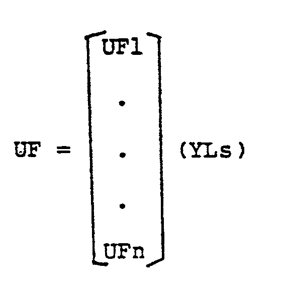
may be added to the manipulated variables . Likewise, the target values and the line speed:
may be subjected to feedforward action dependent on the line speed to produce outputs:
which may be added to the manipulated variables. - The elements in the matrices C, F, N dependent on the line speed are junctions variable with the line speed, and can be predetermined by the foregoing optimum control theory and simulation.
- The line speed can be incorporated in the control system such that when the line speed for the extruder changes, the extrusion line can be controlled by optimum control coefficients at that time. Stated otherwise, control is carried out by changing muntivariable control coefficients as the line speed increases or decreases. Where the line speed is not utilized, the characteristics of the extrusion line exceed the limiters L1 through L6 when the extrusion line is started (when the line speed is increased from zero to a preset speed), and are kept constant. When the line speed reaches a constant speed, the control remains the same irrespective of whether the line speed is utilized or not.
- In the illustrated embodiment, the rate of elongation of the cable which is an important factor in the mechanical and electrical characteristics of communication cables may be used as one of controlled variables . The rate of elongation of the cable coated with the foamed insulation may be continuously measured, and based on the result of this measurement, the voltage applied to the
annealer unit 14 may be controlled as a manipulation variable. Furthermore, the line speed may be added as one of the manipulated variables. - An example of the control system of the present invention will be described:
- A chemically foaming polyethylene compound was prepared in the form of pellets, the compound being composed of 100 parts by weight of high-density polyethylene (sold under the trade name "Hi-zex 5300E" by Mitsui Petrochemical Industries, Japan, with d = 0.95 and M.I. = 0.4) and 0.5 part by weight of azodicarbonamide as the chemical foaming agent. An extruder having a cylinder diameter of 65 mm as shown in Figs. 1 through 4 was used, and the cylinder was heated up to temperatures C1 = 155°C, C2 = 175°C, C3 = 190°C, C4 = 200°C and the crosshead was heated up to a temperature C6 = 200°C. The compound was supplied through the
hopper 18 into the extruder, and thescrew 20 was rotated about its own axis at 33 RPM. A cable conductor having a diameter of 0.4 mm was preheated by applying a constant voltage thereto, and was continuously fed into the crosshead of the extruder. At this time, the resin temperature C5 in the crosshead was 205°C, and the resin pressure P in the crosshead was 500 kg/cm². The line speed was kept constantly at 2,000 m/m. A target outside diameter of the cable coated with foamed insulation was set up as 0.580 mm, and a target electrostatic capacity of the foamed insulation was established as 300 PF/m. The diameter D and electrostatic capacity C of the cable, the cylinder temperatures C3, C4 of the extruder, the crosshead temperature C6, the resin temperature C5 and the resin pressure P in the crosshead were measured, and the voltage applied to the preheater, the RPM of the screw in the extruder, the voltages applied to the cylinder heater units, the voltages applied to the crosshead heater units, and the distance between the movable water trough and the crosshead were manipulated to effect multivariable control in order to reach the target values. As shown in Fig. 7, the outside diameter was controlled so as to fall in the range of ± 1 micron of the target diameter (0.580 mm), and the electrostatic capacity C was controlled to fall in the range of ± 1 PF/m of the target value (300 PF/m). Accordingly, a high-quality cable with foamed polyethylene insulation was fabricated. When the outside diameter and the electrostatic capacity were selected to deviate ± 5 microns and ± 5 PF/m, respectively, from the target values, the controlled quantities were adjusted independently into the target values with high-speed responsiveness. - With the embodiment of Fig. 5, in the extrusion line to be controlled in which measured variables including controlled variables such as the outside diameter D and the electrostatic capacities C vary with a plurality of manipulated variables, manipulation variables obtained by the differences between controlled variables and target values are integrated and results are added to the manipulated variables when controlling the manipulated variables to adjust the controlled variables into conformity with the target values. The manipulated variables are thus capable of functioning mutually and independently. Multivariable control can be performed while allowing the controlled variables to approach the target values even when the control system is subjected to disturbances, with the result that high-quality of foamed insulation cables having desired outside diameter and electrostatic capacity can be manufactured.
- The control system has an increased response and stability with the feedforward action and/or the feedback action performed.
- By incorporating the line speed into the control system, cables with their diameters and electrostatic capacities falling in a desired standard range can be fabricated even while the line speed is being on the increase. Accoridngly, nonstandard cables or useless cables will not be produced, and the extrusion line can have an increased yield.
- Fig. 8 illustrates a control system in which a plurality of variables to be measured or measured variables:

which comprises:
variables to be controlled or controlled quantities (the outside diameter D and the electrostatic capacity C):
of a cable extruded by theextrusion line 10 to be controlled, and condition variables affecting the controlled variables (cylinder temperatures C3, C4, a crosshead temperature C6, a resin temperature C5, and a resin pressure P)
are varied by a plurality of variables to be manipulated or manipulated variables entered as input parameters (the RPM of thescrew 20, the voltage applied to thepreheater 16, the voltages applied to the cylinder heater units 23-3, 23-4, the voltages applied to the crosshead heater units 24-1 and 24-2, and the distance between thecooler unit 27 and the movable water trough 28) for changing the controlled variables:
The control system controlls the manipulated variables so that the controlled variables will be adjusted to reach their target values: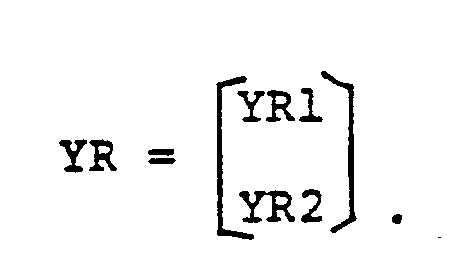
Designated at YLs0 is an input for a line speed to be set up. - When the line speed YLs as a measured variable is applied to a controller CR, the latter produces as outputs a screw RPM U1 and a preheater voltage U2 as manipulated variables dependent on the line speed. Then, as described above with reference to Fig. 5, the measured variables Y1 through Y7 are subjected to multivariable control in the CPU, which then generates manipulated variables U1 through U6 as outputs. The outputs U1, U2 from the controller CR and the CPU are connected in common.
- Another exmaple will be described below.
- Under the same con itions (except the line speed) as in Example 1, the controller CR in the control system as shown in Fig. 8 produced manipulated variables U1, U2 dependent on the line speed YLs, and the CPU effected multivariable control on the manipulated variables U1 through U6 based on the measured variables Y1 through Y7. Fig. 9 shows results of such multivariable control performed. One of the manipulated variables produced by the controller CR, that is, the screw RPM, is also illustrated in Fig. 9. The line speed was increased, and the controller CR and the CPU started their controlling operation at a point a, and the line speed was again increased at a point b. During an intervel in which the line speed increases from the point b up to a normal line speed, the outside diameter D and the elestrostatic capacity C could be adjusted into their target values.
- With the control system illustrated in Fig. 8, the controller CR produces manipulated variables U1, U2 dependent on a measured variable, that is, the line speed YLs. This allows differences with desired manipulated variables, dependent on the line speed to be added to multivariable control outputs such as the manipulated variables U1 thorugh U6 issued from the CPU based on the measured variables Y1 through Y7. Since the manipulated variables by the controller CR and the CPU are complementary to each other, the electrostatic capacity C and the outside diameter D can be controlled so as to be constant at all times. Accordingly, cables having constant electrostatic capacity and outside diameter can be fabricated from the time when the line speed has just started to increase. Useless cables which would otherwise be produced are greatly reduced when the line speed begins to rise, and high-quality foamed insulation cables with their electrostatic capacity and outside diameter falling in the standard ranges can be manufactured.
- The line speed may also be added as one of the manipulated variables in the embodiment illustrated in Fig. 8.
- With the arrangement of Fig. 8, in the extrusion line to be controlled in which measured variables including controlled variables such as the outside diameter D and the electrostatic capacities C vary with a plurality of manipulated variables , the given manipulated variables are controlled in proportion to a line speed, and manipulation variables obtained by the differences between controlled variables and target values are integrated and results are added to the manipulated variables when controlling the manipulated variables to adjust the controlled variables into conformity with the target values. The manipulated variables are thus capable of functioning mutually and independently. Multivariable control can be performed while allowing the controlled variables to approach the target values even when the control system is subjected to disturbances, with the result that high-quality of foamed insulation cables having desired outside diameter and electrostatic capacity can be manufactured.
- In the foregoing embodiments, two controlled variables , two target values, six manipulation variables, six manipulated variables, and seven measured variables have been described. The present invention is also applicable to instances in which the number of controlled quantities or target values, the number of maniuplation variables or manipulated variables , and the number of measured variables may be ℓ, n, and m, respectively (ℓ , n, and m are positive integers of 2 or greater with the relationship: n, m ≧ ℓ ).
Claims (1)
- A control system for controlling an extrusion line for a foamed insulation cable in which a foaming insulation compound composed of a polyolefin resin and a foaming agent are supplied to an extruder, and extruded and coated as a foamed insulation onto a continuously fed cable conductor at a temperature higher than a decomposition temperature of the foaming agent and subsequently passed through a cooler unit for controlling the outside diameter and the electrostatic capacity of the foamed insulation so as to attain the target values therefor; the control system comprising:a) means for detecting a plurality of measured variables Y₁, Y₂, ..., Yℓ, ..., Ym) including, firstly, a plurality of controlled variables including the outside diameter and electrostatic capacity Y(Y1, Y₂, ..., Yℓ) and , secondly, a cylinder temperature of the extruder, a crosshead temperature of the extruder, a resin temperature and a resin pressure in the crosshead affecting said controlled variables;b) means for manipulating a plurality of manipulated variables U(U₁, U₂, ..., Un) such as a line speed of the extrusion line, a voltage applied to a preheater disposed in front of the extruder, a rate of revolution of a screw in the extruder, a voltage applied to a cylinder heater, a voltage applied to a crosshead heater, and a distance which the cooler unit is movable, which manipulated variables vary said controlled variables, where the number 1 of said controlled variables, the number n of said manipulated variables and the number m of said measured variables are positive integers equal to or greater than 2;
characterized by:
said number n of said manipulated variables and said number m of said measured variables both being greater than said number ℓ of said controlled variables;c) arithmetic means storing a plurality of multiplication factors C (C₁₁ ... C1ℓ, ..., Cn1 ... Cnℓ) predetermined in accordance with a method of optimisation with the extrusion line as a model and by simulation of the behaviour of said manipulated variables U and said controlled variables Y for the given target values YR(YR1, YR2 ... YRℓ) of the controlled variables, said arithmetic means outputting a plurality of variable factors U'c (U'c1, ... U'cn) equal in number to said manipulated variables U, said variable factors U'c being derived from a multiplication by said multiplication factors of the difference values(YR-Y) between said given target values and the values of said controlled variables detected by said detecting means,d) a plurality of integrators (I₁ to I₆) for effecting an integrating action on respective ones of said variable factors U'c;e) a plurality of summing means (37) for receiving the outputs of respective ones of said plurality of integrators (I₁ to I₆);f) feedback means (F) conected to said detecting means to receive the measured values of said plurality of meansured variables, said feedback means (F) supplying a signal to each of said plurality of summing means (37);g) a plurality of limiter means (L₁ to L₆) connected to respective ones of said plurality of summing means (37) for suspending the integrating action of the respective integrator when the value of the integrator output minus the value of the respective feedback signal, the difference being calculated by the respective summing means, exceeds a predetermined value, the output of said plurality of limiter means being said plurality of manipulated variables (U), whereby the manipulated variables are controlled so that the outside diameter and the electrostatic capacity of the foamed insulation attain the target values therefor.
Applications Claiming Priority (4)
| Application Number | Priority Date | Filing Date | Title |
|---|---|---|---|
| JP40544/82 | 1982-03-15 | ||
| JP57040543A JPS58175217A (en) | 1982-03-15 | 1982-03-15 | Extrusion line control system for foamable insulated wire |
| JP57040544A JPS58175218A (en) | 1982-03-15 | 1982-03-15 | Extrusion line control system for foamable insulated wire |
| JP40543/82 | 1982-03-15 |
Publications (3)
| Publication Number | Publication Date |
|---|---|
| EP0089060A2 EP0089060A2 (en) | 1983-09-21 |
| EP0089060A3 EP0089060A3 (en) | 1986-02-05 |
| EP0089060B1 true EP0089060B1 (en) | 1991-09-11 |
Family
ID=26380017
Family Applications (1)
| Application Number | Title | Priority Date | Filing Date |
|---|---|---|---|
| EP83102559A Expired - Lifetime EP0089060B1 (en) | 1982-03-15 | 1983-03-15 | System for controlling an extrusion line for foamed insulation cables |
Country Status (3)
| Country | Link |
|---|---|
| US (1) | US4585603A (en) |
| EP (1) | EP0089060B1 (en) |
| DE (1) | DE3382405D1 (en) |
Cited By (1)
| Publication number | Priority date | Publication date | Assignee | Title |
|---|---|---|---|---|
| AT410610B (en) * | 1999-03-18 | 2003-06-25 | Uniline Kabelmaschb Und Handel | METHOD FOR THE CONTINUOUS PRODUCTION OF COATED CABLES AND DEVICE FOR IMPLEMENTING THE METHOD |
Families Citing this family (31)
| Publication number | Priority date | Publication date | Assignee | Title |
|---|---|---|---|---|
| FR2565887A1 (en) * | 1984-06-14 | 1985-12-20 | Ems Extrusion | Continuous vulcanisation and/or crosslinking line, especially for producing insulating synthetic layers on cables |
| GB8505199D0 (en) * | 1985-02-28 | 1985-04-03 | Bicc Plc | Extrusion control |
| EP0218850A1 (en) * | 1985-09-25 | 1987-04-22 | Kunststoff-Verarbeitungs GmbH Dirk A. Brügmann | Process for determining a proportional change in a profile |
| DE3782058T2 (en) * | 1986-07-12 | 1993-04-15 | Fly Fishing Techn Ltd | METHOD AND DEVICE FOR PRODUCING FISHING LINE. |
| AU1712088A (en) * | 1987-04-15 | 1988-11-04 | Dow Chemical Company, The | A method of extruding an alkenyl aromatic synthetic resin foamed body having closed cells |
| GB8729436D0 (en) * | 1987-12-17 | 1988-02-03 | Univ Strathclyde | Process control system |
| US5155677A (en) * | 1989-11-21 | 1992-10-13 | International Business Machines Corporation | Manufacturing process optimizations |
| JPH0739128B2 (en) * | 1991-03-29 | 1995-05-01 | 鬼怒川ゴム工業株式会社 | Controller for continuous extrusion vulcanization line |
| JP3093518B2 (en) * | 1993-06-02 | 2000-10-03 | 株式会社神戸製鋼所 | Control method of metal wire coating equipment |
| FI94989C (en) * | 1993-12-31 | 1995-11-27 | Maillefer Nokia Holding | secondary coating |
| US6116882A (en) * | 1996-08-14 | 2000-09-12 | Owens Corning Fiberglas Technology, Inc. | Sealable chamber extrusion apparatus with seal controls |
| US5753161A (en) * | 1996-08-14 | 1998-05-19 | Owens-Corning Fiberglas Technology, Inc. | Vacuum extrusion system and method |
| US6093350A (en) * | 1996-08-14 | 2000-07-25 | Owens Corning Fiberglas Technology, Inc. | Sealable chamber extrusion apparatus and method with process controls |
| US6036468A (en) | 1997-08-21 | 2000-03-14 | Owens Corning Fiberglas Technology, Inc. | Vacuum extrusion system |
| US6517722B1 (en) * | 1998-01-28 | 2003-02-11 | James Benenson, Jr. | Self cleaning fuel oil strainer |
| ES2300314T3 (en) | 2001-06-19 | 2008-06-16 | Maillefer S.A. | CAPACITY REGULATION PROCEDURE. |
| US8557884B2 (en) * | 2002-05-31 | 2013-10-15 | Owens Corning Intellectual Capital, Llc | To enhance the thermal insulation of polymeric foam by reducing cell anisotropic ratio and the method for production thereof |
| BRPI0607914A2 (en) * | 2005-02-25 | 2010-03-23 | Nova Chem Inc | composite building panel, method for building a building, building, method for doing business between a composite building panel manufacturer and a customer, and, frame rafter |
| MX2007009959A (en) * | 2005-02-25 | 2007-09-26 | Nova Chem Inc | Lightweight compositions and articles containing such. |
| US8752348B2 (en) * | 2005-02-25 | 2014-06-17 | Syntheon Inc. | Composite pre-formed construction articles |
| MX2007011640A (en) | 2005-03-22 | 2008-01-18 | Nova Chem Inc | Lightweight concrete compositions. |
| US20080099942A1 (en) * | 2006-10-26 | 2008-05-01 | Shipman Yvette M | Automatic ramping method and system for extrusion coating wire |
| US7677009B2 (en) * | 2007-02-02 | 2010-03-16 | Nova Chemicals Inc. | Roof truss system |
| US8048219B2 (en) * | 2007-09-20 | 2011-11-01 | Nova Chemicals Inc. | Method of placing concrete |
| US20090078161A1 (en) * | 2007-09-20 | 2009-03-26 | Nova Chemicals Inc. | Methods of minimizing concrete cracking and shrinkage |
| US9592528B2 (en) | 2015-04-22 | 2017-03-14 | Delphi Technologies, Inc. | Extruding machine |
| CN109016319B (en) * | 2018-07-20 | 2020-09-04 | 滁州市玉林聚氨酯有限公司 | Polyurethane foaming device and using method thereof |
| CN114527721B (en) * | 2022-04-25 | 2022-08-12 | 广东祥利科技有限公司 | On-line production monitoring method, system and cloud platform for poly-PVC modified cable pellets |
| CN114986849A (en) * | 2022-06-02 | 2022-09-02 | 昆山捷嵘发测控设备有限公司 | Cable high-frequency preheater and preheating method |
| CN115440441B (en) * | 2022-09-16 | 2025-03-11 | 上海胜华(集团)宁夏电缆有限公司 | A processing device for cable production and a processing method thereof |
| CN119238918A (en) * | 2024-10-14 | 2025-01-03 | 广东华新电缆实业有限公司 | Control method, system, device and extrusion equipment of cable extrusion equipment |
Family Cites Families (22)
| Publication number | Priority date | Publication date | Assignee | Title |
|---|---|---|---|---|
| US3473008A (en) * | 1964-06-12 | 1969-10-14 | Leeds & Northrup Co | System for feed blending control |
| CH462910A (en) * | 1967-02-13 | 1968-09-30 | Gen Cable Corp | Method and device for applying layers of plastic to an electrical conductor |
| US3714952A (en) * | 1971-03-24 | 1973-02-06 | Foxboro Co | Pressure relief valve |
| US3941534A (en) * | 1971-11-01 | 1976-03-02 | Hunkar Laboratories, Inc. | Injection molding control system |
| US3890078A (en) * | 1972-01-31 | 1975-06-17 | Industrial Nucleonics Corp | Noninteracting extruder control |
| US4017228A (en) * | 1973-01-04 | 1977-04-12 | Western Electric Company, Inc. | Apparatus for monitoring cellular dielectric material |
| DE2403932A1 (en) * | 1973-01-29 | 1974-08-01 | Ceskoslovenska Akademie Ved | PROCEDURE AND ARRANGEMENT FOR SELF-ADJUSTING DIGITAL RULES |
| GB1459190A (en) * | 1973-04-04 | 1976-12-22 | British Petroleum Co | Blending |
| US3914356A (en) * | 1974-03-28 | 1975-10-21 | Western Electric Co | Methods of and apparatus for controlling the thickness of an annular extrusion |
| US4344142A (en) * | 1974-05-23 | 1982-08-10 | Federal-Mogul Corporation | Direct digital control of rubber molding presses |
| US4260351A (en) * | 1975-11-04 | 1981-04-07 | Hitachi Cables, Ltd. | Apparatus for producing foamed plastic insulated wires |
| US4088430A (en) * | 1976-03-12 | 1978-05-09 | Phillips Petroleum Company | Automatic control of extrusion |
| CA1087712A (en) * | 1976-11-01 | 1980-10-14 | Northern Telecom Limited | Control for wire coating line |
| US4174236A (en) * | 1977-08-31 | 1979-11-13 | Western Electric Company, Inc. | Methods of and apparatus for controlling capacitance unbalance-to-ground in cables |
| FI65504C (en) * | 1978-01-02 | 1984-05-10 | Nokia Oy Ab | METHOD OF ADJUSTMENT AV ENCLOSURE INSULATION LED CAPACITY WITH DIAMETER I SAMBAND MED TILLVERKNINGEN |
| JPS54122892A (en) * | 1978-02-28 | 1979-09-22 | Furukawa Electric Co Ltd:The | Method of and apparatus for manufacturing foam insulation electric cable |
| GB2019608B (en) * | 1978-04-13 | 1982-10-20 | Toshiba Machine Co Ltd | Controlling injection moulding |
| FR2426934A1 (en) * | 1978-05-26 | 1979-12-21 | Elf Union | Prodn. of mixt. of prods. - incorporating repetitive analyses and automatic regulation of mixt. of prods. in line e.g. of petroleum prods., avoiding interruption |
| US4298887A (en) * | 1980-06-09 | 1981-11-03 | Rockwell International Corporation | Non-uniformity correction in a multielement detector array |
| US4399105A (en) * | 1981-03-30 | 1983-08-16 | The Upjohn Company | Programmable computer controlled reaction injection mixing head system |
| US4359436A (en) * | 1981-04-29 | 1982-11-16 | Western Electric Company, Inc. | Methods of and systems for controlling the expansion of cellular plastic insulation in the manufacture of insulated conductors |
| US4406399A (en) * | 1981-07-28 | 1983-09-27 | Showa Electric Wire & Cable Co., Ltd. | Method of controlling an enamelling oven |
-
1983
- 1983-03-08 US US06/473,506 patent/US4585603A/en not_active Expired - Lifetime
- 1983-03-15 EP EP83102559A patent/EP0089060B1/en not_active Expired - Lifetime
- 1983-03-15 DE DE8383102559T patent/DE3382405D1/en not_active Expired - Lifetime
Cited By (1)
| Publication number | Priority date | Publication date | Assignee | Title |
|---|---|---|---|---|
| AT410610B (en) * | 1999-03-18 | 2003-06-25 | Uniline Kabelmaschb Und Handel | METHOD FOR THE CONTINUOUS PRODUCTION OF COATED CABLES AND DEVICE FOR IMPLEMENTING THE METHOD |
Also Published As
| Publication number | Publication date |
|---|---|
| EP0089060A3 (en) | 1986-02-05 |
| EP0089060A2 (en) | 1983-09-21 |
| DE3382405D1 (en) | 1991-10-17 |
| US4585603A (en) | 1986-04-29 |
Similar Documents
| Publication | Publication Date | Title |
|---|---|---|
| EP0089060A2 (en) | System for controlling an extrusion line for foamed insulation cables | |
| EP0197647B1 (en) | Control apparatus for extruders | |
| US4197070A (en) | Apparatus for controlling a plastic extruder | |
| US4290986A (en) | Method for controlling a plastic extruder | |
| EP0429959B1 (en) | Apparatus for controlling a heating temperature | |
| EP0400310B1 (en) | Device for controlling the external diameter of a cord, especially of a cable | |
| DE69028054T2 (en) | Adaptive process control system, especially for temperature control for flowing liquids | |
| GB1591534A (en) | Apparatus for the manufacture of plastics insulated wire | |
| DE60006713T2 (en) | METHOD FOR CONTROLLING THE GROWTH OF A SEMICONDUCTOR CRYSTAL | |
| CN1020767C (en) | Method and equipment for manufacturing silicon single crystal | |
| US4258003A (en) | Automatic control of crystal growth | |
| CN118769515A (en) | A multifunctional extruder for producing plastic protective tubes | |
| EP0615961B1 (en) | Method and apparatus for detecting an irregular portion of an optical fiber | |
| US3626479A (en) | Continuous casting machine with channel coolant control means | |
| US4358821A (en) | Method and apparatus for the incorporation of varying flow in the control of process quantities | |
| EP0542177B1 (en) | Film thickness controller | |
| US4032389A (en) | Apparatus for automatically controlling crystal growth | |
| US4359436A (en) | Methods of and systems for controlling the expansion of cellular plastic insulation in the manufacture of insulated conductors | |
| CN104003605A (en) | Methods for making a glass material and apparatus | |
| US4089923A (en) | Manufacture of submarine cable | |
| JPS6113331B2 (en) | ||
| JPS6113330B2 (en) | ||
| KR102051024B1 (en) | Ingot growing temperature controller and ingot growing apparatus with it | |
| JP2907719B2 (en) | Method and apparatus for producing foamed insulated wire | |
| JP2825592B2 (en) | Control equipment for metal wire coating equipment |
Legal Events
| Date | Code | Title | Description |
|---|---|---|---|
| PUAI | Public reference made under article 153(3) epc to a published international application that has entered the european phase |
Free format text: ORIGINAL CODE: 0009012 |
|
| AK | Designated contracting states |
Designated state(s): DE FR GB IT |
|
| PUAL | Search report despatched |
Free format text: ORIGINAL CODE: 0009013 |
|
| AK | Designated contracting states |
Designated state(s): DE FR GB IT |
|
| 17P | Request for examination filed |
Effective date: 19860727 |
|
| 17Q | First examination report despatched |
Effective date: 19880129 |
|
| GRAA | (expected) grant |
Free format text: ORIGINAL CODE: 0009210 |
|
| AK | Designated contracting states |
Kind code of ref document: B1 Designated state(s): DE FR GB IT |
|
| ITF | It: translation for a ep patent filed | ||
| REF | Corresponds to: |
Ref document number: 3382405 Country of ref document: DE Date of ref document: 19911017 |
|
| ET | Fr: translation filed | ||
| PLBE | No opposition filed within time limit |
Free format text: ORIGINAL CODE: 0009261 |
|
| STAA | Information on the status of an ep patent application or granted ep patent |
Free format text: STATUS: NO OPPOSITION FILED WITHIN TIME LIMIT |
|
| 26N | No opposition filed | ||
| PGFP | Annual fee paid to national office [announced via postgrant information from national office to epo] |
Ref country code: FR Payment date: 19980220 Year of fee payment: 16 |
|
| PGFP | Annual fee paid to national office [announced via postgrant information from national office to epo] |
Ref country code: GB Payment date: 19980223 Year of fee payment: 16 |
|
| PGFP | Annual fee paid to national office [announced via postgrant information from national office to epo] |
Ref country code: DE Payment date: 19980327 Year of fee payment: 16 |
|
| PG25 | Lapsed in a contracting state [announced via postgrant information from national office to epo] |
Ref country code: GB Free format text: LAPSE BECAUSE OF NON-PAYMENT OF DUE FEES Effective date: 19990315 |
|
| GBPC | Gb: european patent ceased through non-payment of renewal fee |
Effective date: 19990315 |
|
| PG25 | Lapsed in a contracting state [announced via postgrant information from national office to epo] |
Ref country code: FR Free format text: LAPSE BECAUSE OF NON-PAYMENT OF DUE FEES Effective date: 19991130 |
|
| REG | Reference to a national code |
Ref country code: FR Ref legal event code: ST |
|
| PG25 | Lapsed in a contracting state [announced via postgrant information from national office to epo] |
Ref country code: DE Free format text: LAPSE BECAUSE OF NON-PAYMENT OF DUE FEES Effective date: 20000101 |