EP0089036B1 - Verfahren zum Reinigen von Abgasen und zur Rückgewinnung von Wärme und Vorrichtung zur Durchführung des Verfahrens - Google Patents
Verfahren zum Reinigen von Abgasen und zur Rückgewinnung von Wärme und Vorrichtung zur Durchführung des Verfahrens Download PDFInfo
- Publication number
- EP0089036B1 EP0089036B1 EP83102457A EP83102457A EP0089036B1 EP 0089036 B1 EP0089036 B1 EP 0089036B1 EP 83102457 A EP83102457 A EP 83102457A EP 83102457 A EP83102457 A EP 83102457A EP 0089036 B1 EP0089036 B1 EP 0089036B1
- Authority
- EP
- European Patent Office
- Prior art keywords
- waste gas
- stack
- scrubbing fluid
- scrubbing
- storage vessel
- Prior art date
- Legal status (The legal status is an assumption and is not a legal conclusion. Google has not performed a legal analysis and makes no representation as to the accuracy of the status listed.)
- Expired
Links
Images

Classifications
-
- F—MECHANICAL ENGINEERING; LIGHTING; HEATING; WEAPONS; BLASTING
- F23—COMBUSTION APPARATUS; COMBUSTION PROCESSES
- F23J—REMOVAL OR TREATMENT OF COMBUSTION PRODUCTS OR COMBUSTION RESIDUES; FLUES
- F23J15/00—Arrangements of devices for treating smoke or fumes
- F23J15/02—Arrangements of devices for treating smoke or fumes of purifiers, e.g. for removing noxious material
- F23J15/04—Arrangements of devices for treating smoke or fumes of purifiers, e.g. for removing noxious material using washing fluids
-
- F—MECHANICAL ENGINEERING; LIGHTING; HEATING; WEAPONS; BLASTING
- F24—HEATING; RANGES; VENTILATING
- F24D—DOMESTIC- OR SPACE-HEATING SYSTEMS, e.g. CENTRAL HEATING SYSTEMS; DOMESTIC HOT-WATER SUPPLY SYSTEMS; ELEMENTS OR COMPONENTS THEREFOR
- F24D2200/00—Heat sources or energy sources
- F24D2200/16—Waste heat
- F24D2200/18—Flue gas recuperation
Definitions
- the invention relates to a method for purifying exhaust gas and recovering heat, in particular from a combustion system, in which the exhaust gas is brought into contact with a circulating scrubbing liquid coming from a storage tank, which contains additives which bind pollutants contained in the exhaust gas.
- the washing liquid simultaneously removes heat from the exhaust gas and in which the compounds formed in the washing liquid are oxidized and removed from the circuit.
- the invention also relates to an apparatus for performing the method.
- Firing systems in which fossil fuels are burned pollute the environment through pollutants carried in the exhaust gas, in particular sulfur dioxide SO 2 .
- pollutants carried in the exhaust gas in particular sulfur dioxide SO 2 .
- the hot exhaust gases result in high heat losses. This heat of loss means that the overall efficiency of a combustion system, in which water is heated, for example, is limited and the use of the energy used is therefore unsatisfactory.
- the scrubbing liquid expediently circulated for this purpose contains appropriate chemicals, such as calcium carbonate and / or calcium oxide and / or calcium hydroxide, which bind the sulfur dioxide in the exhaust gas.
- the compounds formed are then oxidized to calcium sulfate by oxygen and this is separated from the wash water and removed.
- the method known from US-A-3 386 798 is also designed for a large-scale system, with a cleaning device being arranged between a combustion system and a chimney.
- the cleaned exhaust gas reaches the lower area of the chimney.
- the exhaust gases coming from the burner or boiler flow through a line through an air preheater and dust collector and are introduced from here into the upper area of a cleaning chamber of a gas cleaner equipped with a heat exchanger fill.
- the washing liquid is sprayed into the cleaning chamber of the gas cleaner from the gas inlet side, ie in the same direction of flow as the gas.
- the scrubbing liquid enriched with the pollutants bound from the exhaust gases returns to the circuit via a liquid collector and the cleaned exhaust gases are introduced from the cleaning chamber into the lower area of the chimney.
- DE-A-2 512 233 discloses a method and a device for heat recovery from the flue gases of fuel-fired boilers.
- a liquid intermediate medium is heated with the flue gases emerging from the boiler and the water entering the boiler is preheated by heat exchange with the intermediate medium.
- the boiler is combined with a preheating vessel filled with water in the lower area, which has a flue gas inlet directly above the water level and a flue gas outlet in the upper area. Exhaust gas cleaning is not provided in this device.
- the object of the invention is to provide a method of the type mentioned and a device suitable for carrying out the method, with a minimum expenditure in terms of equipment and exhaust gas purification in an extremely economical manner, even in small and medium-sized incineration plants, with extensive leaching the substances that pollute the exhaust gases and, at the same time, heat recovery and the corresponding energy-saving use of the fuels.
- the device for carrying out the method which has a storage container for the washing liquid and an inlet line leading to a cleaning chamber and a return line for the washing liquid leading from this cleaning chamber, and furthermore an inlet line for exhaust gas leading from the boiler room of a boiler of the firing system into the cleaning chamber , is characterized in that the inlet line leads from the boiler into the lower region of the cleaning chamber, the cleaning chamber through the chimney itself or through a arranged in the chimney, essentially taking up its entire length, an exhaust line leading from the storage container for washing liquid opens into an upper region of the cleaning chamber, and in the bottom region of the cleaning chamber a drain line leading back into the storage container is provided.
- the process has a number of advantages, which range from being carried out in a space-saving arrangement for small and medium-sized plants to removing pollutants and simultaneously utilizing heat.
- One of the essential features is the inclusion of the fireplace in the work area of the washing process.
- the space requirement of the entire system is thus reduced to a minimum, and it is also achieved that, at the same time, the scrubbing liquid flowing in countercurrent not only removes pollutants from the exhaust gas but also heat which can now be supplied to a fluid to be heated.
- the device adapted to the method offers yet another possibility for heat utilization, which can be implemented without great effort.
- a heat exchanger can be installed in a connecting pipe, for example a chimney socket between the boiler and the flue gas pipe in the chimney, which already extracts part of the heat that is usually lost by the exhaust gas escaping here, so that this heat can be used for any purpose can be.
- the additional device from a combined storage-sedimentation tank and optionally reaction tank brings further advantages, since the solid compounds washed out with the washing water and formed by the further treatment settle during the standstill periods of the burner. When the burner is out of operation, the washing liquid circulation is also switched off. The fine solids, because these are usually, are deposited in the storage tank from the dormant washing liquid and are only sporadically removed from here during downtimes.
- the separation is more complete than when the solids are withdrawn during the liquid circulation, as is the case with known methods and systems.
- This measure also simplifies and improves the method according to the invention compared to the prior art.
- the heat of condensation of the combustion gases can only be optimally used if liquid, usually water, actually condenses out.
- the amount of heat extracted from the washing liquid is regulated in such a way that the temperature of the liquid is partly below and partly above the dew point of the flue gases or exhaust gases.
- moisture from the exhaust gases is condensed into the wash water and, on the other hand, water from the wash water is evaporated into the smoke or exhaust gases.
- the amount of heat withdrawn from the washing liquid via heat exchangers is expediently regulated via a level switch assigned to the storage tank, and thus the temperature and the amount of the washing liquid are controlled.
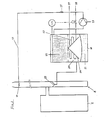
- FIG. 1 schematically shows a conventional oil burner 1 of a firing system arranged in a boiler 2, which is connected downstream of the washing system.
- the boiler 2 which is used, for example, for heating domestic and heating water, is equipped with a domestic water supply 3 and a domestic water feed line 4 as well as a heating supply 5 and a heating return 6.
- the boiler 2 is connected to a chimney 8, which is bricked, but can also be designed only as a jacket for an exhaust pipe 9.
- This exhaust pipe 9 is an essential part of the device for carrying out the washing process. It leads from the lower region of the chimney 8 upwards, preferably essentially through the entire length of the chimney 8 and is from the Exhaust gases flowing from oil burner 1.
- a storage container 16 is provided outside the chimney 8, expediently at its lower end, from which a line 12 for the wash water opens into an upper region in the exhaust line 9.
- a pump 13 is installed in the line 12 and then an air injector 15 is installed thereon.
- the entry of line 12 into exhaust line 9 is preferably provided with a spray device 10, which advantageously has spray arms 11 arranged in a star shape.
- a drain line 14 leads back to the storage tank 16 from a lower area of the exhaust gas line 9 which is closed off from the outside. The washing liquid is injected from the storage container 16 into the exhaust pipe 9 with the aid of the pump 13.
- a practical embodiment provides an exhaust pipe 9 with a length at least corresponding to the chimney height, advantageously 6 m or more.
- the diameter of such an exhaust pipe 9 is approximately 15 cm.
- a scrubbing liquid which binds pollutants in the exhaust gas is preferably a lime solution in which burnt lime and water are present in a ratio of 40 g of lime to 1 liter of water and formic acid in a ratio of 50 g of formic acid to 40 g of lime.
- Air is introduced into the wash water downstream of the pump 13 in the line 12, for example through the air injector 15, in order to carry out the required oxidation in the solution.
- the process water feed 17 is passed through the storage tank 16 and passes into the process water feed line 4, which enters the boiler 2.
- the return 18 of the heating water also leads through the storage tank 16 and from here to the heating return 6, which opens into the boiler 2.
- a heat exchanger 7 In the connection between the boiler 2 and the exhaust pipe 9, which is preferably designed as a chimney nozzle 19, a heat exchanger 7 is used, which removes this heat as soon as the exhaust gases coming from the boiler 2 enter.
- the medium heated in the heat exchanger can be used for any purpose.
- the design of the storage container 16 also contributes to the optimal implementation of the method according to the invention, which can be designed in such a way that not only the washing liquid is stored here, but the solids fall down therein and are collected during the shutdown of the combustion system. Furthermore, this storage container 16 can also be equipped with a reaction chamber.
- a combined storage, sedimentation and reaction container 16 is shown schematically in FIG.
- the boiler 2 of the firing system and the chimney 8 in which the exhaust pipe 9 (FIG. 1) is guided and into which the pipe 12 for the washing liquid coming from the storage tank 16 opens are shown here.
- the storage, sedimentation and reaction container 16 consists of three departments, namely the chamber 20 for the washing liquid flowing back from the exhaust pipe 9 via the drain pipe 14. Below this chamber 20 is the sludge chamber 21 and above the chamber 20 there is a storage chamber 22 filled with calcium carbonate (CaC0 2 ). In the chamber 20 there is a heat exchanger 23, for example for process water, into which the inlet and outlet lines 17 , 18 lead for a medium that is used for heat recovery.
- the pump 13 is arranged in the lower region of the line 12 leading into the exhaust gas line 9 for the washing water and the air injector 15 is arranged downstream Flow of the medium for heat recovery is provided.
- the setting is such that the temperature of the scrubbing liquid is partly below and partly above the dew point of the exhaust gases, so that either moisture from the exhaust gases condenses into the washing water or water from the washing water evaporates into the exhaust gases.
- Level switches of this type are known.
- the resulting exhaust gas in the oil burner 1 contains S0 2 , which is known to produce up to about 3 liters of S0 2 gas when burning 1 kg of oil. This sulfur gas, which pollutes the environment, should and must be removed.
- the exhaust gas flowing through the chimney nozzle 19, which is hot up to about 300 ° C., is first cooled by the heat exchanger 7 located in this feed line. This is preferably designed such that the exhaust gas is cooled to, for example, 50 to 80 ° C. At this temperature, the exhaust gas reaches the exhaust pipe 9. -
- the heat exchanger 7 can be flowed through by water that heats up through heat exchange and this warm water can be used for various purposes, such as for building heating, domestic water heating, swimming pool heating and the like.
- the exhaust gas cooled in the first heat exchanger 7 flows upward in the exhaust line 9, counter to the washing liquid which contains a calcium format and flows through the spray device 10 from top to bottom in the exhaust line 9.
- the gas contained in the exhaust gas reacts during this counterflow. Sulfur dioxide with the Ca 2+ ions of the washing liquid.
- Free formic acid is formed in accordance with the Ca 2 + ions bound by the sulfur dioxide. Reacts on the way of the washing liquid through the combined storage, sedimentation and reaction container 16 (FIG. 2) this free formic acid with the calcium carbonate in the storage space 22. In accordance with the free formic acid formed in the exhaust line 9, Ca 2 + ions are dissolved from the calcium carbonate, so that a regenerated washing solution is supplied to the exhaust line 9.
- a detergent funnel 25 (FIG. 2) is expediently provided, from which the washing liquid enriched with bound sulfur dioxide from the exhaust gas reaches the chamber 20 of the combined storage tank 16 via the drain line 14.
- the calcium sulfate (gypsum) formed during the absorption of the sulfur dioxide under atmospheric oxygen settles on the bottom of the sedimentation container, that is to say in its sludge chamber 21, in particular during the burner downtimes, in which the circulation of the washing liquid is also switched off.
- the sludge layer is expediently covered by a cover funnel 24 opposite the remaining container space in order not to whirl up any settled sludge during the washing liquid circulation. At the bottom of the sludge space 21, the settled solid can be drawn off in corresponding periods.
- the sulfur dioxide content in exhaust gases can also be largely removed in small and medium-sized combustion plants, with substantial amounts of heat being recovered by heat exchange in two stages, namely before the washing process and during the washing process and can be used.
- the washing liquid can also be regenerated in whole or in part.
Landscapes
- Engineering & Computer Science (AREA)
- Mechanical Engineering (AREA)
- General Engineering & Computer Science (AREA)
- Treating Waste Gases (AREA)
- Separation By Low-Temperature Treatments (AREA)
- Exhaust Gas Treatment By Means Of Catalyst (AREA)
- Central Heating Systems (AREA)
- Steam Or Hot-Water Central Heating Systems (AREA)
- Filling Or Discharging Of Gas Storage Vessels (AREA)
Priority Applications (1)
| Application Number | Priority Date | Filing Date | Title |
|---|---|---|---|
| AT83102457T ATE20493T1 (de) | 1982-03-16 | 1983-03-12 | Verfahren zum reinigen von abgasen und zur rueckgewinnung von waerme und vorrichtung zur durchfuehrung des verfahrens. |
Applications Claiming Priority (2)
| Application Number | Priority Date | Filing Date | Title |
|---|---|---|---|
| CH164782 | 1982-03-16 | ||
| CH1647/82 | 1982-03-16 |
Publications (2)
| Publication Number | Publication Date |
|---|---|
| EP0089036A1 EP0089036A1 (de) | 1983-09-21 |
| EP0089036B1 true EP0089036B1 (de) | 1986-06-18 |
Family
ID=4215347
Family Applications (1)
| Application Number | Title | Priority Date | Filing Date |
|---|---|---|---|
| EP83102457A Expired EP0089036B1 (de) | 1982-03-16 | 1983-03-12 | Verfahren zum Reinigen von Abgasen und zur Rückgewinnung von Wärme und Vorrichtung zur Durchführung des Verfahrens |
Country Status (6)
| Country | Link |
|---|---|
| EP (1) | EP0089036B1 (da) |
| AT (1) | ATE20493T1 (da) |
| DE (2) | DE3216561A1 (da) |
| DK (1) | DK524083D0 (da) |
| NO (1) | NO832788L (da) |
| WO (1) | WO1983003295A1 (da) |
Families Citing this family (11)
| Publication number | Priority date | Publication date | Assignee | Title |
|---|---|---|---|---|
| IT1183737B (it) * | 1984-02-15 | 1987-10-22 | Silvano Cappi | Abbattitore di fumi per gruppi bruciatore-caldaia a combustibile gassoso o liquido |
| DE3419735C2 (de) * | 1984-05-26 | 1986-07-17 | GEA Luftkühlergesellschaft Happel GmbH & Co, 4630 Bochum | Vorrichtung zur Energieverschiebung für eine Entschwefelungsanlage |
| DE3731895A1 (de) * | 1987-09-23 | 1989-06-08 | Rolf Kresel | Einrichtung zur reinigung von abgasen und nutzung der restwaerme aus abgasen |
| KR920700742A (ko) * | 1989-02-15 | 1992-08-10 | 조지 에이 코타 | 대기오염제거 방법 및 장치 |
| DE19709804A1 (de) * | 1997-03-10 | 1998-09-17 | Deutsch Zentr Luft & Raumfahrt | Verfahren und Vorrichtung zur Nutzung der Restwärme eines Abgases einer Feuerungsanlage |
| DE19837269A1 (de) * | 1998-08-17 | 2000-02-24 | Rupert Merkl | Vorrichtung und Verfahren zur Verringerung der Schadstoffemission von Heizungskleinanlagen unter gleichzeitiger Einbeziehung der Brennwertnutzung |
| GB0124669D0 (en) * | 2001-10-13 | 2001-12-05 | Robertson Alastair | Improved secondary heat exchanger for water boiler |
| GB2394039B (en) * | 2002-10-09 | 2004-09-22 | Alastair Robertson | Improved heating system |
| DE102004005194B3 (de) * | 2004-02-03 | 2005-04-28 | Gerhard Luther | Nutzung der Restwärme des Abgases eines Wärmeerzeugers |
| EP1809967B1 (en) * | 2004-11-12 | 2013-01-09 | Zenex Technologies Ltd. | Use of a heat exchanger wih a condensing boiler |
| CN111578301B (zh) * | 2019-02-19 | 2022-08-09 | 北京热科能源技术研究有限公司 | 一种烟气余热回收系统 |
Family Cites Families (11)
| Publication number | Priority date | Publication date | Assignee | Title |
|---|---|---|---|---|
| FR1174864A (fr) * | 1957-05-09 | 1959-03-17 | Un procédé d'épuration des fumées, par des procédés mécaniques | |
| US3386798A (en) * | 1964-11-30 | 1968-06-04 | American Standard Inc | Method of removing sulfur compounds and precovering heat from combustion gases |
| US3632306A (en) * | 1969-02-18 | 1972-01-04 | Chemical Construction Corp | Removal of sulfur dioxide from waste gases |
| DE2217317B2 (de) * | 1972-04-11 | 1979-06-13 | Heinz Ing.(Grad.) 4390 Gladbeck Hoelter | Verfahren zum Reinigen von schwefeldioxidhaltigem Abgas |
| DE2241623C3 (de) * | 1972-08-24 | 1979-01-04 | Davy Bamag Gmbh, 6308 Butzbach | Verfahren zur Reinigung von Abgasen aus Abfallverbrennungsanlagen |
| DE2323508A1 (de) * | 1973-05-10 | 1974-11-28 | Heinz Hoelter | Verfahren zur auswaschung von so2, hc1, fluor, staub und aehnlichen rauchgasbegleitern |
| DE2360130A1 (de) * | 1973-12-03 | 1975-06-05 | Otto Huthmann | Verfahren und vorrichtung zum ausscheiden von umweltverschmutzenden stoffen aus abgasen |
| DE2532373C3 (de) * | 1975-07-19 | 1983-12-08 | Hölter, Heinz, Dipl.-Ing., 4390 Gladbeck | Verfahren und Vorrichtung zum Reinigen von Rauchgasen und anderen Abgasen, die Schwefeldioxyd enthalten |
| DE2512233C3 (de) * | 1975-03-20 | 1981-06-04 | Fröling GmbH & Co Kessel-Apparatebau, 5063 Overath | Vorrichtung zur Ausnutzung der Rauchgase eines brennstoffbeheizten Heizungskessels |
| CH583881A5 (da) * | 1975-07-04 | 1977-01-14 | Von Roll Ag | |
| DE3023812A1 (de) * | 1980-06-25 | 1982-01-14 | Heat Extractor Corp., Johnsville, N.Y. | Verfahren zur waermerueckgewinnung aus abgasen und hierfuer geeignete vorrichtung |
-
1982
- 1982-05-04 DE DE19823216561 patent/DE3216561A1/de not_active Withdrawn
-
1983
- 1983-03-12 DE DE8383102457T patent/DE3364139D1/de not_active Expired
- 1983-03-12 EP EP83102457A patent/EP0089036B1/de not_active Expired
- 1983-03-12 AT AT83102457T patent/ATE20493T1/de not_active IP Right Cessation
- 1983-03-12 WO PCT/DE1983/000048 patent/WO1983003295A1/en unknown
- 1983-08-02 NO NO832788A patent/NO832788L/no unknown
- 1983-11-16 DK DK5240/83A patent/DK524083D0/da not_active Application Discontinuation
Also Published As
| Publication number | Publication date |
|---|---|
| DE3216561A1 (de) | 1983-09-29 |
| DK524083A (da) | 1983-11-16 |
| EP0089036A1 (de) | 1983-09-21 |
| WO1983003295A1 (en) | 1983-09-29 |
| NO832788L (no) | 1983-09-29 |
| DE3364139D1 (en) | 1986-07-24 |
| ATE20493T1 (de) | 1986-07-15 |
| DK524083D0 (da) | 1983-11-16 |
Similar Documents
| Publication | Publication Date | Title |
|---|---|---|
| DE3782036T2 (de) | Nassverfahren und vorrichtung zur rauchgasreinigung. | |
| DE69816509T2 (de) | Verfahren zur Abgasbehandlung | |
| EP0089036B1 (de) | Verfahren zum Reinigen von Abgasen und zur Rückgewinnung von Wärme und Vorrichtung zur Durchführung des Verfahrens | |
| DE68907116T2 (de) | Verfahren zur Reduktion des Gehalts an nichtkondensierbaren Elementen, die sich in kondensierbare Elemente enthaltenden Rauchgasen befinden und darin löslich sind. | |
| DE2431130A1 (de) | Verfahren zur entfernung von so tief 2 und/oder anderen sauren komponenten aus abgasen | |
| DE3236905C2 (de) | Verfahren zur Entschwefelung von Rauchgasen und Vorrichtung zur Durchführung des Verfahrens | |
| DE69030300T2 (de) | Verfahren und Vorrichtung zur Verminderung des Säuregehalts von Abgasen einer Verbrennungsanlage | |
| DE3614385A1 (de) | Verfahren und vorrichtung zum reinigen von abgasen | |
| WO1984003843A1 (en) | Installation for the treatment of combustion gases | |
| DE4233685C2 (de) | Verfahren und Anordnung zur Energienutzung von Rauchgasen in kohlegefeuerten Kraftwerken | |
| CH689633A5 (de) | Verfahren zur Kuehlung und Reinigung von Rauchgasen. | |
| DE69406778T2 (de) | Methode und vorrichtung zur reinigung von heissem gas und gewinnung von energie aus demselben | |
| DE3509782C2 (da) | ||
| EP0151398B1 (de) | Verfahren und Vorrichtung zur Rauchgasentschwefelung bei Heizölfeuerungen | |
| CH676435A5 (da) | ||
| DE3228885C2 (de) | Vorrichtung zur Rückgewinnung von Energie aus den Abgasen von aus Feuerungseinrichtungen austretenden Rauchgasen und zur Abgasreinigung | |
| CH677885A5 (da) | ||
| DE4308310A1 (de) | Rauchgaswäscher mit Wärmerückgewinnung | |
| DE2109324C3 (de) | Abgasreinigungsvorrichtung | |
| DE3805037C2 (da) | ||
| EP0233971A1 (de) | Verfahren zur Rauchgasabreinigung aus Ölbefeuerten Hausheizungsanlagen | |
| EP0155340B1 (de) | Verfahren und Anlage zum Abführen der Abgase von fossilen Brennstoffen, vorzugsweise von Rauchgasen mit Hilfe des Abluftstromes einer Kühlanlage, insbesondere nach dem Passieren eines Nassabscheiders mit einem Kühlturm | |
| DE3303475A1 (de) | Verfahren und vorrichtung zur reinigung von rauchgas und ruechgewinnung von abgaswaerme | |
| DE3533199A1 (de) | Verfahren und anlage zur reinigung der abgase von feuerungsanlagen | |
| CH677107A5 (da) |
Legal Events
| Date | Code | Title | Description |
|---|---|---|---|
| PUAI | Public reference made under article 153(3) epc to a published international application that has entered the european phase |
Free format text: ORIGINAL CODE: 0009012 |
|
| AK | Designated contracting states |
Designated state(s): AT BE CH DE FR GB LI LU NL SE |
|
| 17P | Request for examination filed |
Effective date: 19830920 |
|
| GRAA | (expected) grant |
Free format text: ORIGINAL CODE: 0009210 |
|
| AK | Designated contracting states |
Kind code of ref document: B1 Designated state(s): AT BE CH DE FR GB LI LU NL SE |
|
| REF | Corresponds to: |
Ref document number: 20493 Country of ref document: AT Date of ref document: 19860715 Kind code of ref document: T |
|
| REF | Corresponds to: |
Ref document number: 3364139 Country of ref document: DE Date of ref document: 19860724 |
|
| ET | Fr: translation filed | ||
| PG25 | Lapsed in a contracting state [announced via postgrant information from national office to epo] |
Ref country code: GB Effective date: 19870312 Ref country code: AT Effective date: 19870312 |
|
| PG25 | Lapsed in a contracting state [announced via postgrant information from national office to epo] |
Ref country code: SE Effective date: 19870313 |
|
| PLBI | Opposition filed |
Free format text: ORIGINAL CODE: 0009260 |
|
| PG25 | Lapsed in a contracting state [announced via postgrant information from national office to epo] |
Ref country code: LU Free format text: LAPSE BECAUSE OF NON-PAYMENT OF DUE FEES Effective date: 19870331 |
|
| 26 | Opposition filed |
Opponent name: DIPL.-ING. HEINZ HOELTER Effective date: 19870317 |
|
| NLR1 | Nl: opposition has been filed with the epo |
Opponent name: DIPL. ING. HEINZ HOELTER |
|
| BERE | Be: lapsed |
Owner name: FERATON ANSTALT Effective date: 19870331 |
|
| PG25 | Lapsed in a contracting state [announced via postgrant information from national office to epo] |
Ref country code: NL Effective date: 19871001 |
|
| NLV4 | Nl: lapsed or anulled due to non-payment of the annual fee | ||
| GBPC | Gb: european patent ceased through non-payment of renewal fee | ||
| PG25 | Lapsed in a contracting state [announced via postgrant information from national office to epo] |
Ref country code: FR Free format text: LAPSE BECAUSE OF NON-PAYMENT OF DUE FEES Effective date: 19871130 |
|
| REG | Reference to a national code |
Ref country code: CH Ref legal event code: PL |
|
| PG25 | Lapsed in a contracting state [announced via postgrant information from national office to epo] |
Ref country code: DE Effective date: 19871201 |
|
| REG | Reference to a national code |
Ref country code: FR Ref legal event code: ST |
|
| RDAG | Patent revoked |
Free format text: ORIGINAL CODE: 0009271 |
|
| STAA | Information on the status of an ep patent application or granted ep patent |
Free format text: STATUS: PATENT REVOKED |
|
| 27W | Patent revoked |
Effective date: 19880222 |
|
| GBPR | Gb: patent revoked under art. 102 of the ep convention designating the uk as contracting state | ||
| REG | Reference to a national code |
Ref country code: GB Ref legal event code: 7102 |
|
| EUG | Se: european patent has lapsed |
Ref document number: 83102457.5 Effective date: 19880215 |