EP0088258A1 - Produktionsanlage für Asphaltblöcke - Google Patents
Produktionsanlage für Asphaltblöcke Download PDFInfo
- Publication number
- EP0088258A1 EP0088258A1 EP83101498A EP83101498A EP0088258A1 EP 0088258 A1 EP0088258 A1 EP 0088258A1 EP 83101498 A EP83101498 A EP 83101498A EP 83101498 A EP83101498 A EP 83101498A EP 0088258 A1 EP0088258 A1 EP 0088258A1
- Authority
- EP
- European Patent Office
- Prior art keywords
- station
- production line
- bitumen
- line according
- pans
- Prior art date
- Legal status (The legal status is an assumption and is not a legal conclusion. Google has not performed a legal analysis and makes no representation as to the accuracy of the status listed.)
- Granted
Links
Images


Classifications
-
- B—PERFORMING OPERATIONS; TRANSPORTING
- B65—CONVEYING; PACKING; STORING; HANDLING THIN OR FILAMENTARY MATERIAL
- B65B—MACHINES, APPARATUS OR DEVICES FOR, OR METHODS OF, PACKAGING ARTICLES OR MATERIALS; UNPACKING
- B65B63/00—Auxiliary devices, not otherwise provided for, for operating on articles or materials to be packaged
- B65B63/08—Auxiliary devices, not otherwise provided for, for operating on articles or materials to be packaged for heating or cooling articles or materials to facilitate packaging
-
- C—CHEMISTRY; METALLURGY
- C10—PETROLEUM, GAS OR COKE INDUSTRIES; TECHNICAL GASES CONTAINING CARBON MONOXIDE; FUELS; LUBRICANTS; PEAT
- C10C—WORKING-UP PITCH, ASPHALT, BITUMEN, TAR; PYROLIGNEOUS ACID
- C10C3/00—Working-up pitch, asphalt, bitumen
- C10C3/18—Removing in solid form from reaction vessels, containers and the like, e.g. by cutting out, by pressing
-
- Y—GENERAL TAGGING OF NEW TECHNOLOGICAL DEVELOPMENTS; GENERAL TAGGING OF CROSS-SECTIONAL TECHNOLOGIES SPANNING OVER SEVERAL SECTIONS OF THE IPC; TECHNICAL SUBJECTS COVERED BY FORMER USPC CROSS-REFERENCE ART COLLECTIONS [XRACs] AND DIGESTS
- Y10—TECHNICAL SUBJECTS COVERED BY FORMER USPC
- Y10S—TECHNICAL SUBJECTS COVERED BY FORMER USPC CROSS-REFERENCE ART COLLECTIONS [XRACs] AND DIGESTS
- Y10S425/00—Plastic article or earthenware shaping or treating: apparatus
- Y10S425/118—Pallet feeder
Definitions
- This invention relates to a production line for bitumen cakes
- Another object of the invention is that the said p ro- duction line has a much reduced size over conventional systems, is highly reliable, and has relatively low running costs.
- said pro- auction line has no labor requirements for its operation, and is advantageous both by virtue of its high hourly and daily outputs and of its comparatively low manufacturing and installation costs.
- a production line for bitumen cakes which comprises, arranged sequentially, a casting station whereat hot bitumen is cast in pans or basins, a cooling station whereat the bitumen in the pans is cooled to yield bitumen cakes, a cake shake-out station, and a cake packaging station, and is characterized in that it comprises a plurality of pans whose width far exceeds their depth and being carried in groups on a plurality of supporting frames designed to .
- said cake shake-out station comprises an extraction device having a pusher arranged to act on the outside of the bottoms of said pans to produce resilient deformation of said pan bottoms, whereby said pans are caused to separate from a respective bitumen cake contained therein.
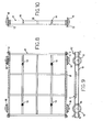
- the production line in Figure 1 for obtaining bitumen cakes includes a plurality of processing stations scattered sequentially along a processing path. More specifically, the production line essentially comprises a bitumen casting station 1, a bitumen cake cooling station2,a cake shake-out station 3, a cake packaging station 4,and a palletizing station 5 for the packaged cakes. All of the processing stations; 1 to 5 operate in a fully automated manner, thepro- duction line being de signed to be controlled by a single operator facing a control console 6. Casting at the station 1 takes place intermittently into four pans or basins 7 at a time ( Figures 1 to 4). The pans 7 are carried in groups of twelve on a pan-carrying or support frame or platform 8 ( Figures 5 to 10), which keeps them divided into three rows of four pans each.
- the pans 7 have a flanged rim 9 which extends continuously along the entire periphery of the respective pan and is radiused at the corners.
- the sidewalls of each pan 7 are flared out to facilitate the removal of the bitumen cakes solidified there in
- the bottom 10 of the pans is spanned by two straight recessed ribs or beads 11 crossing each other to an "X", which have the dual function of ._stiffening and facilitating separation from the bitumen cakes cast and cooled within the pans, as will be explained hereinafter.
- a permanent anti-adhesion inner coating comprising a silicone paint, such as a product available on the market under the trade name of Rhodorsil Silicones and produced by the French firm Rhodorsil, Paris (France).
- the pans 7 may be sprayed internally (at least for a certain number of casts, while the pans are still new and the anti-adhesion coating has yet to "settle") with a non-acidic anti-adhesive or parting agent, such as a suitable soapy emulsion, or a silicone-based product.
- the pans 7 have a horizontal main dimension, in the sense that they are relatively shallow with respect to their length and width dimensions. All this is directed to enable the bitumen, once solidified, to part readily from the pan walls by having a minimum surface area of contact therewith, its top larger area surface being left quite free.
- pans 7 of pressed sheet metal which are carried in groups of 12 on specially provided platform 8, to a total of 338 platforms.
- Most of the platforms are equal in size and construction to the platform shown in Figures 5 to 7, some other platforms being identical to the platform shown in Figures 8 to 10.
- the platform shown in Figures 5 to 7 has a grid structure defining twelve receptacles for accommodating as many pans 7 which, as mentioned, bear on the platform along their flanged rims 9.
- each platform or frame 8 is provided on the bottom side with two pairs of rollers 14 aligned in the platform direction of movement and arranged to roll along rails or runways 15 ( Figures 1,,13 and 14).
- the frames or platforms 8 of Figures 8 to 10 may be, as an example, thirteen in number, and compared to the other platforms, have in addition strengthened oversize side panels and four side-mounted wheels 16 intended for rolling along rails 17 ( Figures 1 and 18).
- Figures 11 and 12 illustrate a pusher assembly 19 located at the shake-out station 3.
- the assembly 19 comprises four pawls 20 mounted in pairs on a rigid support quadrangular structure 21 which is journalled for rotation about a horizontal axis 22.
- Each support structure 21 is provided, in the proximities.of the pawls 20, with a lug 23 extending downwards and having a bore 24.
- the lugs 23 are intended for articulation to one end of a respective actuator jack (not shown), which other end is articulated, through a bracket 25, to the frame of the station 3.
- a platform 8 is being carried to overlie the four pawls 20 such that the latter are located approximately at the middle of the bottom of a respectiverow of four pans 7, it becomes possible to impart a resilient deformation on the pan bottom 10 by operating the actuator jacks of the supporting structures 21.
- the bottom 10 of the pans is progressively urged upwardly by the pawls 20, to forcibly separate a bitumen cake 26 contained in each pan away therefrom, while the pans are being held in position on the platform 8 by detent rollers 27, shown in Figures 13 and 14, which are designed to act on the four corners of each pan 7.
- an extiaction apparatus 30 with a double carriage 31 and 32 which can be displaced vertically on wheels 33 by an upright jack 34, and crosswise on wheels 35 by a horizontal jack 36 ( Figures 13 and 14).
- Extending downwardly from the carriage 3 1 are a set of four suction cups 37, which are preferably spring loaded and are so aligned as to be centered over a row of four cakes 26 lying in as many pans 7.
- the axle of the roller 27 is connected, via a linkage rod 44, to a second end roller 27 depending from the end of an arm 45 journalled at 46 to the stationary structure.
- the levers 40 and 45 form, together with the rod 44, and articulated parallelogram structure that is controlled by the roller 43 which, as the carriage 31 is lowered, will ensure good contact of the side rollers 27 with the edges of the outermost pans 7 in a row on the platform 8.
- the pushers 20 With the carriage 31 lowered, the pushers 20 are first brought into action on the bottoms of the basins or pans 7 in a row located beneath the carriage 31, thereafter the suction cups 37 are connected to a vacuum source (not shown) to take hold of the underlying bitumen cakes 26. Should any one hold be less than positive, e.g. if one suction cup 37 fails to make a vacuum-tight seal with the surface of the respective cake 26, then the whole extraction apparatus will stop (owing to the action of control means not shown) until the leaky condition has been corrected.
- the drive chain 38 for the platforms 8 is run both through the shake-out station 3 and through the casting station 1.
- a row of four cakes 26 is being shaken out, it may be arranged for the casting, at the station 1, of liquid bitumen into four pans 7 placed on a platform 8 which has already moved out of the station 3.
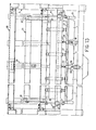
- the casting station 1 incorporates a metering- dispenser device 46 ( Figures 1 and 15 to 17), which comprises a pre-metering vessel 47, which is fed through a limiter valve (not shown) with liquid bitumen from a bitumen source, generally in the form of an insulated line 48 as shown in Figure 1.
- a metering- dispenser device 46 ( Figures 1 and 15 to 17), which comprises a pre-metering vessel 47, which is fed through a limiter valve (not shown) with liquid bitumen from a bitumen source, generally in the form of an insulated line 48 as shown in Figure 1.
- a set of three diaphragms or partitions 49 which are mounted movable in a vertical direction and are spaced apart from one another.
- the partitions can, through a linkage generally indicated at 50 in Figures 15 and 17, be raised and lowered from/into the vessel 47 by means of a jack (not shown).
- the partitions 49 are held in the raised position to favor a complete and even filling of the vessel 47. Thereafter, they are lowered to volumetrically divide the bitumen poured into the vessel 47 into four equal parts.
- the vessel 47 is provided at the top with a fume suction fan 51 and with a loading cell 52.
- the vessel 47 preferably incorporates, on one side thereof, a safety warning mechanism, generally indicated at 53, which has the function of stopping the system in the event of failure to fill or incomplete filling of the vessel 47.
- the vessel 47 is communicated between the partitions 49 to four infusion devices 54 having all the same inside volume and being provided at the bottom with a respective pouring valve 55 and actuator 56.
- Both the infusion devices 54 and vessel 47 are lined with a jacket 56 wherethrough a hot fluid is flown via a piping system 57 to keep the bitumen within the metering dispenser 46 in a liquid state (150-200°C).
- the device 46 is preferably guided vertically by rigid arms 58 mounted cantilever-fashion and having at the top three balls 59.
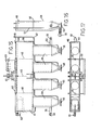
- the appatus 60 comprises two spaced-apart supporting structures 61 and 62, on which a vertical framework 63 is mounted slidably which can reciprocate between the structures 61 and 62.
- a table 64 equipped with two side gripper jaws 65, e.g. of a pneumatically operated type, for gripping the platforms 8.
- the appatus 60 is arranged to sequentially lift the platforms 8 carrying pans 7 filled with bitumen thereon and transport them from the supporting structure 61 to the structure 62, and stack them one on top of the other in stacks or piles 66 containing for instance twenty five platforms each ( Figure 1).
- the arrangement of the platforms 8 is such that at the beginning of each stack there occurs a platform 8 equipped with side-mounted wheels 16 for rolling along the rails 17.
- a stack 66 Once a stack 66 has been completed, it is caused to advance along the rails 17, e.g. by means of a step jack (not shown).
- the rails 17. extend, as an example, through an air cooling tunnel or through a cooling-letting-down area, either in the open air or possibly under forced air circulation, such as by operating one or more blower sets 67.
- the stacking of the platforms 8 is facilitated by the provision of the guides 12 and legs 13 thereon, which also serve as spacer elements between any platform and the one directly underneath.
- the guides 12 and legs 13 thereon which also serve as spacer elements between any platform and the one directly underneath.
- air gaps through which the heat from the bitumen in the pans can be released and, if desired, an airflow may be forced.
- the provision for stacking the platforms 8 not only affords an effective cooling of the bitumen with simple and inexpensive means, but also a considerable reduction, over prior systems, in size and space requirements for the solidification of the bitumen, with attendant self- evident benefits both of a technical and economical nature.
- a second elevator-translator appamtus 68 At the outlet end of the tunnel or cooling area, there is provided a second elevator-translator appamtus 68, wholly similar to the apparatus 60 and, consequently, no further described herein.
- the device 68 is arranged to pick up, one by one, the platforms 8 from the foremost stack and again transport them along the rails 15 for feeding into the shake-out station 3.
- the machine 70 is followed by a kiln 71, wherein the heat shrinkable material is caused to adhere by heat application onto the cakes 26.
- the cakes 26 leave the kiln 71 in a packaged condition and may be passed to a palletizing station 5.
- a system like the one discussed above can afford, for example, a daily output of 100 tonnes of packaged cakes under the supervision of a single operator, who would only interfere in the event of malfunctions, plus one person in charge of the palletizing station.
- the cakes 26 - may have a weight of 25 kg each, and a parallelepipedal shape measuring approximately 600 ⁇ 400 ⁇ 125mm,and be packaged in a thin film of heat shrinkable and extendible polyethylene.
Landscapes
- Chemical & Material Sciences (AREA)
- Engineering & Computer Science (AREA)
- Structural Engineering (AREA)
- Chemical Kinetics & Catalysis (AREA)
- Civil Engineering (AREA)
- General Chemical & Material Sciences (AREA)
- Mechanical Engineering (AREA)
- Materials Engineering (AREA)
- Oil, Petroleum & Natural Gas (AREA)
- Organic Chemistry (AREA)
- Confectionery (AREA)
- Bakery Products And Manufacturing Methods Therefor (AREA)
- Agricultural Chemicals And Associated Chemicals (AREA)
- Working-Up Tar And Pitch (AREA)
Priority Applications (1)
| Application Number | Priority Date | Filing Date | Title |
|---|---|---|---|
| AT83101498T ATE23308T1 (de) | 1982-02-26 | 1983-02-17 | Produktionsanlage fuer asphaltbloecke. |
Applications Claiming Priority (2)
| Application Number | Priority Date | Filing Date | Title |
|---|---|---|---|
| IT8491182 | 1982-02-26 | ||
| IT84911/82A IT1159508B (it) | 1982-02-26 | 1982-02-26 | Impianto per la produzione di bitume in pani |
Publications (2)
| Publication Number | Publication Date |
|---|---|
| EP0088258A1 true EP0088258A1 (de) | 1983-09-14 |
| EP0088258B1 EP0088258B1 (de) | 1986-11-05 |
Family
ID=11325608
Family Applications (1)
| Application Number | Title | Priority Date | Filing Date |
|---|---|---|---|
| EP83101498A Expired EP0088258B1 (de) | 1982-02-26 | 1983-02-17 | Produktionsanlage für Asphaltblöcke |
Country Status (5)
| Country | Link |
|---|---|
| US (1) | US4611978A (de) |
| EP (1) | EP0088258B1 (de) |
| AT (1) | ATE23308T1 (de) |
| DE (1) | DE3367374D1 (de) |
| IT (1) | IT1159508B (de) |
Cited By (5)
| Publication number | Priority date | Publication date | Assignee | Title |
|---|---|---|---|---|
| EP0140687A2 (de) * | 1983-10-28 | 1985-05-08 | Permanite Asphalt Limited | Mastixasphaltherstellung |
| US4623491A (en) * | 1984-06-18 | 1986-11-18 | Hoechst Aktiengesellschaft | Process for the preparation of halogenated aliphatic carboxylic acid fluorides |
| EP0472222A1 (de) * | 1987-12-31 | 1992-02-26 | House Food Industrial Co., Ltd. | Vorrichtung zum Füllen eines Behälters mit einer flüssigen Substanz hoher Viskosität |
| EP0644026A1 (de) * | 1993-09-13 | 1995-03-22 | Inhaco Industrieanlagen GmbH & Co. KG | Verfahren zur Herstellung von Rohlingen für Fahrbahnmarkierungsmaterial und Bitumen sowie Vorrichtung zur Durchführung dieses Verfahrens |
| CN109160016A (zh) * | 2018-10-16 | 2019-01-08 | 杨玲 | 一种三明治自动包装生产方法 |
Families Citing this family (7)
| Publication number | Priority date | Publication date | Assignee | Title |
|---|---|---|---|---|
| US4923712A (en) * | 1988-04-07 | 1990-05-08 | Gaf Building Materials Corporation | Asphaltic flashing stick |
| US8167605B2 (en) * | 2008-06-20 | 2012-05-01 | Oria Collapsibles, Llc | Production assembly and process for mass manufacture of a thermoplastic pallet incorporating a stiffened insert |
| US8522694B2 (en) | 2008-06-20 | 2013-09-03 | Oria Collapsibles, Llc | Structural supporting pallet construction with improved perimeter impact absorbing capabilities |
| US8438981B2 (en) | 2008-06-20 | 2013-05-14 | Oria Collapsibles, Llc | Pallet design with buoyant characteristics |
| US8701569B2 (en) | 2008-06-20 | 2014-04-22 | Oria Collapsibles, Llc | Pallet design with structural reinforcement |
| FR3020064A1 (fr) * | 2014-04-18 | 2015-10-23 | Total Marketing Services | Utilisation d'une composition bitumineuse comme liant de collage |
| CN112378731B (zh) * | 2020-12-10 | 2024-04-09 | 长安大学 | 一种沥青弯曲梁流变试验试件成型仪 |
Citations (3)
| Publication number | Priority date | Publication date | Assignee | Title |
|---|---|---|---|---|
| DE1266931B (de) * | 1966-08-12 | 1968-04-25 | Volkswagenwerk Ag | Vorrichtung fuer die Entnahme von Kernen aus den Formkaesten von Kernschiessmaschinen |
| GB1116493A (en) * | 1965-04-20 | 1968-06-06 | Mineralol U Asphaltwerke Attie | Process and device for the production of stackable bitumen in block form |
| US4137692A (en) * | 1974-02-12 | 1979-02-06 | Giorgio Levy | System for metering and film packaging of bitumen and like materials |
Family Cites Families (14)
| Publication number | Priority date | Publication date | Assignee | Title |
|---|---|---|---|---|
| US1304185A (en) * | 1919-05-20 | ontario | ||
| US1541206A (en) * | 1923-06-05 | 1925-06-09 | Nat Gypsum Products Company | Hollow-tile machine |
| US2261952A (en) * | 1936-09-03 | 1941-11-11 | Servel Inc | Refrigeration |
| US2342743A (en) * | 1942-03-06 | 1944-02-29 | Lutes Herschel | Refrigerating apparatus |
| US2433211A (en) * | 1947-09-05 | 1947-12-23 | Jules P Gits | Ice cube tray |
| US3353236A (en) * | 1963-08-20 | 1967-11-21 | U S Perlite Corp | Apparatus for producing acoustical tile |
| US3348279A (en) * | 1965-10-21 | 1967-10-24 | Flexicore Co | Stripping system for concrete slab casting form |
| US3483908A (en) * | 1968-01-08 | 1969-12-16 | Monsanto Co | Container having discharging means |
| FR1570496A (de) * | 1968-01-30 | 1969-06-13 | ||
| US3648964A (en) * | 1970-02-12 | 1972-03-14 | Eaton Yale & Towne | Ice tray with integral twist restoring element |
| US3867503A (en) * | 1972-03-01 | 1975-02-18 | Flexicore Co | Method of stripping slab casting forms |
| US4035126A (en) * | 1974-03-13 | 1977-07-12 | Manning Target Systems, Inc. | Molding apparatus |
| FR2443324A1 (fr) * | 1978-12-04 | 1980-07-04 | Bertin & Cie | Dispositif permettant le moulage et le demoulage de produits divers |
| FR2469992A1 (fr) * | 1979-11-20 | 1981-05-29 | Barbier Rene | Moule destine a la fabrication de plaques et notamment de plaques en platre |
-
1982
- 1982-02-26 IT IT84911/82A patent/IT1159508B/it active
-
1983
- 1983-02-17 DE DE8383101498T patent/DE3367374D1/de not_active Expired
- 1983-02-17 EP EP83101498A patent/EP0088258B1/de not_active Expired
- 1983-02-17 AT AT83101498T patent/ATE23308T1/de not_active IP Right Cessation
-
1985
- 1985-06-14 US US06/744,863 patent/US4611978A/en not_active Expired - Lifetime
Patent Citations (3)
| Publication number | Priority date | Publication date | Assignee | Title |
|---|---|---|---|---|
| GB1116493A (en) * | 1965-04-20 | 1968-06-06 | Mineralol U Asphaltwerke Attie | Process and device for the production of stackable bitumen in block form |
| DE1266931B (de) * | 1966-08-12 | 1968-04-25 | Volkswagenwerk Ag | Vorrichtung fuer die Entnahme von Kernen aus den Formkaesten von Kernschiessmaschinen |
| US4137692A (en) * | 1974-02-12 | 1979-02-06 | Giorgio Levy | System for metering and film packaging of bitumen and like materials |
Cited By (6)
| Publication number | Priority date | Publication date | Assignee | Title |
|---|---|---|---|---|
| EP0140687A2 (de) * | 1983-10-28 | 1985-05-08 | Permanite Asphalt Limited | Mastixasphaltherstellung |
| EP0140687A3 (de) * | 1983-10-28 | 1987-04-22 | Permanite Asphalt Limited | Mastixasphaltherstellung |
| US4623491A (en) * | 1984-06-18 | 1986-11-18 | Hoechst Aktiengesellschaft | Process for the preparation of halogenated aliphatic carboxylic acid fluorides |
| EP0472222A1 (de) * | 1987-12-31 | 1992-02-26 | House Food Industrial Co., Ltd. | Vorrichtung zum Füllen eines Behälters mit einer flüssigen Substanz hoher Viskosität |
| EP0644026A1 (de) * | 1993-09-13 | 1995-03-22 | Inhaco Industrieanlagen GmbH & Co. KG | Verfahren zur Herstellung von Rohlingen für Fahrbahnmarkierungsmaterial und Bitumen sowie Vorrichtung zur Durchführung dieses Verfahrens |
| CN109160016A (zh) * | 2018-10-16 | 2019-01-08 | 杨玲 | 一种三明治自动包装生产方法 |
Also Published As
| Publication number | Publication date |
|---|---|
| IT1159508B (it) | 1987-02-25 |
| IT8284911A0 (it) | 1982-02-26 |
| DE3367374D1 (en) | 1986-12-11 |
| US4611978A (en) | 1986-09-16 |
| ATE23308T1 (de) | 1986-11-15 |
| EP0088258B1 (de) | 1986-11-05 |
Similar Documents
| Publication | Publication Date | Title |
|---|---|---|
| EP0088258B1 (de) | Produktionsanlage für Asphaltblöcke | |
| US5591463A (en) | Apparatus for the thermoforming and stacking of hollow objects incorporating a base formed from thermoplastics sheet material | |
| EP0139650B1 (de) | Verfahren und vorrichtung zum laden eines lager- oder transportregals | |
| EP3111768B1 (de) | Anlage zur fertigung von nahrungsmitteln | |
| AU586506B2 (en) | Cheese press | |
| CA1037071A (en) | Method and apparatus for forming tyne layers in automatic brick stacking systems | |
| US20070196537A1 (en) | Handling apparatus for handling compacted curd blocks | |
| EP0397279B1 (de) | Vorrichtung zur Herstellung von Bohnenbruch | |
| CA2026062A1 (en) | Process and apparatus for transporting stacks of blanks for producing (cigarette) packs | |
| US3976208A (en) | Apparatus for providing endless succession of compartmented trays | |
| US20220143810A1 (en) | Automated System For Handling Containers With Product Loading | |
| US4137692A (en) | System for metering and film packaging of bitumen and like materials | |
| US4306657A (en) | System for metering and film packaging of bitumen and like materials | |
| US2957287A (en) | Apparatus for depositing filled paper cartons or containers | |
| US2946164A (en) | Method of placing cartons into packing cases | |
| US3653525A (en) | Container unloading and transfering apparatus | |
| US4022334A (en) | Apparatus for stacking sacks onto pallets | |
| JPH0541482B2 (de) | ||
| US6692212B2 (en) | Method for stacking containers comprising thermoplastic, and apparatus for executing the method | |
| US4013183A (en) | Apparatus and method for stacking bricks in preparation for strapping | |
| GB933094A (en) | Pan stacking and unstacking system | |
| US6413568B1 (en) | Method and apparatus for producing cut fresh curd blocks | |
| US3992049A (en) | Apparatus for stacking bricks in preparation for strapping | |
| US4752174A (en) | Auto stacker | |
| US3243076A (en) | Method and apparatus for denesting articles |
Legal Events
| Date | Code | Title | Description |
|---|---|---|---|
| PUAI | Public reference made under article 153(3) epc to a published international application that has entered the european phase |
Free format text: ORIGINAL CODE: 0009012 |
|
| AK | Designated contracting states |
Designated state(s): AT BE CH DE FR GB LI LU NL SE |
|
| 17P | Request for examination filed |
Effective date: 19840308 |
|
| GRAA | (expected) grant |
Free format text: ORIGINAL CODE: 0009210 |
|
| AK | Designated contracting states |
Kind code of ref document: B1 Designated state(s): AT BE CH DE FR GB LI LU NL SE |
|
| PG25 | Lapsed in a contracting state [announced via postgrant information from national office to epo] |
Ref country code: NL Effective date: 19861105 Ref country code: LI Effective date: 19861105 Ref country code: CH Effective date: 19861105 Ref country code: BE Effective date: 19861105 Ref country code: AT Effective date: 19861105 |
|
| REF | Corresponds to: |
Ref document number: 23308 Country of ref document: AT Date of ref document: 19861115 Kind code of ref document: T |
|
| PG25 | Lapsed in a contracting state [announced via postgrant information from national office to epo] |
Ref country code: SE Effective date: 19861130 |
|
| ET | Fr: translation filed | ||
| REF | Corresponds to: |
Ref document number: 3367374 Country of ref document: DE Date of ref document: 19861211 |
|
| REG | Reference to a national code |
Ref country code: CH Ref legal event code: PL |
|
| PG25 | Lapsed in a contracting state [announced via postgrant information from national office to epo] |
Ref country code: LU Free format text: LAPSE BECAUSE OF NON-PAYMENT OF DUE FEES Effective date: 19870228 |
|
| NLV1 | Nl: lapsed or annulled due to failure to fulfill the requirements of art. 29p and 29m of the patents act | ||
| PLBE | No opposition filed within time limit |
Free format text: ORIGINAL CODE: 0009261 |
|
| STAA | Information on the status of an ep patent application or granted ep patent |
Free format text: STATUS: NO OPPOSITION FILED WITHIN TIME LIMIT |
|
| 26N | No opposition filed | ||
| PGFP | Annual fee paid to national office [announced via postgrant information from national office to epo] |
Ref country code: GB Payment date: 19960208 Year of fee payment: 14 |
|
| PGFP | Annual fee paid to national office [announced via postgrant information from national office to epo] |
Ref country code: DE Payment date: 19960222 Year of fee payment: 14 |
|
| PGFP | Annual fee paid to national office [announced via postgrant information from national office to epo] |
Ref country code: FR Payment date: 19960228 Year of fee payment: 14 |
|
| PG25 | Lapsed in a contracting state [announced via postgrant information from national office to epo] |
Ref country code: GB Effective date: 19970217 |
|
| GBPC | Gb: european patent ceased through non-payment of renewal fee |
Effective date: 19970217 |
|
| PG25 | Lapsed in a contracting state [announced via postgrant information from national office to epo] |
Ref country code: FR Effective date: 19971030 |
|
| PG25 | Lapsed in a contracting state [announced via postgrant information from national office to epo] |
Ref country code: DE Effective date: 19971101 |
|
| REG | Reference to a national code |
Ref country code: FR Ref legal event code: ST |