EP0087992B1 - Videofrequenz Bildsensorgerät mit automatischer Empfindlichkeitskorrektur für Gebrauch in einem automatischen Fernsehfolgesystem - Google Patents
Videofrequenz Bildsensorgerät mit automatischer Empfindlichkeitskorrektur für Gebrauch in einem automatischen Fernsehfolgesystem Download PDFInfo
- Publication number
- EP0087992B1 EP0087992B1 EP83400273A EP83400273A EP0087992B1 EP 0087992 B1 EP0087992 B1 EP 0087992B1 EP 83400273 A EP83400273 A EP 83400273A EP 83400273 A EP83400273 A EP 83400273A EP 0087992 B1 EP0087992 B1 EP 0087992B1
- Authority
- EP
- European Patent Office
- Prior art keywords
- cell
- optical
- detector
- radiation
- deposit
- Prior art date
- Legal status (The legal status is an assumption and is not a legal conclusion. Google has not performed a legal analysis and makes no representation as to the accuracy of the status listed.)
- Expired
Links
- 230000035945 sensitivity Effects 0.000 title description 6
- 230000003287 optical effect Effects 0.000 claims description 33
- 230000005855 radiation Effects 0.000 claims description 27
- 230000005540 biological transmission Effects 0.000 claims description 19
- 239000003792 electrolyte Substances 0.000 claims description 16
- 238000005286 illumination Methods 0.000 claims description 8
- 230000003071 parasitic effect Effects 0.000 claims description 8
- 238000004090 dissolution Methods 0.000 claims description 3
- 238000003487 electrochemical reaction Methods 0.000 claims description 3
- 230000008021 deposition Effects 0.000 claims description 2
- 238000001514 detection method Methods 0.000 claims description 2
- 230000000903 blocking effect Effects 0.000 claims 2
- 150000001455 metallic ions Chemical class 0.000 claims 1
- 229910052751 metal Inorganic materials 0.000 description 14
- 239000002184 metal Substances 0.000 description 14
- 238000010586 diagram Methods 0.000 description 9
- 230000006870 function Effects 0.000 description 8
- 230000002745 absorbent Effects 0.000 description 5
- 239000002250 absorbent Substances 0.000 description 5
- 229910021645 metal ion Inorganic materials 0.000 description 3
- 239000007787 solid Substances 0.000 description 3
- 239000000725 suspension Substances 0.000 description 3
- XUIMIQQOPSSXEZ-UHFFFAOYSA-N Silicon Chemical compound [Si] XUIMIQQOPSSXEZ-UHFFFAOYSA-N 0.000 description 2
- 230000009471 action Effects 0.000 description 2
- 230000004907 flux Effects 0.000 description 2
- 230000004044 response Effects 0.000 description 2
- 229910052710 silicon Inorganic materials 0.000 description 2
- 239000010703 silicon Substances 0.000 description 2
- 230000005679 Peltier effect Effects 0.000 description 1
- ATJFFYVFTNAWJD-UHFFFAOYSA-N Tin Chemical compound [Sn] ATJFFYVFTNAWJD-UHFFFAOYSA-N 0.000 description 1
- 241000219422 Urtica Species 0.000 description 1
- 235000009108 Urtica dioica Nutrition 0.000 description 1
- 238000010521 absorption reaction Methods 0.000 description 1
- 230000000712 assembly Effects 0.000 description 1
- 238000000429 assembly Methods 0.000 description 1
- 230000001276 controlling effect Effects 0.000 description 1
- 238000001816 cooling Methods 0.000 description 1
- 238000009792 diffusion process Methods 0.000 description 1
- 230000000694 effects Effects 0.000 description 1
- 229910003437 indium oxide Inorganic materials 0.000 description 1
- PJXISJQVUVHSOJ-UHFFFAOYSA-N indium(iii) oxide Chemical compound [O-2].[O-2].[O-2].[In+3].[In+3] PJXISJQVUVHSOJ-UHFFFAOYSA-N 0.000 description 1
- 230000010354 integration Effects 0.000 description 1
- 150000002500 ions Chemical class 0.000 description 1
- 230000005291 magnetic effect Effects 0.000 description 1
- 238000004519 manufacturing process Methods 0.000 description 1
- 230000001105 regulatory effect Effects 0.000 description 1
- 229920006395 saturated elastomer Polymers 0.000 description 1
- 229910052709 silver Inorganic materials 0.000 description 1
- 239000004332 silver Substances 0.000 description 1
- 230000003068 static effect Effects 0.000 description 1
- 229910001887 tin oxide Inorganic materials 0.000 description 1
- 238000004804 winding Methods 0.000 description 1
Images



Classifications
-
- G—PHYSICS
- G02—OPTICS
- G02F—OPTICAL DEVICES OR ARRANGEMENTS FOR THE CONTROL OF LIGHT BY MODIFICATION OF THE OPTICAL PROPERTIES OF THE MEDIA OF THE ELEMENTS INVOLVED THEREIN; NON-LINEAR OPTICS; FREQUENCY-CHANGING OF LIGHT; OPTICAL LOGIC ELEMENTS; OPTICAL ANALOGUE/DIGITAL CONVERTERS
- G02F1/00—Devices or arrangements for the control of the intensity, colour, phase, polarisation or direction of light arriving from an independent light source, e.g. switching, gating or modulating; Non-linear optics
- G02F1/01—Devices or arrangements for the control of the intensity, colour, phase, polarisation or direction of light arriving from an independent light source, e.g. switching, gating or modulating; Non-linear optics for the control of the intensity, phase, polarisation or colour
- G02F1/15—Devices or arrangements for the control of the intensity, colour, phase, polarisation or direction of light arriving from an independent light source, e.g. switching, gating or modulating; Non-linear optics for the control of the intensity, phase, polarisation or colour based on an electrochromic effect
- G02F1/1506—Devices or arrangements for the control of the intensity, colour, phase, polarisation or direction of light arriving from an independent light source, e.g. switching, gating or modulating; Non-linear optics for the control of the intensity, phase, polarisation or colour based on an electrochromic effect caused by electrodeposition, e.g. electrolytic deposition of an inorganic material on or close to an electrode
-
- H—ELECTRICITY
- H04—ELECTRIC COMMUNICATION TECHNIQUE
- H04N—PICTORIAL COMMUNICATION, e.g. TELEVISION
- H04N23/00—Cameras or camera modules comprising electronic image sensors; Control thereof
- H04N23/50—Constructional details
- H04N23/54—Mounting of pick-up tubes, electronic image sensors, deviation or focusing coils
-
- H—ELECTRICITY
- H04—ELECTRIC COMMUNICATION TECHNIQUE
- H04N—PICTORIAL COMMUNICATION, e.g. TELEVISION
- H04N23/00—Cameras or camera modules comprising electronic image sensors; Control thereof
- H04N23/70—Circuitry for compensating brightness variation in the scene
- H04N23/75—Circuitry for compensating brightness variation in the scene by influencing optical camera components
Definitions
- the present invention relates to arrangements for video frequency image detecting apparatuses in which the image of the observed scene is formed by receiving optics on the photosensitive surface of a detector device and which include means for automatically correcting the sensitivity.
- the invention is intended for such devices where the detector device is constituted by a solid circuit of the charge transfer device type (DTC for short), or even by a shooting tube whose target is based on silicon.
- DTC charge transfer device type
- detectors have a major drawback; their sensitivity remains constant but within a far too limited range.
- the useful dynamic range should vary from 1 to 1000.
- a silicon sensor has a useful dynamic range of the order of 1 to 10, or approximately 20 dB where the response is linear with an exploitable signal-to-noise ratio. Then, for any greater illumination, the detector device becomes saturated. Furthermore, it is not possible to remedy this state of affairs directly by the action of an electronic control at the level of the detector itself.
- Another solution is to use a padded diaphragm controlled by the servo loop.
- An assembly of this kind is described in French patent No. 2446468.
- the diaphragm is rotated around the optical axis to move the blades under the action of centrifugal force.
- the rotation speed is controlled by a loop to regulate the average video level.
- the device stabilizes the average light flux detected by the DTC sensor.
- An object of the present invention is to remedy these various drawbacks by using as variable optical attenuator for automatically correcting the sensitivity of the device, a cell to the electrolyte, the principle of which is well known for display.
- the attenuator is thus constituted by a static means, of small bulk and weight, which has undeniable advantages when it is desired to incorporate it in a gyrostabilized version.
- a video frequency image detecting apparatus comprising receiving optics for forming the image of the scene observed on the photosensitive plane of an image detector, and means for variable optical attenuation. electronically controlled connected by a servo loop to the video output to regulate the video signal according to the lighting of the scene and increase the operating dynamics of the device, characterized in that the optical attenuation means are formed by the interposition on the optical path of at least one cell with an electrolyte containing metal ions, the electrolyte being interposed between two walls coated with electrodes connected to electrical supply means to produce by electrochemical reaction, the deposit or the dissolution according to the direction of the supply current, of a metal layer whose optical properties of reflection and transmission vary in f anointing of the thickness of the deposit, these optical properties being used to produce said variable attenuation, the power supply means being constituted by said control loop, and in that the receiving optics (1), the means of optical attenuation (4) and the detector (2) are supported by a gy
- the videofrequency image detecting device comprises a receiving optic 1 symbolized by a lens, and a detector device 2.
- the Z axis represents the optical axis, or viewing axis of the device, which ends at the center of the photosensitive surface 20 of the detector.
- the optic 1 forms the image of the field observed at the photosensitive surface 20. Most often the aiming is carried out at infinity and the surface 20 is located in the focal plane.
- the detector 2 can consist of a solid DTC detector at 21 composed of the detector elements and of the preamplification integrated circuits, and of a cooling device 22, for example a cryostat with Peltier effect or the like.
- the assembly also includes a loop 3 intended to control the video signal as a function of the fluctuations in brightness of the scene observed in order to operate in a large light range and to give the device great dynamics.
- This loop acts on one of the optical attenuation means 4 which comprises at least one electrolyte cell.
- the loop provides controlled continuous power to the cell to vary its optical properties of transparency or reflection, as appropriate.
- Element 5 symbolizes the support structure of the assembly and in particular of the optical-attenuator and detector assembly.
- the attenuator is advantageously placed on the optical path between the receiving optics 1 and the photosensitive surface so that it can be produced in small dimensions.
- the structure of an electrolyte cell will now be recalled using FIG. 2 or fig. 3.
- the cell therefore consists of an electrolyte 10 containing metal ions, inserted between a first wall 11 coated with a first transparent conductive layer 12 forming an electrode and a second wall 13 coated with a second conductive layer 14 forming a counter-electrode .
- DC power supply means are connected to the terminals of the electrodes 12 and 14 to cause the deposition or dissolution, by electrochemical reaction from the ions, of a metal layer 15 on the transparent electrode 12.
- the known structure also comprises insulating deposits on the remaining areas of the transparent electrode 12; an electrolytic display device of this kind is described in particular in French patent No. 2352361.
- the metal ions for example silver, contained in the electrolyte will deposit on the transparent electrode 12 which can be based on tin or indium oxide.
- the metal layer 15 dissolves and the metal is deposited on the counter-electrode 14.
- the version fig. 2 relates to use by transmission.
- the counter-electrode 14 was first of all given an annular shape so as to allow almost all of the transparent wall 13 to pass through the incident light flux of which a radius RI is shown.
- the second wall 11 is also transparent.
- the radius RI will cross the cettute and will give the useful radius RU at the output by transmission.
- Part of the light energy is lost by absorption and reflection during the passage of the device, in particular the RP radiation reflected by the metal deposit 15.
- the cell is used by reflection; the incident radiation RI is reflected by the metal deposit 15 to provide the useful radiation RU while part of this radiation passes through this deposit 15 of small thickness, it is the radiation RP which goes towards the bottom of the cell.
- the wall 11 is transparent and the wall 13 is preferably opaque.
- the thickness of the layer 15 varies the proportion RP of the incident radiation RI which passes through this layer and therefore correlatively the proportion of the useful radiation RU reflected in> nettle towards the detector.
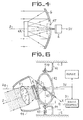
- Fig. 4 shows, according to a partial diagram, an embodiment in which the cell is used for reflection. It is a device which includes a Cassegrain type receiving optic with a main mirror 6, the secondary mirror being formed by means of the cell 4R used in reflection (FIG. 3).
- the control loop 3 which provides electrical control of the cell tank 4, may include the elements shown in FIG. 1.
- the video signal SV from the detector device 2 is first applied to a filter 31 intended to suppress high frequency noise.
- This filter is followed by an integrator circuit or a peak detector circuit 32.
- the filter 31 is of the low-pass type and the circuit makes it possible to regulate the illumination at the input of the detector in function of the average illumination in the image.
- the integrator has a time constant that covers one or more frames.
- the filter is of the bandpass type and the illumination of the detector is regulated as a function of the peak level of that of the scene.
- the signal thus processed is applied to a differential comparator 33 where it is compared to a threshold voltage or reference voltage VS which corresponds to a determined level of illumination (medium or peak) which it is desired to obtain for the device.
- the error signal S2 at the output of comparator 33 is amplified by an amplifier 35 which supplies the cell with a direct current 1 proportional to the error S2, in amplitude and in sign.
- a correction network 34 is interposed between the output S2 of the comparator 33 and the amplifier 35 to ensure the stability of the loop by compensating for the integrating effect of the cell and by correcting the non-linearities of the cell transfer function.
- This network can be of the phase advance type for example.
- the correction network is determined to compensate for these non-linearities.
- the electrical control of the tank intended to regulate the level of illumination on the sensitive face 20 of the detector can be carried out using a circuit similar to that of the fig. 1.
- the first is that the direction of the tank control current must be reversed because the more the current flows the less the device attenuates, the second is that the correction law for linearizing the loop gain is no longer the same.
- Fig. 5 shows an alternative embodiment of a cell operating by transmission described with the aid of FIG. 2.
- This variant effectively amounts to constituting two cells forming a variable transparency attenuator.
- the structure is symmetrical with respect to the annular counter-electrode 14 with two electrodes 12A and 12B on which the corresponding metal deposits 15A and 15B are formed or dissolve depending on the direction of the supply current.
- Each of these deposits contributes to a reflection rate of the incident radiation RI.
- the two reflections RPA and RPB act to vary the rate of the light energy transmitted, this rate obviously being a function of the thickness of the metal deposits 15A and 15B.
- Fig. 6 is a simplified diagram of a video frequency image detection device according to the invention mounted according to a use more particularly envisaged on a gyrostabilized suspension.
- the receiving optical system 1, the detector device 2 and the variable attenuating device 4 are suspended from the gimbal according to a free gyroscope assembly shown with an external router.
- the suspension with two degrees of freedom is identifiable by a first frame 41 secured to the frame or external body 5, a central part 42 shown in the form of a ring and which can rotate around the reference axis YO and a second frame 43 which can rotate around an X axis perpendicular to YO and the optical Z axis or gyroscope axis.
- the router 44 or gyroscopic mass is rotated around the Z axis and the gyroscopic assembly stabilizes this direction in space when the reference axis ZO linked to the bearing structure, such as the longitudinal axis of a missile, deviates from direction Z.
- the router has a rotor 44 and stator windings 45 supplied from a circuit not shown.
- Block 3 constitutes the video level control loop (medium or peak) by controlling the continuous supply of the electrolyte cell 4.
- the optical reception system is preferably a catadioptric system of the Cassegrain type already mentioned and which can be fitted out according to the diagram in fig. 7 with a variable transparency attenuator or according to the diagram in FIG. 8 with a variable reflection attenuator.
- the gyroscope is represented with its Z axis coinciding with the reference position ZO corresponding to the longitudinal axis of the missile, that is to say ie for a zero deflection angle between these two axes; the aforementioned Z axis is perpendicular to the plane of the figure.
- the Cassegrain optics comprises the main mirror 6 and the secondary mirror 7.
- a corrective optic 8 which precedes the variable transparency attenuating cell 4T itself placed in front of the detector 2.
- the detector is cooled.
- the router 44 comprises an annular magnet 50 which undergoes the magnetic effects generated by the coils 45 called precession coils which are fixedly mounted on a mechanical support 51 secured to the body 5 of the missile.
- the router 44 is decoupled from the frame 43 supporting the optical, attenuator and detector assembly by ball bearings 52.
- the secondary mirror 7 is supported by arms 53 and a conical cover 54.
- the shaft 41 is hollow to allow passage to the various connection wires leading, on the one hand, to the detector and, on the other hand, to the cell 4T, these wires being connected downstream to the corresponding electronic circuits.
- These connections include in particular the video output SV and the supply of the cell 4T from loop 3; the other connections are those intended for the exploitation of the video signal SV and various connections (power supply continuous connections, synchronizations) necessary for the solid-state detector circuit 21.
- FIG. 8 In the television seeker assembly of FIG. 8 we find the same structure with the difference that the cell is used as a 4R reflection attenuator and that one of its surfaces plays the role of the secondary mirror of Cassegrain optics.
- An embodiment of the cell is shown in more detail in FIG. 9 with indication of the optical rays to explain its operation.
- the useful radiation intended for the detector is shown in solid lines, and the non-useful radiation is dotted.
- the transparent inlet wall 11 acts as a secondary mirror on its internal surface when this face is made reflective by the metal deposit 15.
- the strip 11 with the transparent electrode 12 and the metal deposit 15 constitute a Mangin mirror, the face external is flat and the internal face is curved, so that the reflection on the deposit 15 returns radiation towards the axis Z.
- the input blade has a number of characteristics. Its external face is treated with anti-reflections. Its thickness is determined sufficient for the residual stray image to be focused as far as possible from the useful focal plane.
- the shape of the outer diopter, a plane in the figure, is such that the first stray image formed by reflection on the diopter is at a finite distance in an area where it is possible to stop it by a simple diaphragm.
- This last condition is easily achieved in the case of Cassegrain optics since the useful radiation reflected by the two mirrors is between two cones centered on the optical axis Z and the internal part of the first cone is not used for operation and can therefore include the diaphragm in question referenced 60.
- This diaphragm does not disturb the transmission of useful radiation to the detector. It can be obtained as shown in fig. 8 by a deposit opaque to the expected radiation and which is carried out on a diopter of a first corrective lens 8a.
- the free gyroscopic device does not necessarily imply a suspension with the outer router, mounting with the inner router is also possible.
- the advantages provided by an apparatus in accordance with the invention, in particular in the use of television seeker are essentially: a large attenuation dynamic easily covering the range 1 to 1000 for the attenuator-detector assembly; there is no moving mechanical part, the masses of metal displaced being very small (thickness of the metal deposit of the order of a few hundredths of an Angstrom) which does not risk unbalancing the gyroscope; the response speed reaches at least that of mechanical diaphragm devices and is sufficient for the seeker application, production is carried out in low volume; the cost is low as well as the power consumption.
Landscapes
- Physics & Mathematics (AREA)
- Engineering & Computer Science (AREA)
- Multimedia (AREA)
- Signal Processing (AREA)
- Nonlinear Science (AREA)
- Chemical & Material Sciences (AREA)
- Inorganic Chemistry (AREA)
- General Physics & Mathematics (AREA)
- Optics & Photonics (AREA)
- Photometry And Measurement Of Optical Pulse Characteristics (AREA)
Claims (9)
Applications Claiming Priority (2)
| Application Number | Priority Date | Filing Date | Title |
|---|---|---|---|
| FR8202953 | 1982-02-23 | ||
| FR8202953A FR2522231B1 (fr) | 1982-02-23 | 1982-02-23 | Appareil detecteur d'images videofrequence a correction automatique de sensibilite, utilisable sur un autodirecteur television |
Publications (2)
| Publication Number | Publication Date |
|---|---|
| EP0087992A1 EP0087992A1 (de) | 1983-09-07 |
| EP0087992B1 true EP0087992B1 (de) | 1985-10-16 |
Family
ID=9271254
Family Applications (1)
| Application Number | Title | Priority Date | Filing Date |
|---|---|---|---|
| EP83400273A Expired EP0087992B1 (de) | 1982-02-23 | 1983-02-08 | Videofrequenz Bildsensorgerät mit automatischer Empfindlichkeitskorrektur für Gebrauch in einem automatischen Fernsehfolgesystem |
Country Status (3)
| Country | Link |
|---|---|
| EP (1) | EP0087992B1 (de) |
| DE (1) | DE3361004D1 (de) |
| FR (1) | FR2522231B1 (de) |
Cited By (1)
| Publication number | Priority date | Publication date | Assignee | Title |
|---|---|---|---|---|
| US7567291B2 (en) | 1997-12-31 | 2009-07-28 | Gentex Corporation | Vehicle vision system |
Families Citing this family (3)
| Publication number | Priority date | Publication date | Assignee | Title |
|---|---|---|---|---|
| DE3418394C2 (de) * | 1984-05-17 | 1986-07-17 | Messerschmitt-Bölkow-Blohm GmbH, 8012 Ottobrunn | Bildaufnahme- und Bildverarbeitungsverfahren sowie -vorrichtungen für in Fluggeräten mitgeführte Videokameras |
| FR2629298A1 (fr) * | 1988-03-25 | 1989-09-29 | Cornuejols Georges | Dispositif de prise d'images comportant un moyen d'addition de lumiere |
| US6008486A (en) * | 1997-12-31 | 1999-12-28 | Gentex Corporation | Wide dynamic range optical sensor |
Family Cites Families (4)
| Publication number | Priority date | Publication date | Assignee | Title |
|---|---|---|---|---|
| DE1155538B (de) * | 1958-02-03 | 1963-10-10 | Eastman Kodak Co | Verfahren zum Regeln der Lichtintensitaet und hierzu dienendes Filter |
| US3630603A (en) * | 1966-02-07 | 1971-12-28 | Eugene C Letter | Light-control device and spectacles using reversible oxidation reduction reactions in a material containing lead fluoride |
| US3576393A (en) * | 1967-12-15 | 1971-04-27 | Us Navy | Automatic exposure control for a slow scan vidicon |
| FR2473237A1 (fr) * | 1980-01-04 | 1981-07-10 | Thomson Csf | Dispositif photodetecteur generateur d'images video, et systeme comportant un tel dispositif |
-
1982
- 1982-02-23 FR FR8202953A patent/FR2522231B1/fr not_active Expired
-
1983
- 1983-02-08 EP EP83400273A patent/EP0087992B1/de not_active Expired
- 1983-02-08 DE DE8383400273T patent/DE3361004D1/de not_active Expired
Cited By (1)
| Publication number | Priority date | Publication date | Assignee | Title |
|---|---|---|---|---|
| US7567291B2 (en) | 1997-12-31 | 2009-07-28 | Gentex Corporation | Vehicle vision system |
Also Published As
| Publication number | Publication date |
|---|---|
| FR2522231B1 (fr) | 1986-01-31 |
| FR2522231A1 (fr) | 1983-08-26 |
| EP0087992A1 (de) | 1983-09-07 |
| DE3361004D1 (en) | 1985-11-21 |
Similar Documents
| Publication | Publication Date | Title |
|---|---|---|
| EP0044791B1 (de) | Einrichtung zum Detektieren von Infrarotstrahlung | |
| EP0032334B1 (de) | Photodetektorvorrichtung zur Erzeugung von Videobildern mit automatischer Empfindlichkeitsregelung | |
| EP0004227A1 (de) | Einrichtung zur optoelektrischen Detektion und zur Bestimmung der Winkelablage eines leuchtenden Objekts, sowie deren Verwendung | |
| EP1449020B1 (de) | Einrichtung zur schnellen sektoriellen oder panoramischen überwachung ohne anscheinende bewegung | |
| EP2248338A1 (de) | Optische mischvorrichtung für multifokale abbildung und ir-kalibrierung | |
| EP0674775B1 (de) | Teleskop zu abbildungszwecken im infrarot oder sichtbarem spektrum | |
| EP0087992A1 (de) | Videofrequenz Bildsensorgerät mit automatischer Empfindlichkeitskorrektur für Gebrauch in einem automatischen Fernsehfolgesystem | |
| EP0104960B1 (de) | Bifokales optisches System und seine Anwendung in einem Video-Bilddetektorgerät | |
| FR2726080A1 (fr) | Capteur optoelectronique pour mesurer l'intensite et la direction d'incidence d'un faisceau lumineux | |
| FR2532441A1 (fr) | Appareil pour la vision diurne et nocturne | |
| EP0130869A1 (de) | Video-Abbildungsgerät, insbesondere für sich selbst lenkende Körper | |
| EP4291937B1 (de) | Beobachtungssystem und -verfahren | |
| EP0099769B1 (de) | Vorrichtung zur Analyse eines räumlichen Feldes zur Winkelortung eines strahlenden Objektes | |
| WO2025120261A1 (fr) | Tube intensificateur d'images et dispositif de vision nocturne associe | |
| EP2388646B1 (de) | Verfahren zur Bilderfassung | |
| WO2022171674A1 (fr) | Système et procédé d'observation | |
| EP0713119A1 (de) | Statisches weitwinkliges Infrarot-Überwachungsgerät mit Mehrfach-Detektorketten | |
| EP0493170B1 (de) | Infrarotsensor mit hoher Erkennungsfähigkeit und Wärmebildkamera mit einem solchen Detektor | |
| FR3015056A1 (fr) | Systeme optique d'observation spatiale a balayage | |
| EP0593327A1 (de) | Infrarotkamera mit Schutz vor parasitären Intensitätsmodulationen des detektierten Lichtstroms | |
| FR2506329A1 (fr) | Procede de determination par voie optique du profil des charges dans le gueulard d'un haut fourneau | |
| FR2676823A1 (fr) | Dispositif de mesure de l'ecart d'un projectile. | |
| FR2851054A1 (fr) | Telescope optique de grand champ et en particulier pour l'observation astronomique a partir d'un satellite | |
| FR2805352A1 (fr) | Dispositif de desensibilisation d'un systeme d'imagerie a des objets lumineux perturbateurs | |
| EP0635704B1 (de) | Trennscharfer UV-Weitwinkelempfänger |
Legal Events
| Date | Code | Title | Description |
|---|---|---|---|
| PUAI | Public reference made under article 153(3) epc to a published international application that has entered the european phase |
Free format text: ORIGINAL CODE: 0009012 |
|
| AK | Designated contracting states |
Designated state(s): DE GB IT NL SE |
|
| 17P | Request for examination filed |
Effective date: 19840120 |
|
| ITF | It: translation for a ep patent filed | ||
| RBV | Designated contracting states (corrected) |
Designated state(s): DE GB IT SE |
|
| GRAA | (expected) grant |
Free format text: ORIGINAL CODE: 0009210 |
|
| AK | Designated contracting states |
Designated state(s): DE GB IT SE |
|
| REF | Corresponds to: |
Ref document number: 3361004 Country of ref document: DE Date of ref document: 19851121 |
|
| PLBE | No opposition filed within time limit |
Free format text: ORIGINAL CODE: 0009261 |
|
| STAA | Information on the status of an ep patent application or granted ep patent |
Free format text: STATUS: NO OPPOSITION FILED WITHIN TIME LIMIT |
|
| 26N | No opposition filed | ||
| PG25 | Lapsed in a contracting state [announced via postgrant information from national office to epo] |
Ref country code: SE Effective date: 19870209 |
|
| GBPC | Gb: european patent ceased through non-payment of renewal fee | ||
| PG25 | Lapsed in a contracting state [announced via postgrant information from national office to epo] |
Ref country code: DE Effective date: 19871103 |
|
| PG25 | Lapsed in a contracting state [announced via postgrant information from national office to epo] |
Ref country code: GB Effective date: 19881122 |
|
| EUG | Se: european patent has lapsed |
Ref document number: 83400273.5 Effective date: 19880215 |