EP0087203A2 - Low-weight agricultural tractor with removable implement coupling and ballasting means - Google Patents
Low-weight agricultural tractor with removable implement coupling and ballasting means Download PDFInfo
- Publication number
- EP0087203A2 EP0087203A2 EP83200251A EP83200251A EP0087203A2 EP 0087203 A2 EP0087203 A2 EP 0087203A2 EP 83200251 A EP83200251 A EP 83200251A EP 83200251 A EP83200251 A EP 83200251A EP 0087203 A2 EP0087203 A2 EP 0087203A2
- Authority
- EP
- European Patent Office
- Prior art keywords
- tractor
- lifting device
- ballast weight
- hitching member
- anyone
- Prior art date
- Legal status (The legal status is an assumption and is not a legal conclusion. Google has not performed a legal analysis and makes no representation as to the accuracy of the status listed.)
- Withdrawn
Links
Images

Classifications
-
- B—PERFORMING OPERATIONS; TRANSPORTING
- B62—LAND VEHICLES FOR TRAVELLING OTHERWISE THAN ON RAILS
- B62D—MOTOR VEHICLES; TRAILERS
- B62D49/00—Tractors
- B62D49/002—Tractors characterised by being of the low ground pressure type
-
- B—PERFORMING OPERATIONS; TRANSPORTING
- B60—VEHICLES IN GENERAL
- B60K—ARRANGEMENT OR MOUNTING OF PROPULSION UNITS OR OF TRANSMISSIONS IN VEHICLES; ARRANGEMENT OR MOUNTING OF PLURAL DIVERSE PRIME-MOVERS IN VEHICLES; AUXILIARY DRIVES FOR VEHICLES; INSTRUMENTATION OR DASHBOARDS FOR VEHICLES; ARRANGEMENTS IN CONNECTION WITH COOLING, AIR INTAKE, GAS EXHAUST OR FUEL SUPPLY OF PROPULSION UNITS IN VEHICLES
- B60K17/00—Arrangement or mounting of transmissions in vehicles
- B60K17/28—Arrangement or mounting of transmissions in vehicles characterised by arrangement, location, or type of power take-off
-
- B—PERFORMING OPERATIONS; TRANSPORTING
- B60—VEHICLES IN GENERAL
- B60K—ARRANGEMENT OR MOUNTING OF PROPULSION UNITS OR OF TRANSMISSIONS IN VEHICLES; ARRANGEMENT OR MOUNTING OF PLURAL DIVERSE PRIME-MOVERS IN VEHICLES; AUXILIARY DRIVES FOR VEHICLES; INSTRUMENTATION OR DASHBOARDS FOR VEHICLES; ARRANGEMENTS IN CONNECTION WITH COOLING, AIR INTAKE, GAS EXHAUST OR FUEL SUPPLY OF PROPULSION UNITS IN VEHICLES
- B60K17/00—Arrangement or mounting of transmissions in vehicles
- B60K17/34—Arrangement or mounting of transmissions in vehicles for driving both front and rear wheels, e.g. four wheel drive vehicles
- B60K17/356—Arrangement or mounting of transmissions in vehicles for driving both front and rear wheels, e.g. four wheel drive vehicles having fluid or electric motor, for driving one or more wheels
-
- B—PERFORMING OPERATIONS; TRANSPORTING
- B62—LAND VEHICLES FOR TRAVELLING OTHERWISE THAN ON RAILS
- B62D—MOTOR VEHICLES; TRAILERS
- B62D49/00—Tractors
- B62D49/02—Tractors modified to take lifting devices
-
- B—PERFORMING OPERATIONS; TRANSPORTING
- B62—LAND VEHICLES FOR TRAVELLING OTHERWISE THAN ON RAILS
- B62D—MOTOR VEHICLES; TRAILERS
- B62D49/00—Tractors
- B62D49/06—Tractors adapted for multi-purpose use
-
- B—PERFORMING OPERATIONS; TRANSPORTING
- B62—LAND VEHICLES FOR TRAVELLING OTHERWISE THAN ON RAILS
- B62D—MOTOR VEHICLES; TRAILERS
- B62D49/00—Tractors
- B62D49/06—Tractors adapted for multi-purpose use
- B62D49/0621—Tractors adapted for multi-purpose use comprising traction increasing arrangements, e.g. all-wheel traction devices, multiple-axle traction arrangements, auxiliary traction increasing devices
-
- B—PERFORMING OPERATIONS; TRANSPORTING
- B62—LAND VEHICLES FOR TRAVELLING OTHERWISE THAN ON RAILS
- B62D—MOTOR VEHICLES; TRAILERS
- B62D61/00—Motor vehicles or trailers, characterised by the arrangement or number of wheels, not otherwise provided for, e.g. four wheels in diamond pattern
- B62D61/10—Motor vehicles or trailers, characterised by the arrangement or number of wheels, not otherwise provided for, e.g. four wheels in diamond pattern with more than four wheels
-
- Y—GENERAL TAGGING OF NEW TECHNOLOGICAL DEVELOPMENTS; GENERAL TAGGING OF CROSS-SECTIONAL TECHNOLOGIES SPANNING OVER SEVERAL SECTIONS OF THE IPC; TECHNICAL SUBJECTS COVERED BY FORMER USPC CROSS-REFERENCE ART COLLECTIONS [XRACs] AND DIGESTS
- Y10—TECHNICAL SUBJECTS COVERED BY FORMER USPC
- Y10S—TECHNICAL SUBJECTS COVERED BY FORMER USPC CROSS-REFERENCE ART COLLECTIONS [XRACs] AND DIGESTS
- Y10S180/00—Motor vehicles
- Y10S180/90—Argicultural-type tractors
Definitions
- the invention relates to a tractor for agricultural purposes or the like comprising an engine, a frame, at least two power driven wheels, at least one lifting device and at least one power take-off shaft.
- the heavy tractors are compacting the soil excessively.
- the drainage of the surface water into the soil will be negatively affected.
- Hard clods will be formed when the soil dries up. This is resulting in a deterioration of the soil structure, decreasing the productivity.
- a further disadvantage of the heavier tractors is that the power required by the tractor for moving itself through the field will become higher. Under average field conditions and especially during seedbed preparation and under soft soil working conditions a tractor will use more than fifty percent of its engine power to move itself through the field. This means that less than fifty percent of the engine power will be available at the power take-off shaft. The need for more power requires a larger engine. A heavier engine however increases the tractor weight, which again requires an increase in engine power causing a vicious circle. Therefore the present thinking how to design a tractor is going in the wrong direction. In addition to this the consumption of expensive fuel is becoming excessive.
- the tractor has a low weight and comprises a ballast weight, said ballast weight being provided with coupling means for attaching at least one implement to the ballast weight.
- a tractor according to the invention has the advantage that it can be adapted easily to various circumstances e.g. without ballast weight the tractor can prepare a seedbed very efficiently and with the ballast weight can pull a waggon or an implement under difficult circumstances.
- such tractor has a lifting device and a hitching device designed in such a way that the lifting device can pick up a hitching member without further assistance.
- Such tractor has the special advantage that the heavy weight hitching member can easily be picked up and connected to the tractor.
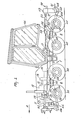
- the tractor shown in the Figures comprises a frame 1 having a front frame part 2 and a rear frame part 3, which are movable with respect to each other.
- the front frame part 2 is made of hollow, tubular beams having plate-shaped wall or steel or light metal.
- the front frame part 2 comprises two substantially horizontal, hollow beams 4 and 5 located at equal distances from the vertical plane of symmetry 6 of the tractor.
- the hollow beams 4 and 5 are rigidly interconnected at the front, viewed with respect to the direction of movement A, by means of a horizontal hollow beam (not shown) and at their rear ends also by means of ⁇ a substari- tially horizontal hollow beam 7 extending transversely of the direction of movement.
- the beams 4 and 5 are provided with bearings 8 intended to hold a tandem axle 9, which is substantially horizontal and extends transversely to the direction of movement A.
- an engine is mounted, preferably a Diesel-engine, said engine being located in front of the main wheel axle 9.
- a cooling system 11 is mounted approximately above the beam between the hollow beams 4 and 5.
- the engine 10 On the rear side the engine 10 has an outlet shaft 12 which extends, viewed in plan, over and across the main wheel axle 9 and is connected at the rear end with an input shaft of a gear box 13 being made of steel metal.
- the output shaft 14 is connected at its rear end with the input shaft of a variabel hydraulic pump 15.
- the output shaft 14 is located, as viewed in plan, parallel to and at a distance from the centre line of the output shaft 12 of the engine 10.
- the gear box 13 has a second output shaft 16 which is located, in side view, below the output shaft 14.
- the front frame part 2 comprises a bearing 17 (fig.2), which is rigidly secured to the rear side of the beam 7.
- the bearing 17 has a centre line located in the vertical plane of symmetry 6 of the tractor in a substantially horizontal position.
- This bearing may comprise a bearing bushing and/or ball or roller bearings.
- the front end of a hollow beam 18 is pivotable in the bearing 17.
- the hollow beam 18 being part of a frame part 3 is provided with a substantial horizontally extending tandem axle 20, said axle extending transversely of the direction of movement.
- the centre line of the top lifting arm 23 is substantially located in the plane of symmetry 6.
- the centre lines of the tandem axles 9 and 20 are located in the same, substantially horizontal plane.
- pivotal shafts 24 are arranged horizontally and transversely to the direction of movement A.
- the pivotal shafts 24 carry lower lifting arms 25 of a foremost lifting device 26.
- the hollow beams 4 and 5 are provided at the sides of the engine 10 with upwardly extending supports 27, said supports having pivotal shafts 28, holding the upper lifting arms 29 extending in a forward direction and being located one on each side of the cooling system 11 of the engine 10.
- the upper lifting arms 29 are interconnected by a horizontal hollow beam 30 to which the upper coupling point 45 of the lifting device 26 is connected.
- each tandem wheel support 31 is freely pivotable about the axle 9 and, viewed in plan, is symmetrical to the centre line of the axis 9.
- a wheel support 33 To each of the front and rear parts of the central part 32 is rigidly secured a wheel support 33.
- Each wheel . support 33 is outwardly and downwardly inclined away from the central part 32 and its free end is provided with an upwardly directed axis about which a tractor wheel 35 is steerable.
- Each of the assemblies located one on each side of the front frame part 2 and comprising the central part 32, the two wheel supports 33, the pivotal shafts 34 and the two ground wheels 35 constitutes a tandem wheel set.
- Each ground wheel 35 can be driven by means of a hydraulic motor 36.
- the motors 36 are fed by the variable pump 15 driven by the engine 10.
- the centre line of the hydraulic motors is about in line with the axle of a wheel.
- the two tandem wheel sets 32 to 36 located each on one side of the frame part 2 are pivotable about the main wheel axle 9 independently of one another.
- tandem wheel sets are mounted to the rear frame part 3.
- a central part 37 is pivotable about the tari- dem axle 20 and is provided with wheel supports 38, which extend, viewed in plan, outwardly and downwardly with respect to the centre line of the tandem axle 20.
- wheel supports 38 which extend, viewed in plan, outwardly and downwardly with respect to the centre line of the tandem axle 20.
- At their free ends they carry substantially vertical pivotal axis 39, about which a tractor wheel 40 is pivotable.
- Each wheel 40 is steerable and can be driven by means of a hydraulic motor 41, which is fed by the pump 15.
- the planes of symmetry of the wheels 35 and 40 located on one side of the tractor frame are coplanar and the four tandem wheel sets are about identical of design.
- the diameters of all tractor wheels 35 and 40 are about the same, at least in this embodiment.
- the foremost lifting device 26 or the rearmost lifting device 21 is provided with a hitching member 42 and 43, the hitching member 43 being of heavy weight and the hitching member 42 having a usual weight.
- hitching members may, as an alternative, be arranged in the inverse order, i.e. hitching member 42 on the rearmost lifting device 21 and hitching member 43 on the foremost lifting device 26 can be used on both lifting devices.
- only one of the two hitching members 42 or 43 may be fastened to the foremost or to the rearmost lifting device and, as a further alternative, the two hitching members may not be fastened to the tractor at all, depending on the jobs to be carried out.
- both hitching members and implements can be directly hitched to the lifting devices 21 of 26. If there is a danger of excessive wheel slippage it is preferred to attach the hitching member 43 to the foremost or the rearmost lifting device or to provide the two lifting devices with a heavy hitching member 43 each.
- the coupling points of the two lifting devices are of the same design and have the same relative distances.
- the hitching member 42 has the shape of an inverted U and is made of tubular material of light weight (weight about 50 kgs). On its side facing the tractor and at both lower ends, the hitching member 42 has pin-shaped coupling points for attaching the hitching member to the two lower lifting arms 25 of the lifting device of the tractor, said arms having for this purpose hooks 44 opening up in upward direction: In the plane of symmetry of the hitching member 42 and on the top side thereof, a pin extends horizontally and transversely of the direction of movement, about which pin can grasp a hook 45 being pivotally connected to the beam 30 of the upper arms of the lifting device 26, midway the length of said beam.
- the hitching member 42 On its side remote from the tractor the hitching member 42 is provided with two hooks 46 opening in upward direction, each of which is arranged near a lower end of the U-shaped hitching member 42, whilst midway along the length of the horizontal tube of the U-shaped hitching member 42 there is fastened a hook 47 opening in upward direction, which is located in the plane of symmetry 6, when the coupling member is attached to the tractor.
- the hooks 44 constitute the coupling points of the lifting device 26.
- the hitching member 43 has a rectangular shape, the sides of which are formed by solid steel bars having a cross-section of about 20 x 30 cms.
- the weight of the hitching member 43 is preferably about 1000 kgs.
- the hitching member 43 is provided with laterally protruding pins adapted to connect in the hooks 48 opening up in upward direction and arranged at the free ends of the lower lifting arms 20A of the lifting device 21.
- the hooks 48 constitute the coupling points of- the lifting device 21.
- Midway the length of an upper, horizontal bar of the hitching member 43 ears are provided supporting a horizontal pin extending transversely of the direction of movement for connecting to the end of the upper lifting arm of the lifting device.
- the hitching member 43 On the side remote of the tractor and at the outer and lower parts the hitching member 43 is provided with hooks 49 opening up in upward direction and located at a distance from and symmetrically to the plane of symmetry when the hitching member 43 is fastened to the tractor. Midway the length of the horizontal upper beam of the hitching member 43 a rearwardly extending hook is arranged which is also opening up in upwardly direction.
- the hooks 46 and 47 of the hitching member 42 and the hooks 49 and 50 of the hitching member 43 which constitute three-point coupling systems, implements can be hitched to the hitching members 42 or 43 respectively at the front and/or at the rear of the tractor.
- a draw hook 51 is provided for pulling waggons or implements.
- the second output shaft 16 of the gear box 13 which is located, as viewed in plan, below the output shaft of the engine 10 is connected with a forwardly directed shaft, extending out of the frame at the front of the tractor to form a power take-off shaft 52 for driving implements hitched to the foremost lifting device 26. Furthermore, the output shaft 16 of the gearbox 13 extends to the rear and forms an intermediate shaft 52, at the rear side of which, a gear box 53 of steel metal is mounted, said gear box being connected to the rear side of the hollow beam 18, and having an input shaft 54, which is located above the hollow beam 18.
- the intermediate shaft 52 is drivably connected by means of universal couplings with the output shaft 16 of the gear box 13 and with the input shaft 54 of the gear box 53.
- the gear box 53 has an output shaft 55 located approximately at the level of the hollow beam 18 and serving as a power take-off shaft for driving implements attached to the rear lifting device 21.
- the engine 10, the gear box 13 and the hydraulic pump 15 are surrounded by cover 56, which, viewed from aside, ter- nimates approximately at a vertical plane extending transversely of the direction of movement A comprising the rearmost points of the rearmost wheels 35.
- cover 56 Above the rear part of the frame part 2 is mounted the driver cabin which extends, as viewed from aside, from the rearmost points of the rearmost wheels 35 up to the axle of the rearmost wheels 40.
- the overall length of the cabin 56, measured in the direction of length of the tractor is about 200 cms. This length may be equal to about half the overall length of the.tractor. Since the rear frame part 3 is pivotable with respect to the front frame part 2, the cabin is not connected to the rear frame part 3.
- the inner height of the cabin 56 above the floor is about 190 cms.
- the driver in the cabin can see from his seat the coupling points of the lifting device 21 as well as the ground directly adjacent the tractor wheels.
- the width of the cabin is preferably substantially equal to the track of the tractor being about 180 cms.
- the free space underneath the tractor is about 60 cms.
- the overall weight of the tractor without hitching members 42, 43 is about 2000 kgs.
- the weight of the tractor is 40 kgs per kilowatt engine power.
- the wheels are equipped with pneumatic tyres having a diameter of about 100 cms . and a width of about 40 cms so that the diameter is about two times or about two and a half times the width of the pneumatic tyre.
- the contact surface of each tyre on the ground is about 40 x 40 cms under average ground conditions (ground pressure about 0.16 kg per square centimetre).
- the tractor weight per wheel would be about 500 kgs. It is important that the force exerted by a wheel on the ground will have approximately the same value of all tractor wheels.
- the tractor is equipped with four tandem wheel sets arranged pairwise on each side of the tractor, independently pivotable about the axle 9 and the axle 20 respectively.
- the uniformity of the ground pressure between the wheels and the ground is further improved by the rear frame part 3 being pivotable about a horizontal axis extending in the direction of movement A.
- the distribution of the weight of the tractor over its length also is important.
- the mounting of the engine, the gear box 13 and the hydraulic pump 15 on the front part of the tractor frame and on the other hand the weight of the cabin 56 on the rear part of the frame contribute to the uniform distribution of the weight on all tractor wheels.
- the engine power of the engine 10 is at least 30 kW and is in this embodiment preferably about 60 kW.
- the diameter of the tractor wheels 35 and 40 is about 100 cms.
- the eight wheels can exert sufficient tractive force against the ground driver's view on the implement is not obstructed.
- the track of the tractor in this embodiment is about 180 cms.
- the overall length of the tractor with attached hitching members 42 and 43, i.e. the distance between the coupling hooks 46, 47 and 49, 50 respectively, is about 5 metres.
- the low weight of the tractor is caused by the use of the light hollow frame beams, a light hydraulic drive for driving the tractor wheels and light wheels of a small diameter so that light axles can be applied, this to the contrary of the cast iron frame and very large wheels on the commercial tractors presently available.
- the frame usually consists of a cast iron transmission housing connected to the engine and a cast iron rear axle connected to the cast iron transmission housing.
- the axles of wheels areof a very large diameter as these axles must drive large and slowly revolving tractor wheels.
- the tractor embodying the invention has a low weight and this tractor can, if desired, be provided with one or two hitching members of the type described for the hitching member 43, e.g. when the tractor has to pull a heavy waggon or a heavy pull type implement not being power driven. For pulling waggons or implements the hitching member 43 is provided with the drawhook 51.
- the lifting capacity of the tractor is about 4000 kgs. and the lifting power of the rearmost lifting device is about 3000 kgs. or more.
- the lifting devices of the tractor are designed in such a way that they will be capable of connecting hitching members 42 and 43 (or an implement) picking them up from the ground without further assistance.
- the coupling points are about 12 cm above the ground. Owing to the length of the tractor and if the weight of the front part 2 of the tractor will be only 1000 kgs, the lifting power at the coupling points of the rear lifting device 21 will be about 5000 kgs. The length of the tractor therefore permits the tractor to lift large power driven implements without compacting the soil as the weight of the tractor is in comparison with the usual tractors low.
- the tractor wheels are relatively small and as the coupling points of the lifting device-are, viewed from aside, as usual directly behind the wheels, the tractor has a higher lifting power than usual.
- the tractor according to the invention is especially suitable for seedbed preparation, however, can be used for other farm operations in which low ground pressure and high engine power is of advantage.
- the main advantage of the tractor is to be found in the high power at the power take-off shafts, the low ground pressure of the tractor wheels_ and the excellent lifting capacity of the tractor.
- the tractor is provided with hydraulic motors for driving the tractor wheels.
- the engine of the tractor can be used to its maximum extent for driving the power driven implements.
- the hydraulic drive being continuously variable the forward speed of the tractor can easily be adjusted, giving maximum operating efficiency.
- the tractor has a three-point lifting device with a lifting power at its coupling points of about one and a halve times the weight of the tractor.
Abstract
A tractor for agricultural purposes or the like comprises an engine (10), a frame (1), at least two power driven wheels (35,40), at least one lifting device (21) and at least one power take-off shaft (55).
The tractor has a low weight and comprises a ballast weight (43). The ballast weight is provided with coupling means for attaching at least one implement to the ballast weight.
Description
- The invention relates to a tractor for agricultural purposes or the like comprising an engine, a frame, at least two power driven wheels, at least one lifting device and at least one power take-off shaft.
- In the present development of such agricultural tractors there can be observed a tendency in the following directions.
- 1. ever larger engines,
- 2. ever larger wheels requiring a heavier power train,
- 3. ever heavier tractors,
- 4. more use of heavy cast iron as basic parts of the tractor.
- It is neglected, however, that the ever heavier tractors adversely affect the structure and the productivity of the soil.
- The heavy tractors are compacting the soil excessively. The drainage of the surface water into the soil will be negatively affected. Hard clods will be formed when the soil dries up. This is resulting in a deterioration of the soil structure, decreasing the productivity.
- A further disadvantage of the heavier tractors is that the power required by the tractor for moving itself through the field will become higher. Under average field conditions and especially during seedbed preparation and under soft soil working conditions a tractor will use more than fifty percent of its engine power to move itself through the field. This means that less than fifty percent of the engine power will be available at the power take-off shaft. The need for more power requires a larger engine. A heavier engine however increases the tractor weight, which again requires an increase in engine power causing a vicious circle. Therefore the present thinking how to design a tractor is going in the wrong direction. In addition to this the consumption of expensive fuel is becoming excessive.
- It is an object of the invention to avoid these disadvantages.
- According to the present invention there is provided a tractor as described in the first paragraph, whereby the tractor has a low weight and comprises a ballast weight, said ballast weight being provided with coupling means for attaching at least one implement to the ballast weight.
- A tractor according to the invention has the advantage that it can be adapted easily to various circumstances e.g. without ballast weight the tractor can prepare a seedbed very efficiently and with the ballast weight can pull a waggon or an implement under difficult circumstances.
- According to another aspect of the invention such tractor has a lifting device and a hitching device designed in such a way that the lifting device can pick up a hitching member without further assistance.
- Such tractor has the special advantage that the heavy weight hitching member can easily be picked up and connected to the tractor.
- For a better understanding of the invention and in order to show how the same may be carried into effect, reference will be made by way of example to the accompanying drawings.
- The tractor shown in the Figures comprises a frame 1 having a front frame part 2 and a
rear frame part 3, which are movable with respect to each other. The front frame part 2 is made of hollow, tubular beams having plate-shaped wall or steel or light metal. The front frame part 2 comprises two substantially horizontal,hollow beams 4 and 5 located at equal distances from the vertical plane of symmetry 6 of the tractor. Thehollow beams 4 and 5 are rigidly interconnected at the front, viewed with respect to the direction of movement A, by means of a horizontal hollow beam (not shown) and at their rear ends also by means of· a substari- tially horizontalhollow beam 7 extending transversely of the direction of movement. Near theengine 10 thebeams 4 and 5 are provided with bearings 8 intended to hold atandem axle 9, which is substantially horizontal and extends transversely to the direction of movement A. On thehollow beams 4 and 5 an engine is mounted, preferably a Diesel-engine, said engine being located in front of themain wheel axle 9. At the front side of the engine 10 acooling system 11 is mounted approximately above the beam between thehollow beams 4 and 5. - On the rear side the
engine 10 has anoutlet shaft 12 which extends, viewed in plan, over and across themain wheel axle 9 and is connected at the rear end with an input shaft of agear box 13 being made of steel metal. The output shaft 14 is connected at its rear end with the input shaft of a variabelhydraulic pump 15. The output shaft 14 is located, as viewed in plan, parallel to and at a distance from the centre line of theoutput shaft 12 of theengine 10. Thegear box 13 has a second output shaft 16 which is located, in side view, below the output shaft 14. - The front frame part 2 comprises a bearing 17 (fig.2), which is rigidly secured to the rear side of the
beam 7. Thebearing 17 has a centre line located in the vertical plane of symmetry 6 of the tractor in a substantially horizontal position. This bearing may comprise a bearing bushing and/or ball or roller bearings. The front end of ahollow beam 18 is pivotable in thebearing 17. - The
hollow beam 18 being part of aframe part 3 is provided with a substantial horizontally extendingtandem axle 20, said axle extending transversely of the direction of movement. To the rear side of thesupports 19 bearings are arranged for the lower liftingarms 20A of a three-point lifting device 21, said arms also being symmetrical to the plane of symmetry 6. To thehollow beam 18 there are connected rearwardly and upwardly extendingears 22, the free end of which carry a pivotal shaft for the top lifting arm <23 of thelifting device 21. The centre line of thetop lifting arm 23 is substantially located in the plane of symmetry 6. When the tractor is on a horizontal surface, the centre lines of thetandem axles - On both sides of the
hollow beams 4 and 5 of the front frame part 2, and as viewed in plan, approximately near the rear side of theengine 10pivotal shafts 24 are arranged horizontally and transversely to the direction of movement A. Thepivotal shafts 24 carry lower liftingarms 25 of aforemost lifting device 26. Thehollow beams 4 and 5 are provided at the sides of theengine 10 with upwardly extendingsupports 27, said supports having pivotal shafts 28, holding the upper liftingarms 29 extending in a forward direction and being located one on each side of thecooling system 11 of theengine 10. At their front ends the upper liftingarms 29 are interconnected by a horizontalhollow beam 30 to which theupper coupling point 45 of thelifting device 26 is connected. - At the ends of the
tandem axle 9 the tandem wheel supports 31 are attached. Acentral part 32 of eachtandem wheel support 31 is freely pivotable about theaxle 9 and, viewed in plan, is symmetrical to the centre line of theaxis 9. To each of the front and rear parts of thecentral part 32 is rigidly secured awheel support 33. Each wheel .support 33 is outwardly and downwardly inclined away from thecentral part 32 and its free end is provided with an upwardly directed axis about which atractor wheel 35 is steerable. Each of the assemblies located one on each side of the front frame part 2 and comprising thecentral part 32, the two wheel supports 33, thepivotal shafts 34 and the twoground wheels 35 constitutes a tandem wheel set. Eachground wheel 35 can be driven by means of ahydraulic motor 36. Themotors 36 are fed by thevariable pump 15 driven by theengine 10. The centre line of the hydraulic motors is about in line with the axle of a wheel. The two tandem wheel sets 32 to 36 located each on one side of the frame part 2 are pivotable about themain wheel axle 9 independently of one another. - In about the same manner tandem wheel sets are mounted to the
rear frame part 3. On each side of the vertical plane of symmetry 6 acentral part 37 is pivotable about the tari-dem axle 20 and is provided withwheel supports 38, which extend, viewed in plan, outwardly and downwardly with respect to the centre line of thetandem axle 20. At their free ends they carry substantially verticalpivotal axis 39, about which atractor wheel 40 is pivotable. Eachwheel 40 is steerable and can be driven by means of ahydraulic motor 41, which is fed by thepump 15. The planes of symmetry of thewheels tractor wheels - In the arrangement shown the
foremost lifting device 26 or therearmost lifting device 21 is provided with a hitchingmember member 43 being of heavy weight and the hitchingmember 42 having a usual weight. These hitching members may, as an alternative, be arranged in the inverse order, i.e. hitchingmember 42 on therearmost lifting device 21 and hitchingmember 43 on theforemost lifting device 26 can be used on both lifting devices. Moreover, only one of the two hitchingmembers lifting devices 21 of 26. If there is a danger of excessive wheel slippage it is preferred to attach the hitchingmember 43 to the foremost or the rearmost lifting device or to provide the two lifting devices with a heavy hitchingmember 43 each. The coupling points of the two lifting devices are of the same design and have the same relative distances. - Viewed in the direction of movement A the hitching
member 42 has the shape of an inverted U and is made of tubular material of light weight (weight about 50 kgs). On its side facing the tractor and at both lower ends, the hitchingmember 42 has pin-shaped coupling points for attaching the hitching member to the twolower lifting arms 25 of the lifting device of the tractor, said arms having for this purpose hooks 44 opening up in upward direction: In the plane of symmetry of the hitchingmember 42 and on the top side thereof, a pin extends horizontally and transversely of the direction of movement, about which pin can grasp ahook 45 being pivotally connected to thebeam 30 of the upper arms of thelifting device 26, midway the length of said beam. On its side remote from the tractor the hitchingmember 42 is provided with twohooks 46 opening in upward direction, each of which is arranged near a lower end of the U-shaped hitchingmember 42, whilst midway along the length of the horizontal tube of the U-shaped hitchingmember 42 there is fastened ahook 47 opening in upward direction, which is located in the plane of symmetry 6, when the coupling member is attached to the tractor. Thehooks 44 constitute the coupling points of thelifting device 26. - Viewed in the direction of movement the hitching
member 43 has a rectangular shape, the sides of which are formed by solid steel bars having a cross-section of about 20 x 30 cms. The weight of the hitchingmember 43 is preferably about 1000 kgs. Near its outer and lower ends the hitchingmember 43 is provided with laterally protruding pins adapted to connect in thehooks 48 opening up in upward direction and arranged at the free ends of thelower lifting arms 20A of thelifting device 21. Thehooks 48 constitute the coupling points of- thelifting device 21. Midway the length of an upper, horizontal bar of the hitchingmember 43 ears are provided supporting a horizontal pin extending transversely of the direction of movement for connecting to the end of the upper lifting arm of the lifting device. On the side remote of the tractor and at the outer and lower parts the hitchingmember 43 is provided withhooks 49 opening up in upward direction and located at a distance from and symmetrically to the plane of symmetry when the hitchingmember 43 is fastened to the tractor. Midway the length of the horizontal upper beam of the hitching member 43 a rearwardly extending hook is arranged which is also opening up in upwardly direction. By means of thehooks member 42 and thehooks member 43, which constitute three-point coupling systems, implements can be hitched to the hitchingmembers draw hook 51 is provided for pulling waggons or implements. - The second output shaft 16 of the
gear box 13, which is located, as viewed in plan, below the output shaft of theengine 10 is connected with a forwardly directed shaft, extending out of the frame at the front of the tractor to form a power take-offshaft 52 for driving implements hitched to theforemost lifting device 26. Furthermore, the output shaft 16 of thegearbox 13 extends to the rear and forms anintermediate shaft 52, at the rear side of which, agear box 53 of steel metal is mounted, said gear box being connected to the rear side of thehollow beam 18, and having aninput shaft 54, which is located above thehollow beam 18. Theintermediate shaft 52 is drivably connected by means of universal couplings with the output shaft 16 of thegear box 13 and with theinput shaft 54 of thegear box 53. Thegear box 53 has anoutput shaft 55 located approximately at the level of thehollow beam 18 and serving as a power take-off shaft for driving implements attached to therear lifting device 21. - The
engine 10, thegear box 13 and thehydraulic pump 15 are surrounded bycover 56, which, viewed from aside, ter- nimates approximately at a vertical plane extending transversely of the direction of movement A comprising the rearmost points of therearmost wheels 35. Above the rear part of the frame part 2 is mounted the driver cabin which extends, as viewed from aside, from the rearmost points of therearmost wheels 35 up to the axle of therearmost wheels 40. The overall length of thecabin 56, measured in the direction of length of the tractor, is about 200 cms. This length may be equal to about half the overall length of the.tractor. Since therear frame part 3 is pivotable with respect to the front frame part 2, the cabin is not connected to therear frame part 3. The inner height of thecabin 56 above the floor is about 190 cms. The driver in the cabin can see from his seat the coupling points of thelifting device 21 as well as the ground directly adjacent the tractor wheels. The width of the cabin is preferably substantially equal to the track of the tractor being about 180 cms. The free space underneath the tractor is about 60 cms. - In connection with the invention the following additional data are of importance.
- The overall weight of the tractor without hitching
members axle 9 and theaxle 20 respectively. The uniformity of the ground pressure between the wheels and the ground is further improved by therear frame part 3 being pivotable about a horizontal axis extending in the direction of movement A. The distribution of the weight of the tractor over its length also is important. The mounting of the engine, thegear box 13 and thehydraulic pump 15 on the front part of the tractor frame and on the other hand the weight of thecabin 56 on the rear part of the frame contribute to the uniform distribution of the weight on all tractor wheels. - The engine power of the
engine 10 is at least 30 kW and is in this embodiment preferably about 60 kW. The diameter of thetractor wheels members - The low weight of the tractor is caused by the use of the light hollow frame beams, a light hydraulic drive for driving the tractor wheels and light wheels of a small diameter so that light axles can be applied, this to the contrary of the cast iron frame and very large wheels on the commercial tractors presently available. In such tractors the frame usually consists of a cast iron transmission housing connected to the engine and a cast iron rear axle connected to the cast iron transmission housing. The axles of wheels areof a very large diameter as these axles must drive large and slowly revolving tractor wheels.
- The tractor embodying the invention has a low weight and this tractor can, if desired, be provided with one or two hitching members of the type described for the hitching
member 43, e.g. when the tractor has to pull a heavy waggon or a heavy pull type implement not being power driven. For pulling waggons or implements the hitchingmember 43 is provided with thedrawhook 51. - For carrying out seedbed preparation with.power driven implements (when the weight of the tractor has to be as low as possible) not any heavy hitching member will be attached to the tractor.
- The lifting capacity of the tractor is about 4000 kgs. and the lifting power of the rearmost lifting device is about 3000 kgs. or more.
- The lifting devices of the tractor are designed in such a way that they will be capable of connecting hitching
members 42 and 43 (or an implement) picking them up from the ground without further assistance. The coupling points are about 12 cm above the ground. Owing to the length of the tractor and if the weight of the front part 2 of the tractor will be only 1000 kgs, the lifting power at the coupling points of therear lifting device 21 will be about 5000 kgs. The length of the tractor therefore permits the tractor to lift large power driven implements without compacting the soil as the weight of the tractor is in comparison with the usual tractors low. - As the tractor wheels are relatively small and as the coupling points of the lifting device-are, viewed from aside, as usual directly behind the wheels, the tractor has a higher lifting power than usual.
- The tractor according to the invention is especially suitable for seedbed preparation, however, can be used for other farm operations in which low ground pressure and high engine power is of advantage. The main advantage of the tractor is to be found in the high power at the power take-off shafts, the low ground pressure of the tractor wheels_ and the excellent lifting capacity of the tractor.
- Preferably the tractor is provided with hydraulic motors for driving the tractor wheels. In such case the engine of the tractor can be used to its maximum extent for driving the power driven implements. With the hydraulic drive being continuously variable the forward speed of the tractor can easily be adjusted, giving maximum operating efficiency.
- Preferably the tractor has a three-point lifting device with a lifting power at its coupling points of about one and a halve times the weight of the tractor.
- The invention not only relates to the statements made in the foregoing and. in the claims, but also encompasses the details of the figures.
Claims (29)
1. A tractor for agricultural purposes or the like comprising an engine (10), a frame (1), at least two power driven wheels (35, 40), at least one lifting device (21,26) and at least one power take-off shaft (52, 55), characterized in that the tractor has a low weight and comprises a ballast weight (42,43), said ballast weight being provided with coupling means (46,47,49,50,51) for attaching at least one implement to the ballast weight.
2. A tractor as claimed in claim 1, characterized in that the ballast weight (42,43) is a hitching member to which agricultural implements can be connected.
3. A tractor as claimed in claim 1 or 2, characterized in that-the ballast weight (42,43) of the tractor is provided with coupling means for attaching the ballast weight to the lifting device (21,26) of the tractor.
4. A tractor as claimed in anyone of claims 1 - 3,characterized in that the ballast weight (42, 43) may be coupled with the front lifting device (26) as well as with the rear lifting device (21) of the tractor.
5. A tractor as claimed in anyone of the preceding claims, characterized in that the-ballast weight (43) is provided with a drawhook (51) for drawing an implement or a vehicle.
6. A tractor as claimed in anyone of the preceding claims, characterized in that the coupling means (42,43) comprise hooks (46,47,49,50) opening in upward direction.
7. A tractor as claimed in anyone of the preceding claims, characterized in that the ballast weight (43) comprises one or more solid steel bars.
8. A tractor as claimed in anyone of the preceding claims, characterized in that a hitching member or implement (42,43) having its coupling points at about 12 cms above the ground in such a way that is can be attached to the lifting device (21,26) by means of the lifting device exclusively.
9. A tractor as claimed in anyone of the preceding claims, characterized in that the lifting device (21,26) and a hitching member (42,43) are designed in such a way that the lifting device can pick up the hitching member without further assistance.
10. A tractor for agricultural purposes or the like comprising an engine (10), a frame (1), at least two power driven wheels (35,40), at least one lifting device (21,26) and at least one power take-off shaft (52,55), characterized in that the lifting device (21,26) and a hitching member (42, 43) are designed in such a way that the lifting device can pick up the hitching member without further assistance.
11. A tractor as claimed in anyone of the preceding claims, characterized in that-..the coupling points of the hitching member (42,43) are at about 12 cms above the ground.
12. A tractor as claimed in anyone of the preceding claims, characterized in that the length of the tractor inclusive the lifting devices (21,26) is about 500 cms.
13. A tractor as claimed in anyone of the preceding claims, characterized in that the power of the tractor engine (10) is about 60 kW.
14. A tractor as claimed in anyone of the preceding claims, characterized in that the tractor has tyres having a diameter being about two and a half times the width of a tyre.
15. A tractor as claimed in anyone of the preceding claims, characterized in that the tractor has a lifting device (21,26) and a power take-off shaft (52,55) at its front end and at the rear.
16. A tractor as claimed in anyone of the preceding claims, characterized in that the lifting power of a lifting device (21,26) is at its coupling points about 2000 kgs.
17. A tractor as claimed in anyone of the preceding claims, characterized in that the coupling points of the lifting device (21) are viewed from aside directly behind the wheels of about 100 cms diameter.
18. A tractor as claimed in anyone of the preceding claims, characterized in that the weight of the tractor is about 2000 kgs.
19. A hitching member having means for coupling the same to the lifting device (21,26) of a tractor, said hitching member having means for attaching an implement to the hitching member, characterized in that the hitching member (43) comprises a weight serving as ballast to increase the pressure of the tractor onto the ground.
20. A hitching member as claimed in claim 19, characterized in that the ballast weight (42,43) has coupling means for hitching an implement to the ballast weight.
21. A hitching member having means for coupling the same to the lifting device (21,26) of a tractor, said hitching member having means for attaching an implement to the hitching member, characterized in that the hitching member (43) is provided with a drawhook (51) to which an implement or a waggon can be hitched.
22. A ballast weight for a tractor, characterized in that the ballast weight (42,43) is provided with coupling menas for connecting it with the coupling points (44,45,48,
23) of a hydraulic lifting device (21,26) of a tractor.
23. A ballast weight for a tractor, characterized in that the ballast weight (42,43) has coupling means (46,47, 49,50,51) for hitching an implement to the ballast weight.
24. A tractor as illustrated in the drawings.
25. A hitching member as described.
26. A hitching member as illustrated in the drawings.
27. A ballast weight as described.
28. A ballast weight as illustrated in the drawings.
Applications Claiming Priority (2)
| Application Number | Priority Date | Filing Date | Title |
|---|---|---|---|
| NL8200663 | 1982-02-19 | ||
| NL8200663A NL8200663A (en) | 1982-02-19 | 1982-02-19 | TRACTOR FOR AGRICULTURAL PURPOSES OR THE LIKE. |
Publications (2)
| Publication Number | Publication Date |
|---|---|
| EP0087203A2 true EP0087203A2 (en) | 1983-08-31 |
| EP0087203A3 EP0087203A3 (en) | 1985-05-02 |
Family
ID=19839288
Family Applications (3)
| Application Number | Title | Priority Date | Filing Date |
|---|---|---|---|
| EP83200251A Withdrawn EP0087203A3 (en) | 1982-02-19 | 1983-02-18 | Low-weight agricultural tractor with removable implement coupling and ballasting means |
| EP83200250A Withdrawn EP0087202A3 (en) | 1982-02-19 | 1983-02-18 | Multipurpose agricultural tractor with low ground pressure |
| EP83200249A Ceased EP0087201A3 (en) | 1982-02-19 | 1983-02-18 | Light agricultural tractor with high lifting and power take off capability |
Family Applications After (2)
| Application Number | Title | Priority Date | Filing Date |
|---|---|---|---|
| EP83200250A Withdrawn EP0087202A3 (en) | 1982-02-19 | 1983-02-18 | Multipurpose agricultural tractor with low ground pressure |
| EP83200249A Ceased EP0087201A3 (en) | 1982-02-19 | 1983-02-18 | Light agricultural tractor with high lifting and power take off capability |
Country Status (7)
| Country | Link |
|---|---|
| US (3) | US4523656A (en) |
| EP (3) | EP0087203A3 (en) |
| JP (2) | JPS58152676A (en) |
| DE (3) | DE3305372A1 (en) |
| FR (1) | FR2521941B1 (en) |
| GB (1) | GB2115760B (en) |
| NL (1) | NL8200663A (en) |
Cited By (1)
| Publication number | Priority date | Publication date | Assignee | Title |
|---|---|---|---|---|
| US9957001B1 (en) | 2016-11-02 | 2018-05-01 | Deere & Company | Ballast assembly for a work vehicle |
Families Citing this family (12)
| Publication number | Priority date | Publication date | Assignee | Title |
|---|---|---|---|---|
| NL8200663A (en) * | 1982-02-19 | 1983-09-16 | Lely Nv C Van Der | TRACTOR FOR AGRICULTURAL PURPOSES OR THE LIKE. |
| NL8203727A (en) * | 1982-09-27 | 1984-04-16 | Lely Nv C Van Der | TRACTOR, IN PARTICULAR A TRACTOR FOR AGRICULTURAL PURPOSES. |
| GB2150511B (en) * | 1983-11-29 | 1987-07-29 | Esarco Ltd | Four axle all-terrain vehicle |
| AT388362B (en) * | 1986-06-24 | 1989-06-12 | Steyr Daimler Puch Ag | A LIFTING GEAR ARRANGED ON AN AGRICULTURAL COMMERCIAL VEHICLE FOR THE OPTIONAL ATTACHMENT OF EQUIPMENT PROVIDED WITH CONNECTING PINS OR BOLTS |
| US4967863A (en) * | 1987-05-15 | 1990-11-06 | Deere & Company | Compact combine drive system |
| US5092422A (en) * | 1989-12-12 | 1992-03-03 | Clemson University | Multipurpose agricultural tractor |
| US5152364A (en) * | 1991-03-08 | 1992-10-06 | Deere & Company | Tractor configuration and component mounting arrangement for high visibility, maneuverability, and serviceability |
| GB9818316D0 (en) | 1998-08-21 | 1998-10-14 | Borealis As | Polymer |
| DE10033261A1 (en) * | 2000-07-11 | 2002-01-24 | Macmoter Spa | vehicle |
| JP3717428B2 (en) * | 2001-07-19 | 2005-11-16 | 株式会社クボタ | Tractor with cabin |
| US8534412B2 (en) * | 2007-10-08 | 2013-09-17 | Custom Chassis, Inc. | Multipurpose utility vehicle |
| GB2457248A (en) * | 2008-02-06 | 2009-08-12 | Agco Sa | Tractor counterweight assembly |
Citations (12)
| Publication number | Priority date | Publication date | Assignee | Title |
|---|---|---|---|---|
| US2247680A (en) * | 1938-04-19 | 1941-07-01 | Int Harvester Co | Agricultural implement |
| US2440550A (en) * | 1942-05-13 | 1948-04-27 | Howard B Rapp And Sally Rapp | Tractor-conveyed implement and hitch therefor |
| US2891681A (en) * | 1956-12-05 | 1959-06-23 | Caterpillar Tractor Co | Rotatable counterweight mechanism |
| US3135404A (en) * | 1962-06-27 | 1964-06-02 | Ware Machine Works Inc | Tractor mounted counterweight |
| US3220582A (en) * | 1964-12-10 | 1965-11-30 | John S Pilch | Tractor mounted counterweight |
| US3480294A (en) * | 1966-09-20 | 1969-11-25 | Walter Lichti | Tractor control device |
| US3595410A (en) * | 1969-08-18 | 1971-07-27 | Deere & Co | Tractor-mounted power assist means for elevating front-end weights |
| FR2117159A5 (en) * | 1970-12-02 | 1972-07-21 | Kloeckner Humboldt Deutz Ag | |
| DE2232736A1 (en) * | 1972-07-04 | 1974-01-24 | Kloeckner Humboldt Deutz Ag | VEHICLE, IN PARTICULAR AGRICULTURAL AND / OR CONSTRUCTION INDUSTRY USEFUL MOTOR VEHICLE WITH COMPENSATING BALLAST |
| FR2327906A1 (en) * | 1975-10-16 | 1977-05-13 | Lely Nv C Van Der | TRACTOR |
| WO1979001026A1 (en) * | 1978-05-03 | 1979-11-29 | Ssab Svenskt Stal Ab | Weights for working and transport mechanisms |
| EP0083146A2 (en) * | 1981-12-29 | 1983-07-06 | Deere & Company | Vehicle with detachable ballast weight |
Family Cites Families (32)
| Publication number | Priority date | Publication date | Assignee | Title |
|---|---|---|---|---|
| BE502622A (en) * | 1951-04-18 | |||
| DE1002246B (en) | 1954-02-11 | 1957-02-07 | Fendt & Co Xaver | Front loader tractor |
| DE1138328B (en) | 1959-02-17 | 1962-10-18 | John Deere Lanz Ag | Frames for agricultural motor vehicles |
| US3154164A (en) * | 1961-10-12 | 1964-10-27 | Cochran Equipment Company | Off-highway tractor |
| US3358444A (en) * | 1965-07-16 | 1967-12-19 | Gen Motors Corp | Power transmission |
| US3409100A (en) * | 1966-04-04 | 1968-11-05 | Kronqvist Raimo Mikael | Vehicle with additional lifting wheels for steering |
| DE2055386C3 (en) * | 1969-11-14 | 1981-02-12 | Texas Industries Inc., Willemstad, Curacao (Niederlaendische Antillen) | Multi-blade tractor-mounted plow |
| DE2039668A1 (en) * | 1970-08-10 | 1972-02-17 | Kloeckner Humboldt Deutz Ag | Vehicle, in particular motor vehicle for agricultural use |
| CH550080A (en) * | 1972-01-04 | 1974-06-14 | Klaue Hermann | VEHICLE EQUIPPED WITH DRIVEN WHEELS, IN PARTICULAR TRACTOR. |
| US4105085A (en) * | 1973-10-22 | 1978-08-08 | Lely Cornelis V D | Tractors and other vehicles |
| NL7400508A (en) * | 1974-01-15 | 1975-07-17 | Lely Nv C Van Der | TRACTOR. |
| US3902735A (en) * | 1974-06-03 | 1975-09-02 | Caterpillar Tractor Co | Hydraulic counterweight removal mechanism |
| DE2443809C3 (en) * | 1974-09-13 | 1978-08-03 | Deere & Co., Moline, Ill. (V.St.A.), Niederlassung Deere & Co. European Office, 6800 Mannheim | Plate-shaped ballast weights, in particular for agricultural motor vehicles |
| NL7501076A (en) * | 1975-01-30 | 1976-08-03 | Lely Nv C Van Der | TRACTOR. |
| NL7501075A (en) * | 1975-01-30 | 1976-08-03 | Lely Nv C Van Der | TRACTOR. |
| US4153265A (en) * | 1975-06-05 | 1979-05-08 | Owens-Illinois, Inc. | Off-road vehicle |
| US4207956A (en) * | 1975-06-05 | 1980-06-17 | Owens-Illinois, Inc. | Apparatus for individually steering and driving vehicle wheels |
| US4223904A (en) * | 1975-06-05 | 1980-09-23 | Owens-Illinois, Inc. | Suspension assembly for off-road vehicle |
| NL7512128A (en) * | 1975-10-16 | 1977-04-19 | Lely Nv C Van Der | TRACTOR. |
| FR2340850A1 (en) * | 1976-02-10 | 1977-09-09 | Bidon Jacques | TRACTOR VEHICLE, ESPECIALLY FOR AGRICULTURAL USE |
| FR2376782A2 (en) | 1976-02-10 | 1978-08-04 | Bidon Jacques | TRACTOR VEHICLE, ESPECIALLY FOR AGRICULTURAL USE |
| GB1590461A (en) * | 1977-05-07 | 1981-06-03 | Ferranti Ltd | Agricultural tractors |
| US4237944A (en) * | 1978-01-17 | 1980-12-09 | Peavey Electronics Corporation | Method for forming the neck of a guitar |
| US4289214A (en) * | 1978-01-28 | 1981-09-15 | Spence William | Multi-purpose vehicle |
| AU526315B2 (en) * | 1978-01-28 | 1983-01-06 | Kubota Ltd. | A transmission fora farm tractor of four wheel drive type |
| US4350190A (en) * | 1978-08-17 | 1982-09-21 | Owens-Illinois, Inc. | Self propelled, off road vehicle |
| FR2448500A1 (en) * | 1979-02-07 | 1980-09-05 | Audureau Sa | Counterbalance weight for forklift truck - is mounted at rear of vehicle on swinging arms actuated by jack |
| FR2457630A1 (en) * | 1979-05-28 | 1980-12-26 | Taunay Maurice | Liquid fertiliser spreader for waterlogged ground - has sixteen driven wide tread wheels on two steering front and two fixed rear axles |
| US4549610A (en) * | 1979-06-05 | 1985-10-29 | Lely Cornelis V D | Vehicle with front and rear steerable wheels individually driven by hydraulic motors |
| US4309742A (en) * | 1980-01-22 | 1982-01-05 | International Harvester Company | Articulated tractor tire illumination arrangement |
| US4340240A (en) * | 1980-02-04 | 1982-07-20 | Anderson Ernest L | Three point hitch adaptor for a tractor |
| NL8200663A (en) * | 1982-02-19 | 1983-09-16 | Lely Nv C Van Der | TRACTOR FOR AGRICULTURAL PURPOSES OR THE LIKE. |
-
1982
- 1982-02-19 NL NL8200663A patent/NL8200663A/en not_active Application Discontinuation
-
1983
- 1983-02-16 GB GB08304272A patent/GB2115760B/en not_active Expired
- 1983-02-17 DE DE19833305372 patent/DE3305372A1/en not_active Withdrawn
- 1983-02-17 DE DE3305371A patent/DE3305371A1/en not_active Withdrawn
- 1983-02-17 JP JP58023908A patent/JPS58152676A/en active Pending
- 1983-02-17 DE DE19833305370 patent/DE3305370A1/en not_active Withdrawn
- 1983-02-17 JP JP58023909A patent/JPS58152677A/en active Pending
- 1983-02-18 EP EP83200251A patent/EP0087203A3/en not_active Withdrawn
- 1983-02-18 EP EP83200250A patent/EP0087202A3/en not_active Withdrawn
- 1983-02-18 FR FR8302690A patent/FR2521941B1/en not_active Expired
- 1983-02-18 EP EP83200249A patent/EP0087201A3/en not_active Ceased
- 1983-02-22 US US06/468,382 patent/US4523656A/en not_active Expired - Fee Related
-
1985
- 1985-03-25 US US06/715,208 patent/US4648472A/en not_active Expired - Fee Related
-
1987
- 1987-03-10 US US07/024,066 patent/US4754826A/en not_active Expired - Fee Related
Patent Citations (12)
| Publication number | Priority date | Publication date | Assignee | Title |
|---|---|---|---|---|
| US2247680A (en) * | 1938-04-19 | 1941-07-01 | Int Harvester Co | Agricultural implement |
| US2440550A (en) * | 1942-05-13 | 1948-04-27 | Howard B Rapp And Sally Rapp | Tractor-conveyed implement and hitch therefor |
| US2891681A (en) * | 1956-12-05 | 1959-06-23 | Caterpillar Tractor Co | Rotatable counterweight mechanism |
| US3135404A (en) * | 1962-06-27 | 1964-06-02 | Ware Machine Works Inc | Tractor mounted counterweight |
| US3220582A (en) * | 1964-12-10 | 1965-11-30 | John S Pilch | Tractor mounted counterweight |
| US3480294A (en) * | 1966-09-20 | 1969-11-25 | Walter Lichti | Tractor control device |
| US3595410A (en) * | 1969-08-18 | 1971-07-27 | Deere & Co | Tractor-mounted power assist means for elevating front-end weights |
| FR2117159A5 (en) * | 1970-12-02 | 1972-07-21 | Kloeckner Humboldt Deutz Ag | |
| DE2232736A1 (en) * | 1972-07-04 | 1974-01-24 | Kloeckner Humboldt Deutz Ag | VEHICLE, IN PARTICULAR AGRICULTURAL AND / OR CONSTRUCTION INDUSTRY USEFUL MOTOR VEHICLE WITH COMPENSATING BALLAST |
| FR2327906A1 (en) * | 1975-10-16 | 1977-05-13 | Lely Nv C Van Der | TRACTOR |
| WO1979001026A1 (en) * | 1978-05-03 | 1979-11-29 | Ssab Svenskt Stal Ab | Weights for working and transport mechanisms |
| EP0083146A2 (en) * | 1981-12-29 | 1983-07-06 | Deere & Company | Vehicle with detachable ballast weight |
Cited By (1)
| Publication number | Priority date | Publication date | Assignee | Title |
|---|---|---|---|---|
| US9957001B1 (en) | 2016-11-02 | 2018-05-01 | Deere & Company | Ballast assembly for a work vehicle |
Also Published As
| Publication number | Publication date |
|---|---|
| FR2521941A1 (en) | 1983-08-26 |
| JPS58152677A (en) | 1983-09-10 |
| US4754826A (en) | 1988-07-05 |
| EP0087201A3 (en) | 1985-05-15 |
| GB2115760A (en) | 1983-09-14 |
| DE3305370A1 (en) | 1983-09-01 |
| DE3305372A1 (en) | 1983-09-01 |
| FR2521941B1 (en) | 1988-05-27 |
| EP0087202A2 (en) | 1983-08-31 |
| EP0087203A3 (en) | 1985-05-02 |
| NL8200663A (en) | 1983-09-16 |
| GB2115760B (en) | 1986-11-19 |
| DE3305371A1 (en) | 1983-09-01 |
| EP0087201A2 (en) | 1983-08-31 |
| JPS58152676A (en) | 1983-09-10 |
| EP0087202A3 (en) | 1985-04-24 |
| US4523656A (en) | 1985-06-18 |
| GB8304272D0 (en) | 1983-03-23 |
| US4648472A (en) | 1987-03-10 |
Similar Documents
| Publication | Publication Date | Title |
|---|---|---|
| US4183198A (en) | V-rake | |
| EP0087203A2 (en) | Low-weight agricultural tractor with removable implement coupling and ballasting means | |
| US4585084A (en) | Agricultural tractor | |
| US3643746A (en) | Drawbar and hitch connection for tractor drawn implement | |
| US4791996A (en) | Agricultural tractor with lightweight frame and front and rear wheels forming substantially continuous wheel path | |
| US4860843A (en) | Pulling or loading vehicle with free space between the rear wheels | |
| US4762182A (en) | Auxiliary mounting device for cultivating implements | |
| GB2177663A (en) | Motor vehicles such as tractors | |
| US4534432A (en) | Motor drive unit for forming self-driving agricultural implements of various structures | |
| US2404925A (en) | Coupling device | |
| US4415039A (en) | Soil cultivating implements | |
| IE47066B1 (en) | Vehicle coupling | |
| GB2128147A (en) | Agricultural tractor | |
| EP0110474A1 (en) | Tractor or similar vehicle | |
| EP0182437B1 (en) | Tractor | |
| US2996128A (en) | Tractor drawn implements | |
| GB2132145A (en) | Motor vehicles such as tractors | |
| EP0453038A1 (en) | A tractor | |
| IL43951A (en) | Draft tongue and power take-off coupling for peanut combines | |
| CN215621230U (en) | Agricultural flat-plate transport vehicle with traction hanging rack | |
| EP0823367A1 (en) | Mobile material handling machines | |
| GB2316057A (en) | Vehicle with a single telescopic boom and a rear hitch | |
| GB2128149A (en) | Agricultural tractor | |
| CN201095385Y (en) | Three-wheel hand tractor | |
| JPH06125607A (en) | Walking type mobile agricultural machine |
Legal Events
| Date | Code | Title | Description |
|---|---|---|---|
| PUAI | Public reference made under article 153(3) epc to a published international application that has entered the european phase |
Free format text: ORIGINAL CODE: 0009012 |
|
| AK | Designated contracting states |
Designated state(s): DE FR GB IT |
|
| PUAL | Search report despatched |
Free format text: ORIGINAL CODE: 0009013 |
|
| AK | Designated contracting states |
Designated state(s): DE FR GB IT |
|
| 17P | Request for examination filed |
Effective date: 19851019 |
|
| 17Q | First examination report despatched |
Effective date: 19860422 |
|
| D17Q | First examination report despatched (deleted) | ||
| STAA | Information on the status of an ep patent application or granted ep patent |
Free format text: STATUS: THE APPLICATION IS DEEMED TO BE WITHDRAWN |
|
| 18D | Application deemed to be withdrawn |
Effective date: 19880830 |
|
| RIN1 | Information on inventor provided before grant (corrected) |
Inventor name: VAN DER LELY, CORNELIS |