EP0086872A2 - Method and device for transmitting signals which are frequency-shift-keyed in the audible field - Google Patents
Method and device for transmitting signals which are frequency-shift-keyed in the audible field Download PDFInfo
- Publication number
- EP0086872A2 EP0086872A2 EP82109125A EP82109125A EP0086872A2 EP 0086872 A2 EP0086872 A2 EP 0086872A2 EP 82109125 A EP82109125 A EP 82109125A EP 82109125 A EP82109125 A EP 82109125A EP 0086872 A2 EP0086872 A2 EP 0086872A2
- Authority
- EP
- European Patent Office
- Prior art keywords
- transmitter
- receiver
- afsk
- transmission
- octave
- Prior art date
- Legal status (The legal status is an assumption and is not a legal conclusion. Google has not performed a legal analysis and makes no representation as to the accuracy of the status listed.)
- Granted
Links
Images

Classifications
-
- H—ELECTRICITY
- H04—ELECTRIC COMMUNICATION TECHNIQUE
- H04J—MULTIPLEX COMMUNICATION
- H04J9/00—Multiplex systems in which each channel is represented by a different type of modulation of the carrier
-
- H—ELECTRICITY
- H04—ELECTRIC COMMUNICATION TECHNIQUE
- H04B—TRANSMISSION
- H04B1/00—Details of transmission systems, not covered by a single one of groups H04B3/00 - H04B13/00; Details of transmission systems not characterised by the medium used for transmission
- H04B1/62—Details of transmission systems, not covered by a single one of groups H04B3/00 - H04B13/00; Details of transmission systems not characterised by the medium used for transmission for providing a predistortion of the signal in the transmitter and corresponding correction in the receiver, e.g. for improving the signal/noise ratio
-
- H—ELECTRICITY
- H04—ELECTRIC COMMUNICATION TECHNIQUE
- H04B—TRANSMISSION
- H04B14/00—Transmission systems not characterised by the medium used for transmission
- H04B14/002—Transmission systems not characterised by the medium used for transmission characterised by the use of a carrier modulation
- H04B14/006—Angle modulation
Definitions
- the invention is based on a method according to the preamble of the main claim and an apparatus for carrying out the method.
- PM transmission In addition to frequency-modulated transmission (FM transmission), a common method for radio transmission of speech today is phase-modulated transmission (PM transmission).
- the PM transmission has a more favorable signal / noise ratio than the FM transmission.
- signals coded with PM devices AFSK signals
- AFSK signals are to be transmitted by frequency shift keying in the listening area, as is known from DE-OS 29 01 798 and DE-OS 30 05 612, and also, for example, from commercially available KF 161 radios up to 163 (BOSCH) is implemented, the AF transmission characteristics of a PM transmitter have an unfavorable effect.
- the method according to the invention with the characterizing features of the main claim has the advantage that this unfavorable LF transmission characteristic of the PM transmitter / receiver is compensated so that transmission can take place over the entire range with the maximum permissible peak stroke.
- These additional devices are advantageously de-emphasis stages or pre-emphasis stages, which are connected upstream of the input of the PM transmitter or downstream of the output of the PM receiver.
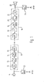
- the signals of a microphone 11 are usually fed to a PM transmitter 10 on the input side. These are amplified in an LF preamplifier 12 and fed to a frequency modulator 14 (FM modulator) via an evaluation network 13 (pre-emphasis, for example +6 dB / octave). Its output signals are fed to a UHF transmitter 15, from which they arrive as radio signals to a PM receiver. There they are fed via an UHF receiving part 17 to an intermediate frequency stage 18 (IF part), from where they then reach an FM demodulator 19. These signals are then fed via an evaluation network 20 (deemphasis, for example -6 dB / octave) to an LF amplifier 21, which makes them audible via a loudspeaker 22.
- the PM transmitters and PM receivers listed at the beginning as state of the art and commercially available are structured accordingly.
- a further evaluation network 23 is now connected upstream of the input of the PM transmitter 10, to which the AFSK signals are fed. These signals generated by frequency shift keying in the listening area work with, for example Frequencies 1200 and 1800 Hz.
- This evaluation network 23 is constructed with an opposite characteristic to the evaluation network 13 and is therefore implemented according to the described PM transmitter 10 as a deemphasis stage with -6 dB / octave. Accordingly, the output of the PM receiver 16 is connected to a further evaluation stage 24, which is implemented accordingly as a preemphasis stage with +6 dB / octave.
- the AFSK signals generated on the output side are then fed in an unshown manner to an AFSK demodulator and then, for example, to a printer, as described in more detail in the prior art specified at the outset.
- a first curve 25 in FIG. 2 shows the original spectrum of the AFSK source.
- the dash-dotted curve 26 shows the LF transmission characteristic of a PM transmitter. This transmission characteristic raises the higher tones by 6 dB / octave.
- Curve 27 shows the AFSK spectrum after evaluation by the PM characteristic of transmitter 10. Since the maximum permissible peak stroke Af max, which may be prescribed by law, for example, must not be exceeded, curve 27 represents the maximum transmission possibility with regard to an optimal one Signal-to-noise ratio if stages 23, 24 are initially ignored.
- the AFSK signals are first supplied to the deemphasis stage 23, which has an evaluation characteristic of -6 dB / octave, the AFSK spectrum is first evaluated according to curve 28 in FIG. 3. Due to the PM characteristic of the transmitter (+6 dB / octave), curve 28 is now at the level of Curve 29 raised. This represents an optimal transmission, since the maximum permissible peak travel is used over the entire frequency band.
- the proposed method is also suitable for improving the range of the 5-tone follow-up method or similar methods.
Abstract
Description
Die Erfindung geht aus von einem Verfahren nach der Gattung des Hauptanspruchs sowie einer Vorrichtung zur Durchführung des Verfahrens.The invention is based on a method according to the preamble of the main claim and an apparatus for carrying out the method.
Ein heute übliches Verfahren zur Funkübertragung von Sprache ist neben der frequenzmodulierten Übertragung (FM-Übertragung) die phasenmodulierte Übertragung (PM-übertragung). Die PM-Übertragung hat gegenüber der FM-Übertragung ein günstigeres Signal/ Rausch-Verhältnis. Sollen jedoch mit PM-Geräten kodierte Signale (AFSK-Signale) durch Frequenzumtastung im Hörbereich übertragen werden, wie dies aus der DE-OS 29 01 798 und der DE-OS 30 05 612 .bekannt ist und auch beispielsweise durch die handelsüblichen Funkgeräte KF 161 bis 163 (BOSCH) realisiert ist, so macht sich die NF-Übertragungscharakteristik eines PM-Senders ungünstig bemerkbar. Diese hebt nämlich die höheren Frequenzen um 6 dB/Oktave an, so daß eine Absenkung des Signalpegels vorgenommen werden muß, weil sonst der zulässige maximale Spitzenhub überschritten und das Modulationssignal verzerrt wird. Dadurch verschlechtert sich der Störabstand (Signal/ Rausch-Verhältnis) der AFSK-Übertragung mit PM-Geräten gegenüber FM-Geräten.In addition to frequency-modulated transmission (FM transmission), a common method for radio transmission of speech today is phase-modulated transmission (PM transmission). The PM transmission has a more favorable signal / noise ratio than the FM transmission. However, signals coded with PM devices (AFSK signals) are to be transmitted by frequency shift keying in the listening area, as is known from DE-OS 29 01 798 and DE-OS 30 05 612, and also, for example, from commercially available KF 161 radios up to 163 (BOSCH) is implemented, the AF transmission characteristics of a PM transmitter have an unfavorable effect. This increases the higher frequencies by 6 dB / octave, so that the signal level has to be reduced, because otherwise the permissible maximum peak deviation will be exceeded and the modulation signal will be distorted. As a result, the signal-to-noise ratio of the AFSK transmission with PM devices deteriorates compared to FM devices.
Das erfindungsgemäße Verfahren mit den kennzeichnenden Merkmalen des Hauptanspruchs hat demgegenüber den Vorteil, daß diese ungünstige NF-Übertragungscharakteristik des PM-Senders/Empfängers kompensiert wird, so daß über den ganzen Bereich mit dem maximal zulässigen Spitzenhub gesendet werden kann.The method according to the invention with the characterizing features of the main claim has the advantage that this unfavorable LF transmission characteristic of the PM transmitter / receiver is compensated so that transmission can take place over the entire range with the maximum permissible peak stroke.
Durch die in den Unteransprüchen aufgeführten Merkmale sind vorteilhafte Weiterbildungen und Verbesserungen des im Hauptanspruch angegebenen Verfahrens möglich.Advantageous further developments and improvements of the method specified in the main claim are possible due to the features listed in the subclaims.
Besonders vorteilhaft ist es, das zu übertragende AFSK-Signal vor der Zuführung in den PM-Sender mit einer entsprechenden gegenläufigen Charakteristik zu bewerten und am Ausgang des Empfängers dieses AFSK-Signal wieder abzugreifen und rückzubewerten. Dadurch können handelsübliche PM-Sender/Empfänger ohne Eingriffe in die Geräte selbst für die AFSK-Übertragung verwendet werden. An die entsprechenden Eingangs- und Ausgangsbuchsen müssen lediglich Zusatzgeräte angeschlossen werden. So können im gleichen Gerät neben der Sprechfunkübertragung in vorteilhafter Weise AFSK-Signale übertragen werden.It is particularly advantageous to evaluate the AFSK signal to be transmitted before it is fed into the PM transmitter with a corresponding opposite characteristic and to tap this AFSK signal again at the output of the receiver and to evaluate it again. As a result, commercially available PM transmitters / receivers can be used for AFSK transmission without interfering with the devices themselves. Only additional devices have to be connected to the corresponding input and output sockets. In this way, in addition to voice radio transmission, AFSK signals can advantageously be transmitted in the same device.
Diese Zusatzgeräte sind vorteilhaft Deemphasis-Stufen bzw. Preemphasis-Stufen, die dem Eingang des PM-Senders vorgeschaltet bzw. dem Ausgang des PM-Empfängers nachgeschaltet werden.These additional devices are advantageously de-emphasis stages or pre-emphasis stages, which are connected upstream of the input of the PM transmitter or downstream of the output of the PM receiver.
Ein Ausführungsbeispiel der Erfindung ist in der Zeichnung dargestellt und in der nachfolgenden Beschreibung näher erläutert.An embodiment of the invention is shown in the drawing and explained in more detail in the following description.
- Fig. 1 ein Ausführungsbeispiel der Erfindung im Blockschaltbild,1 shows an embodiment of the invention in a block diagram,
- Fig. 2 die Abhängigkeit des Frequenzhubes von der Modulationsfrequenz zur Erläuterung der Wirkungsweise der Übertragungsfunktion eines PM-Senders undFig. 2 shows the dependence of the frequency swing on the modulation frequency to explain the operation of the transfer function of a PM transmitter and
- Fig. 3 die Abhängigkeit des Frequenzhubes von der Modulationsfrequenz zur Erläuterung der Wirkungsweise der Kompensation.Fig. 3 shows the dependence of the frequency swing on the modulation frequency to explain the operation of the compensation.
Einem PM-Sender 10 werden gewöhnlich die Signale eines Mikrofons 11 eingangsseitig zugeführt. Diese werden in einem NF-Vorverstärker 12 verstärkt und über ein Bewertungsnetzwerk 13 (Preemphasis, zum Beispiel +6 dB/Oktave) einem Frequenzmodulator 14 (FM-Modulator) zugeführt. Dessen Ausgangssignale werden einem UHF-Sender 15 zugeleitet, von dem aus sie als Funksignale zu einem PM-Empfänger gelangen. Dort werden sie über ein UHF-Empfangsteil 17 einer Zwischenfrequenzstufe 18 (ZF-Teil) zugeführt, von wo aus sie dann zu einem FM-Demodulator 19 gelangen. Anschließend werden diese Signale dann über ein Bewertungsnetzwerk 20 (Deemphasis, zum Beispiel -6 dB/Oktave) einem NF-Verstärker 21 zugeführt, der sie über einen Lautsprecher 22 hörbar macht. Der eingangs als Stand der Technik angeführte und im Handel erhältliche PM-Sender und PM-Empfänger sind entsprechend aufgebaut.The signals of a
Dem Eingang des PM-Senders 10 ist nunmehr ein weiteres Bewertungsnetzwerk 23 vorgeschaltet, dem die AFSK-Signale zugeführt werden. Diese durch Frequenzumtastung im Hörbereich erzeugten Signale arbeiten beispielsweise mit den Frequenzen 1200 und 1800 Hz. Dieses Bewertungsnetzwerk 23 ist mit einer entgegengesetzten Charakteristik gegenüber dem Bewertungsnetzwerk 13 aufgebaut und ist daher gemäß dem beschriebenen PM-Sender 10 als Deemphasis-Stufe mit -6 dB/Oktave realisiert. Entsprechend ist der Ausgang des PM-Empfängers 16 mit einer weiteren Bewertungsstufe 24 verbunden, die entsprechend als Preemphasis-Stufe mit +6 dB/Oktave realisiert ist. Die ausgangsseitig erzeugten AFSK-Signale werden in nicht näher dargestellter Weise dann einem AFSK-Demodulator und anschließend beispielsweise einem Drucker zugeführt, wie dies im eingangs angegebenen Stand der Technik näher beschrieben ist.A
Die Wirkungsweise des in Fig. 1 dargestellten Ausführungsbeispiels soll im folgenden anhand der in den Fig. 2 und 3 dargestellten Schemata erläutert werden. Eine erste Kurve 25 in Fig. 2 zeigt das Ursprungsspektrum der AFSK-Quelle. Die strichpunktierte Kurve 26 zeigt die NF-Übertragungscharakteristik eines PM-Senders. Durch diese Übertragungscharakteristik werden die höheren Töne um 6 dB/Oktave angehoben. Die Kurve 27 zeigt das AFSK-Spektrum nach der Bewertung durch die PM-Charakteristik des Senders 10. Da der maximal zulässige Spitzenhub Af max der zum Beispiel gesetzlich vorgeschrieben sein kann, nicht überschritten werden darf, stellt die Kurve 27 die maximale Übertragungsmöglichkeit bezüglich eines optimalen Störabstandes dar, wenn zunächst die Stufen 23, 24 unberücksichtigt bleiben.The mode of operation of the exemplary embodiment shown in FIG. 1 will be explained below with reference to the diagrams shown in FIGS. 2 and 3. A
Da gemäß dem Ausführungsbeispiel jedoch die AFSK-Signale zunächst der Deemphasis-Stufe 23 zugeführt werden, die eine Bewertungscharakteristik von -6 dB/Oktave aufweist, wird das AFSK-Spektrum zunächst gemäß der Kurve 28 in Fig. 3 bewertet. Durch die PM-Charakteristik des Senders (+6 dB/Oktave) wird nun die Kurve 28 auf das Niveau der Kurve 29 angehoben. Dies stellt eine optimale Übertragung dar, da über das ganze Frequenzband mit dem maximal zulässigen Spitzenhub gearbeitet wird.However, since according to the exemplary embodiment the AFSK signals are first supplied to the
Im Empfänger 16 laufen dann natürlich die umgekehrten Vorgänge ab, das heißt, im Bewertungsnetzwerk 20 wird aus dem Spektrum 29 wieder das Spektrum 28 und im Bewertungsnetzwerk 24 daraus wieder das Spektrum 25, das dem ursprünglich eingegebenen AFSK-Spektrum entspricht. Damit ist eine lineare Übertragung dieses Signals bei maximal möglichem Spitzenhub erreicht. Der Störabstand ist gegenüber handelsüblichen Funkgeräten um 4,4 dB verbessert worden.The reverse processes then naturally take place in the
Es sei noch erwähnt, daß das vorgeschlagene Verfahren auch zur Reichweite-Verbesserung des 5-Ton-Folgeverfahrens oder ähnlicher Verfahren geeignet ist.It should also be mentioned that the proposed method is also suitable for improving the range of the 5-tone follow-up method or similar methods.
Claims (5)
Priority Applications (1)
| Application Number | Priority Date | Filing Date | Title |
|---|---|---|---|
| AT82109125T ATE32405T1 (en) | 1982-02-20 | 1982-10-02 | METHOD AND DEVICE FOR TRANSMISSION OF SIGNALS CODED BY FREQUENCY SHIFT KEYING IN THE LISTENING RANGE. |
Applications Claiming Priority (2)
| Application Number | Priority Date | Filing Date | Title |
|---|---|---|---|
| DE19823206132 DE3206132A1 (en) | 1982-02-20 | 1982-02-20 | METHOD AND DEVICE FOR TRANSMITTING SIGNALS ENCODED BY FREQUENCY KEY CHANGING (AFSK SIGNALS) |
| DE3206132 | 1982-02-20 |
Publications (3)
| Publication Number | Publication Date |
|---|---|
| EP0086872A2 true EP0086872A2 (en) | 1983-08-31 |
| EP0086872A3 EP0086872A3 (en) | 1984-09-12 |
| EP0086872B1 EP0086872B1 (en) | 1988-02-03 |
Family
ID=6156255
Family Applications (1)
| Application Number | Title | Priority Date | Filing Date |
|---|---|---|---|
| EP82109125A Expired EP0086872B1 (en) | 1982-02-20 | 1982-10-02 | Method and device for transmitting signals which are frequency-shift-keyed in the audible field |
Country Status (3)
| Country | Link |
|---|---|
| EP (1) | EP0086872B1 (en) |
| AT (1) | ATE32405T1 (en) |
| DE (2) | DE3206132A1 (en) |
Citations (3)
| Publication number | Priority date | Publication date | Assignee | Title |
|---|---|---|---|---|
| GB1170432A (en) * | 1965-11-08 | 1969-11-12 | Nippon Electric Co | Improvements in or relating to Electrical Phase Modulation Transmission Systems |
| GB1230217A (en) * | 1967-09-28 | 1971-04-28 | ||
| US4053834A (en) * | 1973-04-12 | 1977-10-11 | Textron, Inc. | Narrowband phase modulation communication system which eliminates thresholding |
-
1982
- 1982-02-20 DE DE19823206132 patent/DE3206132A1/en not_active Withdrawn
- 1982-10-02 EP EP82109125A patent/EP0086872B1/en not_active Expired
- 1982-10-02 DE DE8282109125T patent/DE3278097D1/en not_active Expired
- 1982-10-02 AT AT82109125T patent/ATE32405T1/en not_active IP Right Cessation
Patent Citations (3)
| Publication number | Priority date | Publication date | Assignee | Title |
|---|---|---|---|---|
| GB1170432A (en) * | 1965-11-08 | 1969-11-12 | Nippon Electric Co | Improvements in or relating to Electrical Phase Modulation Transmission Systems |
| GB1230217A (en) * | 1967-09-28 | 1971-04-28 | ||
| US4053834A (en) * | 1973-04-12 | 1977-10-11 | Textron, Inc. | Narrowband phase modulation communication system which eliminates thresholding |
Non-Patent Citations (2)
| Title |
|---|
| FUNKSCHAU, Band 52, Nr. 17, 14. August 1980, Seiten 67-71, M}nchen, DE B. WIEDENROTH: "High-Com-]berblick und Entwicklungsstand" * |
| INTERNATIONAL CONFERENCE ON COMMUNICATIONS, Denver, Colorado, 14.-18. Juni 1981, Conference Record, Band 2, Seiten 23.1.1 - 23.1.4, New York, USA P. CONSTANTINOU et al.: "Digital transmission over conventional mobile channels maximum bit rate" * |
Also Published As
| Publication number | Publication date |
|---|---|
| ATE32405T1 (en) | 1988-02-15 |
| DE3278097D1 (en) | 1988-03-10 |
| EP0086872B1 (en) | 1988-02-03 |
| EP0086872A3 (en) | 1984-09-12 |
| DE3206132A1 (en) | 1983-09-01 |
Similar Documents
| Publication | Publication Date | Title |
|---|---|---|
| DE2401186C2 (en) | Microwave relay system with auxiliary signal transmission | |
| DE1803539B2 (en) | 30.0 ^ .6S "37420 8/8/68" 56894 TV Telephony Facility | |
| DE2701814C3 (en) | Electric channel vocoder | |
| DE1512251C3 (en) | Transmission system for binary data with frequency modulation and residual sideband operation | |
| CH436402A (en) | Single sideband transmission device for the transmission of amplitude-modulated vibrations | |
| DE3311646C2 (en) | ||
| EP0086872B1 (en) | Method and device for transmitting signals which are frequency-shift-keyed in the audible field | |
| DE815356C (en) | Intercom | |
| DE3008529C2 (en) | ||
| DE4128045A1 (en) | Noise suppression for stereo radio - compresses lower and upper side bands of differential signal in stereo transmitter | |
| DE1951224A1 (en) | Telecommunication system with frequency modulation | |
| DE2210147B2 (en) | Transmission of test frequency with main sound program - by maintaining ratio of test signal to program level approximately constant to reduce interference | |
| DE4240609C2 (en) | Frequency response correction method | |
| DE911146C (en) | Device for multiple telephony and character transmission in two-way communication on short waves | |
| DE2241077C3 (en) | Method for the transmission of tone sequence selective call signals via narrowband telegraphic channels on shortwave radio links | |
| AT233057B (en) | Transmission device for the transmission of amplitude-modulated vibrations | |
| DE1537637C3 (en) | System for signal transmission as well as applicable transmitters and receivers | |
| DE884520C (en) | Radiotelephone with two-way communication | |
| DE2528455A1 (en) | Stereophonic program signals transmission system - using auxiliary carrier transmits signals over HF FM channel with difference modulation | |
| DE2318227C3 (en) | Device for the disguised transmission of speech signals | |
| DE1215223B (en) | Arrangement for transmission of a frequency-modulated wave | |
| DE1015503B (en) | Method for the transmission of signals by double modulating a carrier wave in frequency and amplitude | |
| DE2928816A1 (en) | Automatic volume control of road vehicle radio - has microphone, in passenger compartment to detect ambient level, operating with subtractor to control volume | |
| DE2241077B2 (en) | METHOD FOR TRANSMISSION OF TONE SEQUENCE SELECTIVE CALL SIGNALS VIA NARROW-BAND TELEGRAPHY CHANNELS ON SHORTWAVE RADIO CONNECTIONS | |
| DE3337357A1 (en) | Method for transmitting speech and information signals |
Legal Events
| Date | Code | Title | Description |
|---|---|---|---|
| PUAI | Public reference made under article 153(3) epc to a published international application that has entered the european phase |
Free format text: ORIGINAL CODE: 0009012 |
|
| AK | Designated contracting states |
Designated state(s): AT BE DE FR GB IT NL |
|
| PUAL | Search report despatched |
Free format text: ORIGINAL CODE: 0009013 |
|
| AK | Designated contracting states |
Designated state(s): AT BE DE FR GB IT NL |
|
| 17P | Request for examination filed |
Effective date: 19850123 |
|
| GRAA | (expected) grant |
Free format text: ORIGINAL CODE: 0009210 |
|
| AK | Designated contracting states |
Kind code of ref document: B1 Designated state(s): AT BE DE FR GB IT NL |
|
| REF | Corresponds to: |
Ref document number: 32405 Country of ref document: AT Date of ref document: 19880215 Kind code of ref document: T |
|
| REF | Corresponds to: |
Ref document number: 3278097 Country of ref document: DE Date of ref document: 19880310 |
|
| ET | Fr: translation filed | ||
| ITF | It: translation for a ep patent filed |
Owner name: BARZANO' E ZANARDO ROMA S.P.A. |
|
| GBT | Gb: translation of ep patent filed (gb section 77(6)(a)/1977) | ||
| PGFP | Annual fee paid to national office [announced via postgrant information from national office to epo] |
Ref country code: DE Payment date: 19881018 Year of fee payment: 7 |
|
| PLBE | No opposition filed within time limit |
Free format text: ORIGINAL CODE: 0009261 |
|
| STAA | Information on the status of an ep patent application or granted ep patent |
Free format text: STATUS: NO OPPOSITION FILED WITHIN TIME LIMIT |
|
| 26N | No opposition filed | ||
| PGFP | Annual fee paid to national office [announced via postgrant information from national office to epo] |
Ref country code: GB Payment date: 19890930 Year of fee payment: 8 |
|
| PGFP | Annual fee paid to national office [announced via postgrant information from national office to epo] |
Ref country code: AT Payment date: 19891002 Year of fee payment: 8 |
|
| ITTA | It: last paid annual fee | ||
| PG25 | Lapsed in a contracting state [announced via postgrant information from national office to epo] |
Ref country code: BE Effective date: 19891031 |
|
| BERE | Be: lapsed |
Owner name: ROBERT BOSCH G.M.B.H. Effective date: 19891031 |
|
| PG25 | Lapsed in a contracting state [announced via postgrant information from national office to epo] |
Ref country code: NL Effective date: 19900501 |
|
| NLV4 | Nl: lapsed or anulled due to non-payment of the annual fee | ||
| PG25 | Lapsed in a contracting state [announced via postgrant information from national office to epo] |
Ref country code: FR Effective date: 19900629 |
|
| PG25 | Lapsed in a contracting state [announced via postgrant information from national office to epo] |
Ref country code: DE Effective date: 19900703 |
|
| REG | Reference to a national code |
Ref country code: FR Ref legal event code: ST |
|
| PG25 | Lapsed in a contracting state [announced via postgrant information from national office to epo] |
Ref country code: GB Effective date: 19901002 Ref country code: AT Effective date: 19901002 |
|
| GBPC | Gb: european patent ceased through non-payment of renewal fee |