EP0086728A2 - Vorrichtung für das Ein-und/oder-Ausschleusen von Feststoffen durch mindestens eine Öffnung einer Behandlungskammer, insbesondere unter vermindertem Druck - Google Patents
Vorrichtung für das Ein-und/oder-Ausschleusen von Feststoffen durch mindestens eine Öffnung einer Behandlungskammer, insbesondere unter vermindertem Druck Download PDFInfo
- Publication number
- EP0086728A2 EP0086728A2 EP83420018A EP83420018A EP0086728A2 EP 0086728 A2 EP0086728 A2 EP 0086728A2 EP 83420018 A EP83420018 A EP 83420018A EP 83420018 A EP83420018 A EP 83420018A EP 0086728 A2 EP0086728 A2 EP 0086728A2
- Authority
- EP
- European Patent Office
- Prior art keywords
- sheath
- venturi tube
- pressure
- convergent
- section
- Prior art date
- Legal status (The legal status is an assumption and is not a legal conclusion. Google has not performed a legal analysis and makes no representation as to the accuracy of the status listed.)
- Granted
Links
- 239000007787 solid Substances 0.000 claims abstract description 22
- 239000012530 fluid Substances 0.000 claims abstract description 19
- 230000008859 change Effects 0.000 claims abstract description 11
- 238000011282 treatment Methods 0.000 claims description 23
- 238000004891 communication Methods 0.000 claims description 8
- 230000000712 assembly Effects 0.000 claims description 7
- 238000000429 assembly Methods 0.000 claims description 7
- 239000000126 substance Substances 0.000 claims description 6
- 238000002347 injection Methods 0.000 claims description 3
- 239000007924 injection Substances 0.000 claims description 3
- 238000006243 chemical reaction Methods 0.000 claims description 2
- 230000000694 effects Effects 0.000 claims description 2
- 238000005086 pumping Methods 0.000 claims description 2
- 238000011144 upstream manufacturing Methods 0.000 claims description 2
- 239000000047 product Substances 0.000 description 12
- 239000011554 ferrofluid Substances 0.000 description 3
- XEEYBQQBJWHFJM-UHFFFAOYSA-N Iron Chemical compound [Fe] XEEYBQQBJWHFJM-UHFFFAOYSA-N 0.000 description 2
- 238000009434 installation Methods 0.000 description 2
- 238000000034 method Methods 0.000 description 2
- 229920006395 saturated elastomer Polymers 0.000 description 2
- 239000012265 solid product Substances 0.000 description 2
- 210000005070 sphincter Anatomy 0.000 description 2
- 238000004381 surface treatment Methods 0.000 description 2
- 241000287107 Passer Species 0.000 description 1
- NRTOMJZYCJJWKI-UHFFFAOYSA-N Titanium nitride Chemical compound [Ti]#N NRTOMJZYCJJWKI-UHFFFAOYSA-N 0.000 description 1
- 230000009471 action Effects 0.000 description 1
- 230000002411 adverse Effects 0.000 description 1
- 238000013019 agitation Methods 0.000 description 1
- 238000001816 cooling Methods 0.000 description 1
- 230000008878 coupling Effects 0.000 description 1
- 238000010168 coupling process Methods 0.000 description 1
- 238000005859 coupling reaction Methods 0.000 description 1
- 238000007872 degassing Methods 0.000 description 1
- 238000005238 degreasing Methods 0.000 description 1
- 230000008021 deposition Effects 0.000 description 1
- 238000001035 drying Methods 0.000 description 1
- 239000012535 impurity Substances 0.000 description 1
- 229910052742 iron Inorganic materials 0.000 description 1
- 239000007788 liquid Substances 0.000 description 1
- 230000005389 magnetism Effects 0.000 description 1
- 238000005554 pickling Methods 0.000 description 1
- 230000008569 process Effects 0.000 description 1
- 238000007790 scraping Methods 0.000 description 1
- 230000035939 shock Effects 0.000 description 1
- 238000005507 spraying Methods 0.000 description 1
- 238000009489 vacuum treatment Methods 0.000 description 1
- 239000012808 vapor phase Substances 0.000 description 1
- XLYOFNOQVPJJNP-UHFFFAOYSA-N water Substances O XLYOFNOQVPJJNP-UHFFFAOYSA-N 0.000 description 1
Images

Classifications
-
- C—CHEMISTRY; METALLURGY
- C23—COATING METALLIC MATERIAL; COATING MATERIAL WITH METALLIC MATERIAL; CHEMICAL SURFACE TREATMENT; DIFFUSION TREATMENT OF METALLIC MATERIAL; COATING BY VACUUM EVAPORATION, BY SPUTTERING, BY ION IMPLANTATION OR BY CHEMICAL VAPOUR DEPOSITION, IN GENERAL; INHIBITING CORROSION OF METALLIC MATERIAL OR INCRUSTATION IN GENERAL
- C23C—COATING METALLIC MATERIAL; COATING MATERIAL WITH METALLIC MATERIAL; SURFACE TREATMENT OF METALLIC MATERIAL BY DIFFUSION INTO THE SURFACE, BY CHEMICAL CONVERSION OR SUBSTITUTION; COATING BY VACUUM EVAPORATION, BY SPUTTERING, BY ION IMPLANTATION OR BY CHEMICAL VAPOUR DEPOSITION, IN GENERAL
- C23C14/00—Coating by vacuum evaporation, by sputtering or by ion implantation of the coating forming material
- C23C14/22—Coating by vacuum evaporation, by sputtering or by ion implantation of the coating forming material characterised by the process of coating
- C23C14/56—Apparatus specially adapted for continuous coating; Arrangements for maintaining the vacuum, e.g. vacuum locks
- C23C14/562—Apparatus specially adapted for continuous coating; Arrangements for maintaining the vacuum, e.g. vacuum locks for coating elongated substrates
-
- D—TEXTILES; PAPER
- D06—TREATMENT OF TEXTILES OR THE LIKE; LAUNDERING; FLEXIBLE MATERIALS NOT OTHERWISE PROVIDED FOR
- D06B—TREATING TEXTILE MATERIALS USING LIQUIDS, GASES OR VAPOURS
- D06B23/00—Component parts, details, or accessories of apparatus or machines, specially adapted for the treating of textile materials, not restricted to a particular kind of apparatus, provided for in groups D06B1/00 - D06B21/00
- D06B23/14—Containers, e.g. vats
- D06B23/18—Sealing arrangements
-
- F—MECHANICAL ENGINEERING; LIGHTING; HEATING; WEAPONS; BLASTING
- F16—ENGINEERING ELEMENTS AND UNITS; GENERAL MEASURES FOR PRODUCING AND MAINTAINING EFFECTIVE FUNCTIONING OF MACHINES OR INSTALLATIONS; THERMAL INSULATION IN GENERAL
- F16J—PISTONS; CYLINDERS; SEALINGS
- F16J15/00—Sealings
- F16J15/16—Sealings between relatively-moving surfaces
- F16J15/168—Sealings between relatively-moving surfaces which permits material to be continuously conveyed
Definitions
- the invention relates to a device for the introduction and / or removal, in a sealed manner, of solids through at least one orifice of a treatment enclosure, low-pressure tank or the like, the pressure of which is less than that of the immediate environment.
- vacuum processing machines are discontinuous. Generally, they have a series of chambers in which different heights of vacuum can prevail, said chambers being capable of successively pickling, treating, drying, cooling, etc.
- Each successive operation is characterized by the simultaneous opening a set of valves which separate the enclosures two by two, and by an advance of the entire treatment chain, equal to the modular length of an enclosure. After each valve closure, the vacuum pump assemblies come into action to restore the desired pressure.
- the present invention aims to remedy these drawbacks.
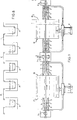
- the invention as characterized in the claims solves the problem of creating a device comprising a venturi tube internally and successively constituting a convergent, a neck and a divergent, said tube being connected, on the convergent side, to a sleeve arranged and equipped to allow the injection of a pressurized fluid and its flow towards the interior of the venturi tube; said sleeve, capable of being coupled to the enclosure, low-pressure tank or the like, having internally, directly or in an attached manner, an axial sheath for introduction and communication between the orifice of said enclosure or the like and the venturi tube; said sheath cooperates with the convergent of the venturi tube, substantially up to the level of the neck, so as to create, at this level, an abrupt change of section which has the effect of defining a dynamic joint zone in combination with the pressures of the fluid , the solid or solids being capable of being introduced on the side of the divergent to be engaged without friction in the bore of the communication sleeve, with
- a convergent (a) which serves to set the fluid in motion, transforms the pressure energy of said fluid into kinetic energy.
- part II which corresponds to a neck (b)
- the abrupt change of section takes place: the fluid, initially in the section (SO) at speed (VO) and at pressure (PO), suddenly passes through a section (S1) at a speed (V1) and at a pressure (P1) very substantially zero.
- a divergent (c) transforms kinetic energy into potential pressure energy. From section (S2) to section (S3), at the outlet of the divergent (c), the fluid changes from speed (V2) to speed (V3) and from pressure (P2) to pressure (P3) substantially corresponding to atmospheric pressure.
- the sudden change of section can be made either at the connection part of the convergent (a) and the neck (b), ( Figure 1), or upstream of the neck (b), ( Figure 2) , or over part of the length of the neck (b), Figure 3.
- the sudden change of section is not caused in the divergence (c), as this would adversely affect the yield.
- a zone (Z) corresponding to a dynamic joint zone At the level of this sudden change of section, there occurs, in combination with the fluid flow, a zone (Z) corresponding to a dynamic joint zone.
- This physical phenomenon is particularly important and advantageous for circulating a solid product (a wire for example) from any place at a pressure (P3) in, for example, an enclosure whose pressure (Po) is lower and this with a stable and complete seal in between.
- FIG. 4 shows a non-limiting example of embodiment of the device which implements the fundamental principles set out above.
- the device essentially comprises a venturi tube (1) which internally and successively constitutes the convergent (a), the neck (b) and the divergent (c).
- This venturi tube (1) is integral, in a removable manner or not, on the converging side (a), with a coupling sleeve (2) shaped externally at (2a) to allow the injection of a pressurized fluid and its laminar flow towards the venturi (1).
- the sleeve (2) has internally, directly or in an attached manner, an axial sheath (2b) for communication between the Venturi tube (1) and for example, an enclosure (3) to which the sleeve (2).
- the sheath (2b) cooperates with the convergent (a), at the neck (b), as indicated above, so as to create at this level, the sudden change of section. This therefore results in the dynamic joint zone (Z).
- the outer section (S) of the end of the sheath (2), at the neck (b) as well as the section (S ') of said neck (b), in line with the end of the sheath, must be suitably sized in combination with the section (s) of the solid to be introduced ( Figure 5).
- the efficiency of the system (S and S ') i.e. Without the solid
- the efficiency of the system (S and (S' - s) must be the same as the efficiency of the system (S and (S' - s)) so that the ratios SS 'and are equivalent in order to lead to the same pressure jump coefficient during energy conversion. We thus set a minimum of performance whatever the conditions.
- the device is particularly well suited for bringing in and / or leaving, in a completely sealed manner, solids through an orifice (o) of a treatment enclosure (3) whose pressure (Po) is lower. to that of the immediate environment (P3) which can be another enclosure or atmospheric pressure.
- the solid (s), for example wires, are capable of being introduced on the side of the divergent (c), that is to say at the pressure level (P3), to be engaged without friction in the bore of the sleeve (2), in order to be introduced through the orifice (o) in the enclosure (3) at the pressure (Po) to undergo various treatments according to the specific applications sought.
- the dynamic joint zone created allows the enclosure (3) to be polluted neither by the device, nor by the environment.
- the device (D) can for example be mounted as indicated, on one side of the enclosure (3) (FIG. 6), the solids being introduced (manually, automatically or by any means appropriate), on the same side of the divergent (C).
- the enclosure can be equipped with two devices in accordance with the invention and situated on the same axial alignment (FIG. 7), one of the devices corresponding to the input of these solids; the other, at the exit.
- the sleeve (2), opposite the divergent (c), is always located on the low pressure side (enclosure for example). It is obvious that according to the laws of fluid dynamics, the different parameters are calculated so that there is no possible path of the fluid from the outside to the inside of the enclosure.
- This injected fluid can be water, oil or other ...
- the sleeve (2) can have various internal arrangements, for example, to make the communication sheath adjustable in linear position, to allow the guidance of solids, etc.
- the invention finds particularly advantageous applications for vacuum treatments, as well as for chemical or electrochemical surface treatments of elongated solids such as: wires, profiles, sheets, etc.
- the device provides very important advantages compared to the known techniques currently used.
- the wire to be treated (F) had to follow a special path to pass from one tank (A) to another, in order to undergo the various treatments required (degreasing, pre-rinsing, rinsing, depassivation, galvanic deposition ).
- the device according to the invention makes it possible in particular to eliminate this complex path of the wire and to increase the treatment in a relatively significant way, since according to the prior art, by way of indication, we were able to process very substantially under 1A / dm2 , while the application of the device with very intense agitation, makes it possible to reach 5 to 10A / dm2.
- FIG. 9 shows, by way of nonlimiting example, an installation for the application of the device to a chemical or electrochemical treatment.
- the installation obviously includes several treatment tanks designated as a whole by (B).
- the device (D) connected on the converging side, to a low pressure enclosure (E) whose calibrated inlet orifice acts as a pressure drop.
- a low pressure enclosure E
- two sets of venturi tubes (1) - sheath (2) the convergers of each of said sets being coupled by a common low-pressure chamber (E1).
- the low pressure chamber (E1) can be fitted with a valve plug and with a means for controlling leaks to balance the vapor pressures.
- the last tank (B2) at its exit, in the same way as the first tank (B1) at its entry, is equipped with a venturi tube (1) - sheath (2) assembly, the convergent of which is connected to an enclosure low pressure (E2).
- the convergers of each of the Venturi (1) - sheath (2) assemblies are suitably coupled to pumping means (P) relating to each of the corresponding tanks,
- the wire or other solid to be treated can therefore be introduced, treated and removed from the first to the last tank, in a completely linear manner, in opposition to known systems.
- This association can be made either by combining .n devices mounted in series, or by n groups of two devices mounted in opposition.
Landscapes
- Engineering & Computer Science (AREA)
- Chemical & Material Sciences (AREA)
- General Engineering & Computer Science (AREA)
- Mechanical Engineering (AREA)
- Textile Engineering (AREA)
- Materials Engineering (AREA)
- Metallurgy (AREA)
- Organic Chemistry (AREA)
- Chemical Kinetics & Catalysis (AREA)
- Physical Or Chemical Processes And Apparatus (AREA)
- Treatment Of Fiber Materials (AREA)
- Physical Vapour Deposition (AREA)
- Electroplating Methods And Accessories (AREA)
- Catching Or Destruction (AREA)
- Printers Or Recording Devices Using Electromagnetic And Radiation Means (AREA)
- Electrical Discharge Machining, Electrochemical Machining, And Combined Machining (AREA)
Priority Applications (1)
| Application Number | Priority Date | Filing Date | Title |
|---|---|---|---|
| AT83420018T ATE34816T1 (de) | 1982-02-11 | 1983-02-03 | Vorrichtung fuer das ein-und/oder-ausschleusen von feststoffen durch mindestens eine oeffnung einer behandlungskammer, insbesondere unter vermindertem druck. |
Applications Claiming Priority (2)
| Application Number | Priority Date | Filing Date | Title |
|---|---|---|---|
| FR8202717 | 1982-02-11 | ||
| FR8202717A FR2521044A1 (fr) | 1982-02-11 | 1982-02-11 | Dispositif pour l'introduction et/ou le retrait d'une maniere etanche, de solides a travers au moins un orifice d'une enceinte de traitement a basse pression notamment |
Publications (3)
| Publication Number | Publication Date |
|---|---|
| EP0086728A2 true EP0086728A2 (de) | 1983-08-24 |
| EP0086728A3 EP0086728A3 (en) | 1984-06-06 |
| EP0086728B1 EP0086728B1 (de) | 1988-06-01 |
Family
ID=9271125
Family Applications (1)
| Application Number | Title | Priority Date | Filing Date |
|---|---|---|---|
| EP83420018A Expired EP0086728B1 (de) | 1982-02-11 | 1983-02-03 | Vorrichtung für das Ein-und/oder-Ausschleusen von Feststoffen durch mindestens eine Öffnung einer Behandlungskammer, insbesondere unter vermindertem Druck |
Country Status (7)
| Country | Link |
|---|---|
| US (1) | US4494478A (de) |
| EP (1) | EP0086728B1 (de) |
| JP (1) | JPS58157967A (de) |
| AT (1) | ATE34816T1 (de) |
| DE (2) | DE86728T1 (de) |
| ES (1) | ES8400684A1 (de) |
| FR (1) | FR2521044A1 (de) |
Cited By (3)
| Publication number | Priority date | Publication date | Assignee | Title |
|---|---|---|---|---|
| GB2189843A (en) * | 1986-04-30 | 1987-11-04 | James Maitland Pringle | Apparatus for mixing fluids |
| EP0243628A3 (en) * | 1986-03-22 | 1988-10-26 | Bayer Ag | Sealing for apparatus with continuous product transport sealing for apparatus with continuous product transport |
| EP0655519A1 (de) * | 1993-11-30 | 1995-05-31 | DANIELI & C. OFFICINE MECCANICHE S.p.A. | Hydrodynamische Dichtungs- und hydrostatische Trägerplatte für Beiz- und/oder chemischen Behandlungs- und/oder Reinigungsanlagen von metallischen Bandern |
Families Citing this family (4)
| Publication number | Priority date | Publication date | Assignee | Title |
|---|---|---|---|---|
| JPS61204386A (ja) * | 1985-03-06 | 1986-09-10 | Naniwa Seitei Kk | 表面処理方法とその装置 |
| GB9522062D0 (en) * | 1995-10-27 | 1996-01-03 | Rolls Royce Plc | A seal and a chamber having a seal |
| FR2940923B1 (fr) * | 2009-01-13 | 2012-02-24 | Gloster Europe | Appareil de brumisation a injecteur a fractionnement |
| CN113294524A (zh) * | 2021-05-21 | 2021-08-24 | 北京卫蓝新能源科技有限公司 | 一种非接触式密封结构 |
Family Cites Families (7)
| Publication number | Priority date | Publication date | Assignee | Title |
|---|---|---|---|---|
| US2509699A (en) * | 1947-10-30 | 1950-05-30 | Western Electric Co | Apparatus for continuously making vulcanized articles |
| US2661619A (en) * | 1950-01-17 | 1953-12-08 | Chemstrand Corp | Apparatus for the fluid treatment of fibers and the like |
| US2853970A (en) * | 1956-03-09 | 1958-09-30 | Ohio Commw Eng Co | Continuous gas plating apparatus under vacuum seal |
| US3055080A (en) * | 1960-07-19 | 1962-09-25 | Du Pont | Apparatus for fluid treatment of tow and yarn bundles |
| US3240037A (en) * | 1963-10-03 | 1966-03-15 | Monsanto Co | Continuous annealer |
| US3868104A (en) * | 1973-07-26 | 1975-02-25 | Little Inc A | Contactless fluid seal |
| US3952568A (en) * | 1974-09-04 | 1976-04-27 | The Electricity Council | Vacuum processing of rod, wire or strip material |
-
1982
- 1982-02-11 FR FR8202717A patent/FR2521044A1/fr active Granted
-
1983
- 1983-02-03 DE DE198383420018T patent/DE86728T1/de active Pending
- 1983-02-03 AT AT83420018T patent/ATE34816T1/de not_active IP Right Cessation
- 1983-02-03 DE DE8383420018T patent/DE3376868D1/de not_active Expired
- 1983-02-03 EP EP83420018A patent/EP0086728B1/de not_active Expired
- 1983-02-09 JP JP58020520A patent/JPS58157967A/ja active Granted
- 1983-02-10 US US06/465,503 patent/US4494478A/en not_active Expired - Fee Related
- 1983-02-10 ES ES519683A patent/ES8400684A1/es not_active Expired
Cited By (4)
| Publication number | Priority date | Publication date | Assignee | Title |
|---|---|---|---|---|
| EP0243628A3 (en) * | 1986-03-22 | 1988-10-26 | Bayer Ag | Sealing for apparatus with continuous product transport sealing for apparatus with continuous product transport |
| GB2189843A (en) * | 1986-04-30 | 1987-11-04 | James Maitland Pringle | Apparatus for mixing fluids |
| GB2189843B (en) * | 1986-04-30 | 1989-11-29 | James Maitland Pringle | Apparatus for mixing fluids |
| EP0655519A1 (de) * | 1993-11-30 | 1995-05-31 | DANIELI & C. OFFICINE MECCANICHE S.p.A. | Hydrodynamische Dichtungs- und hydrostatische Trägerplatte für Beiz- und/oder chemischen Behandlungs- und/oder Reinigungsanlagen von metallischen Bandern |
Also Published As
| Publication number | Publication date |
|---|---|
| EP0086728A3 (en) | 1984-06-06 |
| ATE34816T1 (de) | 1988-06-15 |
| FR2521044B1 (de) | 1984-04-13 |
| JPS58157967A (ja) | 1983-09-20 |
| ES519683A0 (es) | 1983-11-16 |
| US4494478A (en) | 1985-01-22 |
| DE86728T1 (de) | 1985-06-05 |
| ES8400684A1 (es) | 1983-11-16 |
| JPH0245703B2 (de) | 1990-10-11 |
| EP0086728B1 (de) | 1988-06-01 |
| FR2521044A1 (fr) | 1983-08-12 |
| DE3376868D1 (en) | 1988-07-07 |
Similar Documents
| Publication | Publication Date | Title |
|---|---|---|
| EP0086728B1 (de) | Vorrichtung für das Ein-und/oder-Ausschleusen von Feststoffen durch mindestens eine Öffnung einer Behandlungskammer, insbesondere unter vermindertem Druck | |
| FR2486422A1 (fr) | Ensemble formant cabine et vaporisation pour le lavage ou le traitement chimique d'objets d'une sorte souhaitee | |
| FR2575792A1 (fr) | Amplificateur de pression hydraulique | |
| FR2675234A1 (fr) | Manchon anticorrosion pour un percage pratique dans un tuyau en metal, et outil pour le montage de ce manchon. | |
| WO2004004086A1 (fr) | Furet d'installation d'un cable dans un conduit | |
| FR2793081A1 (fr) | Dispositif d'etancheite du type presse-garniture pour un cable | |
| EP2836697A1 (de) | Kraftstoffeinspritzleiste für einen verbrennungsmotor | |
| FR2541390A1 (fr) | Ejecteur-melangeur a effet de trompe, utilise notamment comme thermocompresseur | |
| FR2489439A1 (fr) | Tube de decharge de fluide ameliore | |
| FR2558735A1 (fr) | Cryopiege | |
| EP0267080A1 (de) | Vorrichtung zum Abschrecken der Innen- und Aussenseiten von röhrenförmigen Gegenständen | |
| FR2925111A3 (fr) | Pot catalytique et vehicule automobile comportant un tel pot catalytique | |
| EP0020246A1 (de) | Vorrichtung zum Kühlen langer laminierter Wärmwalzprodukte | |
| FR2786335A1 (fr) | Generateur, notamment alternateur pour vehicule automobile, a refroidissement par liquide | |
| CH371934A (fr) | Robinet de détente d'un fluide gazeux compressé | |
| FR2843052A1 (fr) | Installation de peinture nettoyee par ecouvillon | |
| EP0032093B1 (de) | Kühlvorrichtung für lange Produkte während des Durchlaufs | |
| BE1000264A6 (fr) | Rampe de pulverisation et ajutage pour fluide sous pression utilises a cet effet. | |
| FR2535409A1 (fr) | Amortisseur phonique et hydrodynamique | |
| FR2850139A1 (fr) | Accessoire pour dispositif de decharge brusque d'air et dispositif de decharge equipe de cet accessoire | |
| CH657670A5 (en) | Fluid pump | |
| FR2369613A1 (fr) | Valve perfectionnee de reglage de debit | |
| BE648762A (de) | ||
| EP0859150A1 (de) | Oszillierende Kolbenpumpe | |
| CH105310A (fr) | Pompe à liquide. |
Legal Events
| Date | Code | Title | Description |
|---|---|---|---|
| PUAI | Public reference made under article 153(3) epc to a published international application that has entered the european phase |
Free format text: ORIGINAL CODE: 0009012 |
|
| AK | Designated contracting states |
Designated state(s): AT BE CH DE GB IT LI LU NL SE |
|
| PUAL | Search report despatched |
Free format text: ORIGINAL CODE: 0009013 |
|
| AK | Designated contracting states |
Designated state(s): AT BE CH DE GB IT LI LU NL SE |
|
| 17P | Request for examination filed |
Effective date: 19841129 |
|
| ITCL | It: translation for ep claims filed |
Representative=s name: ING. A. GIAMBROCONO & C. S.R.L. |
|
| TCAT | At: translation of patent claims filed | ||
| TCNL | Nl: translation of patent claims filed | ||
| DET | De: translation of patent claims | ||
| 17Q | First examination report despatched |
Effective date: 19860326 |
|
| GRAA | (expected) grant |
Free format text: ORIGINAL CODE: 0009210 |
|
| AK | Designated contracting states |
Kind code of ref document: B1 Designated state(s): AT BE CH DE GB IT LI LU NL SE |
|
| PG25 | Lapsed in a contracting state [announced via postgrant information from national office to epo] |
Ref country code: NL Effective date: 19880601 |
|
| REF | Corresponds to: |
Ref document number: 34816 Country of ref document: AT Date of ref document: 19880615 Kind code of ref document: T |
|
| ITF | It: translation for a ep patent filed | ||
| PG25 | Lapsed in a contracting state [announced via postgrant information from national office to epo] |
Ref country code: SE Effective date: 19880630 |
|
| GBT | Gb: translation of ep patent filed (gb section 77(6)(a)/1977) | ||
| REF | Corresponds to: |
Ref document number: 3376868 Country of ref document: DE Date of ref document: 19880707 |
|
| NLV1 | Nl: lapsed or annulled due to failure to fulfill the requirements of art. 29p and 29m of the patents act | ||
| PG25 | Lapsed in a contracting state [announced via postgrant information from national office to epo] |
Ref country code: LU Free format text: LAPSE BECAUSE OF NON-PAYMENT OF DUE FEES Effective date: 19890228 Ref country code: LI Effective date: 19890228 Ref country code: CH Effective date: 19890228 Ref country code: BE Effective date: 19890228 |
|
| PLBE | No opposition filed within time limit |
Free format text: ORIGINAL CODE: 0009261 |
|
| STAA | Information on the status of an ep patent application or granted ep patent |
Free format text: STATUS: NO OPPOSITION FILED WITHIN TIME LIMIT |
|
| 26N | No opposition filed | ||
| BERE | Be: lapsed |
Owner name: CENTRE STEPHANOIS DE RECHERCHES MECANIQUES HYDROM Effective date: 19890228 |
|
| REG | Reference to a national code |
Ref country code: CH Ref legal event code: PL |
|
| PGFP | Annual fee paid to national office [announced via postgrant information from national office to epo] |
Ref country code: AT Payment date: 19900214 Year of fee payment: 8 |
|
| PGFP | Annual fee paid to national office [announced via postgrant information from national office to epo] |
Ref country code: DE Payment date: 19900219 Year of fee payment: 8 |
|
| ITTA | It: last paid annual fee | ||
| PGFP | Annual fee paid to national office [announced via postgrant information from national office to epo] |
Ref country code: GB Payment date: 19900228 Year of fee payment: 8 |
|
| PG25 | Lapsed in a contracting state [announced via postgrant information from national office to epo] |
Ref country code: GB Effective date: 19910203 Ref country code: AT Effective date: 19910203 |
|
| GBPC | Gb: european patent ceased through non-payment of renewal fee | ||
| PG25 | Lapsed in a contracting state [announced via postgrant information from national office to epo] |
Ref country code: DE Effective date: 19911101 |