EP0086433A2 - Circuit for determining the tension in a V-belt - Google Patents
Circuit for determining the tension in a V-belt Download PDFInfo
- Publication number
- EP0086433A2 EP0086433A2 EP83101150A EP83101150A EP0086433A2 EP 0086433 A2 EP0086433 A2 EP 0086433A2 EP 83101150 A EP83101150 A EP 83101150A EP 83101150 A EP83101150 A EP 83101150A EP 0086433 A2 EP0086433 A2 EP 0086433A2
- Authority
- EP
- European Patent Office
- Prior art keywords
- counter
- unit
- pulse
- proportional
- driving
- Prior art date
- Legal status (The legal status is an assumption and is not a legal conclusion. Google has not performed a legal analysis and makes no representation as to the accuracy of the status listed.)
- Granted
Links
Images
Classifications
-
- G—PHYSICS
- G01—MEASURING; TESTING
- G01P—MEASURING LINEAR OR ANGULAR SPEED, ACCELERATION, DECELERATION, OR SHOCK; INDICATING PRESENCE, ABSENCE, OR DIRECTION, OF MOVEMENT
- G01P3/00—Measuring linear or angular speed; Measuring differences of linear or angular speeds
- G01P3/42—Devices characterised by the use of electric or magnetic means
- G01P3/56—Devices characterised by the use of electric or magnetic means for comparing two speeds
- G01P3/60—Devices characterised by the use of electric or magnetic means for comparing two speeds by measuring or comparing frequency of generated currents or voltages
-
- G—PHYSICS
- G01—MEASURING; TESTING
- G01L—MEASURING FORCE, STRESS, TORQUE, WORK, MECHANICAL POWER, MECHANICAL EFFICIENCY, OR FLUID PRESSURE
- G01L5/00—Apparatus for, or methods of, measuring force, work, mechanical power, or torque, specially adapted for specific purposes
- G01L5/04—Apparatus for, or methods of, measuring force, work, mechanical power, or torque, specially adapted for specific purposes for measuring tension in flexible members, e.g. ropes, cables, wires, threads, belts or bands
- G01L5/10—Apparatus for, or methods of, measuring force, work, mechanical power, or torque, specially adapted for specific purposes for measuring tension in flexible members, e.g. ropes, cables, wires, threads, belts or bands using electrical means
-
- G—PHYSICS
- G01—MEASURING; TESTING
- G01M—TESTING STATIC OR DYNAMIC BALANCE OF MACHINES OR STRUCTURES; TESTING OF STRUCTURES OR APPARATUS, NOT OTHERWISE PROVIDED FOR
- G01M13/00—Testing of machine parts
- G01M13/02—Gearings; Transmission mechanisms
- G01M13/023—Power-transmitting endless elements, e.g. belts or chains
Abstract
Description
Die Erfindung bezieht sich auf ein Verfahren und eine Schaltungsanordnung zur Bestimmung der Spannung eines Keilriemens zwischen zwei mit Wellen einer antreibenden bzw. einer angetriebenen Einheit verbundenen Keilriemenscheiben.The invention relates to a method and a circuit arrangement for determining the tension of a V-belt between two V-belt pulleys connected to shafts of a driving or a driven unit.
Bei der Überprüfung der Fahrtüchtigkeit eines Kraftfahrzeuges wird beispielsweise regelmäßig auch der Zustand des Keilriemens zwischen der Brennkraftmaschine und dem elektrischen Generator (Lichtmaschine) des Fahrzeugs inspiziert. Maßgebend für eine gute Funktionstüchtigkeit des Keilriemens ist seine mechanische Spannung. Sitzt der Keilriemen zu locker, so ist die Drehmomentübertragung mangelhaft; im Extremfall kann der Keilriemen sogar abgeschleudert werden. Bei zu straffer Spannung des Keilriemens können dagegen die Lager der Keilriemenscheiben auf die Dauer beschädigt werden. Es war bis jetzt üblich, die Überprüfung der richtigen Spannung des Keilriemens der Erfahrung eines Kraftfahrzeugmechanikers zu überlassen, der entweder nur durch Inaugenscheinnahme oder nach Prüfen der Spannung des Keilriemens von Hand über gut oder schlecht entschied. Ein derartiges subjektives Verfahren eignet sich nicht für die in den letzten Jahren üblich gewordenen Kraftfahrzeuginspektionen mittels Prüfgeräten, die am Ende der Prüfung eine Liste der überprüften Funktionen mit "Gut"- oder "Schlecht"-Angaben ausdrucken. Es liegt demnach ein Bedürfnis vor, eine objektive Messung der Keilriemenspannung vorzunehmen. Die Messung sollte Zahlenwerte liefern, die mit vorgegebenen Grenzwerten vergleichbar sind und damit eine maschinelle "Gut/Schlecht"-Entscheidung ermöglichen.When checking the roadworthiness of a motor vehicle, for example, the condition of the V-belt between the internal combustion engine and the electrical generator (alternator) of the vehicle is also regularly inspected. The mechanical tension is decisive for a good functionality of the V-belt. If the V-belt is too loose, the torque transmission is poor; in extreme cases the V-belt can even be thrown off. If the V-belt is too tight, the bearings of the V-belt pulleys can be permanently damaged. It has been customary until now to have the correct tension of the V-belt checked by the experience of an automotive mechanic who judged good or bad either by inspection or by manually checking the tension of the V-belt. Such a subjective method is not suitable for the motor vehicle inspections by means of test devices which have become common in recent years and which at the end of the test print out a list of the functions checked with "good" or "bad" information. Accordingly, there is a need to carry out an objective measurement of the V-belt tension. The measurement should deliver numerical values with predetermined limits values are comparable and thus enable a mechanical "good / bad" decision.
Dieses Ziel wird gemäß der Erfindung bei einem eingangs genannten Verfahren durch die kennzeichnenden Merkmale des Anspruchs 1 erreicht. Die antreibende Einheit kann eine Brennkraftmaschine und die angetriebene Einheit ein Generator sein.This aim is achieved according to the invention in a method mentioned at the outset by the characterizing features of claim 1. The driving unit can be an internal combustion engine and the driven unit can be a generator.
Es hat sich herausgestellt, daß eine Schlupfmessung bei einer bestimmten konstanten Drehzahl zwischen der antreibenden und der angetriebenen Einheit ohne weiteres nicht genügt, weil der Schlupf auf irreguläre Weise drehzahlabhängig ist. Der Keilriemen stellt nämlich ein schwingungsfähiges Gebilde dar, das bei seiner Bewegung bei bestimmten Drehzahlen Resonanzerscheinungen unterliegt, die zu einer Art stehender Wellen längs des Keilriemens führen, welche den Schlupf auf unvorhersehbare Weise beeinflussen. Die Resonanzerscheinungen sind zwar von mehreren Faktoren abhängig, wie jedoch leicht einsehbar, treten die stehenden Wellen als stationärer Zustand vorwiegend bei bestimmten Drehzahlen auf. Es ist deshalb zweckmäßig, während der Schlupfmessung nicht bei einer Drehzahl zu verweilen, sondern während eines Übergangszustandes (Beschleunigungszustand) zu messen. Während des Beschleunigungszustandes ist der Keilriemenantrieb mit einem Drehmoment belastet, das aus der Trägheit der anzutreibenden Teile resultiert. Eine zusätzliche Drehmomentübertragung durch eine Belastung der angetriebenen Einheit, beispielsweise des Generators, mit einem Verbraucherstrom, der seiner oberen Grenzbelastung entspricht, verbessert die Bedingungen der Schlupfmessung zusätzlich.It has been found that a slip measurement at a certain constant speed between the driving and the driven unit is simply not sufficient because the slip is speed-dependent in an irregular manner. This is because the V-belt is an oscillatory structure that, when it moves at certain speeds, is subject to resonance phenomena that lead to a kind of standing waves along the V-belt, which influence the slip in an unpredictable manner. The resonance phenomena are dependent on several factors, but as can be easily seen, the standing waves occur as a stationary state predominantly at certain speeds. It is therefore advisable not to stay at a speed during the slip measurement, but rather to measure it during a transition state (acceleration state). During the acceleration state, the V-belt drive is loaded with a torque that results from the inertia of the parts to be driven. An additional torque transmission by loading the driven unit, for example the generator, with a consumer current that corresponds to its upper limit load additionally improves the conditions of the slip measurement.
Zweckmäßig wird für die Schlupfmessung die Differenz zwischen einer während einer vorgegebenen Anzahl von Umdrehungen der antreibenden Einheit gezählten Anzahl von umdrehungsproportionalen Impulsen der angetriebenen Einheit und einer während der gleichen Umdrehungszahl der antreibenden Einheit bei angenommener fester Kopplung der beiden Einheiten zu erwartenden Anzahl von Impulsen der angetriebenen Einheit, bezogen auf diese Anzahl, herangezogen.The difference between a number of um counted during a predetermined number of revolutions of the driving unit is expedient for the slip measurement rotation-proportional pulses of the driven unit and a number of pulses of the driven unit to be expected during the same number of revolutions of the driving unit, assuming a fixed coupling of the two units, based on this number.
Es ist bei der Impulszählung ein Fehler über zwei Impulsflanken möglich, einer Flanke am Anfang und einer Flanke am Ende des Meßintervalls. Um einen Auflösungsfehler von <1 % zu erhalten, ist es deshalb zweckmäßig, mindestens 200 Impulsflanken zu zählen.With pulse counting, an error is possible over two pulse edges, an edge at the beginning and an edge at the end of the measuring interval. In order to obtain a resolution error of <1%, it is therefore advisable to count at least 200 pulse edges.
Zweckmäßig werden die Umdrehungen der antreibenden Einheit, während deren Ablaufs die von der angetriebenen, beschleunigten Einheit abgenommene schlupfabhängige, umdrehungsproportionale Impulsanzahl bestimmt wird, ihrerseits innerhalb eines vorgegebenen Drehzahlbereichs der antreibenden Einheit gezählt, dessen untere Grenze im Falle einer Brennkraftmaschine bei deren Leerlaufdrehzahl liegt.Expediently, the revolutions of the driving unit, during the course of which the slip-dependent, rotation-proportional number of pulses taken from the driven, accelerated unit is determined, are in turn counted within a predetermined speed range of the driving unit, the lower limit of which in the case of an internal combustion engine is its idling speed.
Eine Schaltungsanordnung zur Ausübung des Verfahrens ist dadurch gekennzeichnet, daß der Eingang eines Drehzahlmessers und ein Zähleingang eines ersten Zählers über einen Impulsformer an den Ausgang eines Impulsgebers mit drehzahlproportionaler Impulsrate der antreibenden Einheit, beispielsweise eines Totpunktsensors einer Brennkraftmaschine, angeschlossen sind. Dabei verbindet eine in einem vorgegebenen Drehzahlbereich signalführende Leitung den Ausgang des Drehzahlmessers mit einem Steuereingang des ersten Zählers. Während des Auflaufens einer vorgegebenen Zahl in den ersten Zähler gibt dieser ein Signal ab, das einen Start/Stopp-Eingang eines zweiten Zählers beaufschlagt, dessen Zähleingang über einen zweiten Impulsformer mit einem Impulsgeber mit drehzahlproportionaler Impulsrate an der angetriebenen Einheit, beispielsweise der sogenannten W-Klemme eines elektrischen Generators, verbunden ist. Die Bitausgänge des zweiten Zählers sind an eine Recheneinheit angeschlossen, die aus der gemessenen Zahl und einer Sollzahl den Schlupf errechnet.A circuit arrangement for carrying out the method is characterized in that the input of a tachometer and a counting input of a first counter are connected via a pulse shaper to the output of a pulse generator with a speed-proportional pulse rate of the driving unit, for example a dead center sensor of an internal combustion engine. In this case, a line carrying signals in a predetermined speed range connects the output of the speed meter to a control input of the first counter. During the accumulation of a predetermined number in the first counter, this emits a signal which acts on a start / stop input of a second counter, the counter input via a second pulse shaper with a pulse generator with a speed-proportional pulse rate at the driven unit for example, the so-called W terminal of an electrical generator. The bit outputs of the second counter are connected to a computing unit, which calculates the slip from the measured number and a target number.
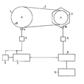
An einer Zeichnung, die eine Schaltungsanordnung zur Ausübung des Verfahrens als Blockschaltbild darstellt, wird die Erfindung erläutert.The invention is explained on a drawing which represents a circuit arrangement for carrying out the method as a block diagram.
Eine Keilriemenscheibe 1 ist mit der Kurbelwelle einer nicht dargestellten Brennkraftmaschine verbunden. Das Drehmoment der Keilriemenscheibe 1 wird über einen Keilriemen 2 an eine Keilriemenscheibe 3 übertragen, die am Wellenende eines ebenfalls nicht dargestellten elektrischen Generators befestigt ist. Die Keilriemenscheibe 1 bzw. die sie antreibende Kurbelwelle trägt eine beispielsweise den oberen Totpunkt kennzeichnende Marke, die beim Umlaufen von einem Totpunktsensor 4 detektiert wird. An den Totpunktsensor sind über einen Impulsformer 5 der Eingang eines Drehzahlmessers 6 und der Zähleingang eines ersten Zählers 7 angeschlossen. Über ein vom Ausgang des Drehzahlmessers 6 in einem festzulegenden Drehzahlbereich abhängiges Signal wird der Zähleingang des Zählers 7 gesteuert. Der Zähler 7 zählt also nur während eines bestimmten Drehzahlbereiches die vom Totpunktsensor 4 ausgehenden Impulse. Der Zähleingang eines zweiten Zählers 8 ist über einen zweiten Impulsformer 9 an die sogenannte W-Klemme 10 des Generators angeschlossen, der von der Keilriemenscheibe 3 angetrieben wird. An der W-Klemme können Impulse abgenommen werden, deren Rate proportional der Drehzahl des Generators und der Polpaarzahl seines Läufers ist. Ein Start/Stopp-Eingang des zweiten Zählers 8 ist mit einem Ausgang des Zählers 7 verbunden und empfängt ein Signal, während im Zähler 7 eine vorgegebene Anzahl von Impulsen des Totpunktsensors 4 einläuft. Der zweite Zähler 8 zählt von der W-Klemme ausgehende Impulse, während im Zähler 7 eine bestimmte Anzahl von Impulsen des Totpunktsensors 4 einläuft. Eine Recheneinheit 11 verarbeitet die im Zähler 8 erhaltene Zahl zum gesuchten Schlupf zwischen Brennkraftmaschine und Generator nach dem Ausdruck
Claims (10)
Applications Claiming Priority (2)
| Application Number | Priority Date | Filing Date | Title |
|---|---|---|---|
| DE19823204783 DE3204783C2 (en) | 1982-02-11 | 1982-02-11 | Circuit arrangement for determining the mechanical tension of a V-belt |
| DE3204783 | 1982-02-11 |
Publications (3)
| Publication Number | Publication Date |
|---|---|
| EP0086433A2 true EP0086433A2 (en) | 1983-08-24 |
| EP0086433A3 EP0086433A3 (en) | 1984-08-29 |
| EP0086433B1 EP0086433B1 (en) | 1987-05-20 |
Family
ID=6155399
Family Applications (1)
| Application Number | Title | Priority Date | Filing Date |
|---|---|---|---|
| EP19830101150 Expired EP0086433B1 (en) | 1982-02-11 | 1983-02-07 | Circuit for determining the tension in a v-belt |
Country Status (2)
| Country | Link |
|---|---|
| EP (1) | EP0086433B1 (en) |
| DE (1) | DE3204783C2 (en) |
Cited By (7)
| Publication number | Priority date | Publication date | Assignee | Title |
|---|---|---|---|---|
| FR2605110A1 (en) * | 1986-10-14 | 1988-04-15 | Equip Electr Moteurs | DEVICE FOR DETECTING THE SLIDING OF THE DRIVE BELT OF AN ENGINE DRIVEN ELECTRIC GENERATING MACHINE |
| EP0337100A2 (en) * | 1988-03-31 | 1989-10-18 | Heidelberger Druckmaschinen Aktiengesellschaft | Method and apparatus for measuring rotation speed |
| EP0767055A2 (en) * | 1995-10-04 | 1997-04-09 | MAN Roland Druckmaschinen AG | Monitoring device for the driving device of a printing machine |
| EP1098186A1 (en) * | 1999-11-04 | 2001-05-09 | Gerber Garment Technology, Inc. | Inertia-testing method and system |
| EP1111394A1 (en) * | 1999-12-08 | 2001-06-27 | Robert Bosch Gmbh | Device for determining slip and tension of a vehicle v-belt |
| FR2848631A1 (en) * | 2002-12-17 | 2004-06-18 | Peugeot Citroen Automobiles Sa | Connection mechanism state diagnostic system for swiveling machine e.g. alternator of vehicle, has comparison unit comparing correlation information from determination unit with threshold to evaluate state of connection mechanism |
| EP2058640A2 (en) * | 2007-11-07 | 2009-05-13 | Sensdata Limited | Apparatus and method for monitoring a system |
Families Citing this family (2)
| Publication number | Priority date | Publication date | Assignee | Title |
|---|---|---|---|---|
| DE4117530A1 (en) * | 1991-05-29 | 1992-12-03 | Claas Ohg | V-BELT DRIVE |
| DE10112568A1 (en) * | 2001-03-15 | 2002-10-02 | Bosch Gmbh Robert | Process for detecting slip in generator and start generator systems |
Citations (1)
| Publication number | Priority date | Publication date | Assignee | Title |
|---|---|---|---|---|
| US4263578A (en) * | 1978-06-08 | 1981-04-21 | Nissan Motor Company, Limited | Belt drive connection malfunction sensor |
Family Cites Families (1)
| Publication number | Priority date | Publication date | Assignee | Title |
|---|---|---|---|---|
| DE2201209A1 (en) * | 1972-01-12 | 1973-07-26 | Bosch Gmbh Robert | PROCEDURE AND DEVICE FOR DETERMINING THE TENSION OF BELTS, IN PARTICULAR V-BELTS ON INTERNAL ENGINEERING MACHINES |
-
1982
- 1982-02-11 DE DE19823204783 patent/DE3204783C2/en not_active Expired
-
1983
- 1983-02-07 EP EP19830101150 patent/EP0086433B1/en not_active Expired
Patent Citations (1)
| Publication number | Priority date | Publication date | Assignee | Title |
|---|---|---|---|---|
| US4263578A (en) * | 1978-06-08 | 1981-04-21 | Nissan Motor Company, Limited | Belt drive connection malfunction sensor |
Cited By (13)
| Publication number | Priority date | Publication date | Assignee | Title |
|---|---|---|---|---|
| FR2605110A1 (en) * | 1986-10-14 | 1988-04-15 | Equip Electr Moteurs | DEVICE FOR DETECTING THE SLIDING OF THE DRIVE BELT OF AN ENGINE DRIVEN ELECTRIC GENERATING MACHINE |
| EP0267087A1 (en) * | 1986-10-14 | 1988-05-11 | Valeo Equipements Electriques Moteur | Belt slip detection apparatus for an electrical generator driven by an engine |
| EP0337100A2 (en) * | 1988-03-31 | 1989-10-18 | Heidelberger Druckmaschinen Aktiengesellschaft | Method and apparatus for measuring rotation speed |
| EP0337100A3 (en) * | 1988-03-31 | 1992-07-08 | Heidelberger Druckmaschinen Aktiengesellschaft | Method and apparatus for measuring rotation speed |
| EP0767055A2 (en) * | 1995-10-04 | 1997-04-09 | MAN Roland Druckmaschinen AG | Monitoring device for the driving device of a printing machine |
| EP0767055A3 (en) * | 1995-10-04 | 1997-08-27 | Roland Man Druckmasch | Monitoring device for the driving device of a printing machine |
| EP1098186A1 (en) * | 1999-11-04 | 2001-05-09 | Gerber Garment Technology, Inc. | Inertia-testing method and system |
| US6370969B1 (en) | 1999-11-04 | 2002-04-16 | Gerber Technology, Inc. | Inertia-testing method and system |
| EP1111394A1 (en) * | 1999-12-08 | 2001-06-27 | Robert Bosch Gmbh | Device for determining slip and tension of a vehicle v-belt |
| FR2848631A1 (en) * | 2002-12-17 | 2004-06-18 | Peugeot Citroen Automobiles Sa | Connection mechanism state diagnostic system for swiveling machine e.g. alternator of vehicle, has comparison unit comparing correlation information from determination unit with threshold to evaluate state of connection mechanism |
| EP2058640A2 (en) * | 2007-11-07 | 2009-05-13 | Sensdata Limited | Apparatus and method for monitoring a system |
| GB2454471A (en) * | 2007-11-07 | 2009-05-13 | Sensdata Ltd | Apparatus For Monitoring The Efficiency Of A Pulley System |
| EP2058640A3 (en) * | 2007-11-07 | 2011-05-04 | Sensdata Limited | Apparatus and method for monitoring a system |
Also Published As
| Publication number | Publication date |
|---|---|
| DE3204783A1 (en) | 1983-08-18 |
| DE3204783C2 (en) | 1985-01-31 |
| EP0086433B1 (en) | 1987-05-20 |
| EP0086433A3 (en) | 1984-08-29 |
Similar Documents
| Publication | Publication Date | Title |
|---|---|---|
| DE4431720C1 (en) | Method and device for determining the rotational speed of internal combustion engines | |
| DE3408492C2 (en) | ||
| EP0086433B1 (en) | Circuit for determining the tension in a v-belt | |
| DE3126962A1 (en) | DEVICE FOR AUTOMATICALLY INDICATING AN INSUFFICIENT OIL LEVEL IN AN AUTOMATIC MANUAL GEARBOX FOR MOTOR VEHICLES | |
| EP0704689B1 (en) | Procedure for determining the moment of inertia | |
| DE2633880C2 (en) | ||
| EP0441769B1 (en) | Control device for an automobile | |
| DE94332T1 (en) | GRAPHIC RECORDING OF THE PARAMETERS OF AN ENGINE CYLINDER. | |
| DE3026232C2 (en) | Method and device for displaying the size of an imbalance when balancing rotors | |
| DE19959096A1 (en) | Arrangement for determining the slip or the V-belt tension in an internal combustion engine | |
| DE102021204884A1 (en) | Device for measuring an indicative parameter of the rotational speed of a component | |
| EP0560793B1 (en) | Method of detecting irregular combustion in an engine cylinder | |
| DE2910306A1 (en) | PROCEDURE FOR TESTING ENGINES AND TESTING DEVICE FOR CARRYING OUT THE PROCEDURE | |
| DE3118195A1 (en) | "METHOD FOR DETERMINING THE FUEL CONSUMPTION OF VEHICLES" | |
| DE2755424A1 (en) | Slip measurement device with direct indication - operates using pick=ups generating pulses induced by belt and pulley markers | |
| EP0895089B1 (en) | Device for determining the rotational speed of a combustion engine | |
| DE19825023C2 (en) | Method and arrangement for determining the engine speed of a motor vehicle | |
| DE3333671A1 (en) | Method and device for determining the r.p.m./torque characteristic of an engine of a motor vehicle | |
| DE2658733C2 (en) | Display device for several measured variables in motor vehicles | |
| DE19753064C2 (en) | Method and device for testing rings with a large number of magnetic poles | |
| DE19933105A1 (en) | Method for checking and/or monitoring gears for defects includes frequency analysis | |
| DE2201209A1 (en) | PROCEDURE AND DEVICE FOR DETERMINING THE TENSION OF BELTS, IN PARTICULAR V-BELTS ON INTERNAL ENGINEERING MACHINES | |
| WO1999060365A1 (en) | Wheel suspension tester | |
| DE2253418C3 (en) | Device and method for determining the ignition angle of internal combustion engines | |
| DE3644189C2 (en) |
Legal Events
| Date | Code | Title | Description |
|---|---|---|---|
| PUAI | Public reference made under article 153(3) epc to a published international application that has entered the european phase |
Free format text: ORIGINAL CODE: 0009012 |
|
| PUAI | Public reference made under article 153(3) epc to a published international application that has entered the european phase |
Free format text: ORIGINAL CODE: 0009012 |
|
| AK | Designated contracting states |
Designated state(s): FR GB IT |
|
| PUAL | Search report despatched |
Free format text: ORIGINAL CODE: 0009013 |
|
| AK | Designated contracting states |
Designated state(s): FR GB IT |
|
| 17P | Request for examination filed |
Effective date: 19841221 |
|
| GRAA | (expected) grant |
Free format text: ORIGINAL CODE: 0009210 |
|
| AK | Designated contracting states |
Kind code of ref document: B1 Designated state(s): FR GB IT |
|
| ET | Fr: translation filed | ||
| ITF | It: translation for a ep patent filed |
Owner name: STUDIO JAUMANN |
|
| PLBE | No opposition filed within time limit |
Free format text: ORIGINAL CODE: 0009261 |
|
| STAA | Information on the status of an ep patent application or granted ep patent |
Free format text: STATUS: NO OPPOSITION FILED WITHIN TIME LIMIT |
|
| 26N | No opposition filed | ||
| PGFP | Annual fee paid to national office [announced via postgrant information from national office to epo] |
Ref country code: GB Payment date: 19910118 Year of fee payment: 9 |
|
| PGFP | Annual fee paid to national office [announced via postgrant information from national office to epo] |
Ref country code: FR Payment date: 19910219 Year of fee payment: 9 |
|
| ITTA | It: last paid annual fee | ||
| PG25 | Lapsed in a contracting state [announced via postgrant information from national office to epo] |
Ref country code: GB Effective date: 19920207 |
|
| GBPC | Gb: european patent ceased through non-payment of renewal fee | ||
| PG25 | Lapsed in a contracting state [announced via postgrant information from national office to epo] |
Ref country code: FR Effective date: 19921030 |
|
| REG | Reference to a national code |
Ref country code: FR Ref legal event code: ST |