EP0086418A2 - Verfahren und Gerät zum Einbringen von länglichen zylindrischen Elementen in vorgebohrte Löcher - Google Patents
Verfahren und Gerät zum Einbringen von länglichen zylindrischen Elementen in vorgebohrte Löcher Download PDFInfo
- Publication number
- EP0086418A2 EP0086418A2 EP83101100A EP83101100A EP0086418A2 EP 0086418 A2 EP0086418 A2 EP 0086418A2 EP 83101100 A EP83101100 A EP 83101100A EP 83101100 A EP83101100 A EP 83101100A EP 0086418 A2 EP0086418 A2 EP 0086418A2
- Authority
- EP
- European Patent Office
- Prior art keywords
- hole
- sleeve
- tool
- striker
- procedure
- Prior art date
- Legal status (The legal status is an assumption and is not a legal conclusion. Google has not performed a legal analysis and makes no representation as to the accuracy of the status listed.)
- Withdrawn
Links
Images
Classifications
-
- B—PERFORMING OPERATIONS; TRANSPORTING
- B25—HAND TOOLS; PORTABLE POWER-DRIVEN TOOLS; MANIPULATORS
- B25B—TOOLS OR BENCH DEVICES NOT OTHERWISE PROVIDED FOR, FOR FASTENING, CONNECTING, DISENGAGING OR HOLDING
- B25B27/00—Hand tools, specially adapted for fitting together or separating parts or objects whether or not involving some deformation, not otherwise provided for
- B25B27/02—Hand tools, specially adapted for fitting together or separating parts or objects whether or not involving some deformation, not otherwise provided for for connecting objects by press fit or detaching same
- B25B27/04—Hand tools, specially adapted for fitting together or separating parts or objects whether or not involving some deformation, not otherwise provided for for connecting objects by press fit or detaching same inserting or withdrawing keys
-
- B—PERFORMING OPERATIONS; TRANSPORTING
- B25—HAND TOOLS; PORTABLE POWER-DRIVEN TOOLS; MANIPULATORS
- B25C—HAND-HELD NAILING OR STAPLING TOOLS; MANUALLY OPERATED PORTABLE STAPLING TOOLS
- B25C3/00—Portable devices for holding and guiding nails; Nail dispensers
- B25C3/006—Portable devices for holding and guiding nails; Nail dispensers only for holding and guiding
Definitions
- the present invention refers to a procedure for mounting elongated, principally cylindrical elements such as expander pins in predrilled holes, for example.
- Expander pins are resilient locking pins used for the demountable assembly of various machine elements or mechanical components, e.g. for mounting wheels and the like on shafts.
- the expanding capability is usually achieved by designing the expander pin as a slotted, springy sleeve of alloy steel which is made resilient by heat treatment.
- Expander pins are mounted in holes having a diameter less than that of the pin, with the result that the pin is compressed when driven into the hole. Since the pin endeavours to spring back to its normal expanding state it exerts sufficient pressure against the inner surface of the hole to prevent axial movement.
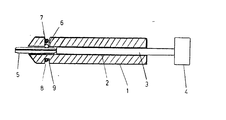
- FIG. 1 shows a longitudinal cross-section through a tool according to the invention.
- the tool consists of a sleeve 1 which is provided with an axial through hole 2.
- a striker 3 is so arranged in the hole 2 that it can move in an axial direction.
- the end of striker 3 outside the sleeve 1 is designed as an impact head 4.
- the cylindrical element which in the version shown consists of an expander pin 5 is arranged to be accommodated in the hole 2 at the opposite end of the sleeve 1 to the aforementioned impact head 4.
- a chiefly radial hole 6 is provided in the sleeve 1 close to the end accommodating expander pin 5.
- a loosely fitted locking pin 7 which rests against the expander pin.
- This locking pin is retained and pressed resiliently against the expander pin 5 by a rubber ring 8.
- the rubber ring 8 is fitted in an annular groove 9 in the surface of sleeve 1 adjacent to the radial hole 6. The resilience of rubber ring 8 is adapted so that expander pin 5 is retained by the friction, even when the tool is pointed downward, but not so that mounting of the pin is noticeably obstructed.
- a corresponding locking device can be utilized to retain the striker 3 in sleeve 1.
- a return spring (not shown) can be arranged between the striker and the sleeve to return the striker to the position of rest after each blow. Further, the aforementioned striker can be provided with a means of restricting its outward movement.
- the spring force applied to expander pin 5 from the side can naturally be arranged in many ways and the version described above is only an example.
- the tool can also be designed for easy connection to the pneumatic impact tool.
- the pin 5 When using the tool described above for mounting an expander pin 5 in a predrilled hole, the pin 5 is first fitted in the hole 2 in the sleeve 1. Locking pin 7 is pressed against expander pin 5 by means of rubber ring 8. The sleeve 1 is then applied to the predrilled hole and expander pin 5 is located in its mouth. Impact head 4 is subjected to repeated blows with the effect that the striker 3 strikes expander pin 5 and drives it into the hole.
Landscapes
- Engineering & Computer Science (AREA)
- Mechanical Engineering (AREA)
- Refuge Islands, Traffic Blockers, Or Guard Fence (AREA)
- Dowels (AREA)
- Emergency Lowering Means (AREA)
- Clamps And Clips (AREA)
- Mechanical Pencils And Projecting And Retracting Systems Therefor, And Multi-System Writing Instruments (AREA)
Applications Claiming Priority (2)
| Application Number | Priority Date | Filing Date | Title |
|---|---|---|---|
| SE8200827 | 1982-02-11 | ||
| SE8200827A SE8200827L (sv) | 1982-02-11 | 1982-02-11 | Forfarande och verktyg for montering av langstreckta, cylindriska element i forborrade hal |
Publications (2)
| Publication Number | Publication Date |
|---|---|
| EP0086418A2 true EP0086418A2 (de) | 1983-08-24 |
| EP0086418A3 EP0086418A3 (de) | 1984-09-12 |
Family
ID=20345982
Family Applications (1)
| Application Number | Title | Priority Date | Filing Date |
|---|---|---|---|
| EP83101100A Withdrawn EP0086418A3 (de) | 1982-02-11 | 1983-02-07 | Verfahren und Gerät zum Einbringen von länglichen zylindrischen Elementen in vorgebohrte Löcher |
Country Status (2)
| Country | Link |
|---|---|
| EP (1) | EP0086418A3 (de) |
| SE (1) | SE8200827L (de) |
Cited By (4)
| Publication number | Priority date | Publication date | Assignee | Title |
|---|---|---|---|---|
| EP1506844A1 (de) * | 2003-08-12 | 2005-02-16 | The Goodyear Tire & Rubber Company | Werkzeug und Verfahren zum Einführen von Reifensensoren |
| CN103978460A (zh) * | 2014-05-23 | 2014-08-13 | 安徽江淮汽车股份有限公司 | 卷收器拆装工具 |
| CN106985121A (zh) * | 2017-04-30 | 2017-07-28 | 桂林电子科技大学 | 一种可多次利用的压溃式钉子辅助装置及其工作方法 |
| CN110270964A (zh) * | 2019-06-24 | 2019-09-24 | 中国五冶集团有限公司 | 一种用于辅助敲击钉子的钉筒 |
Family Cites Families (6)
| Publication number | Priority date | Publication date | Assignee | Title |
|---|---|---|---|---|
| US2839754A (en) * | 1957-03-22 | 1958-06-24 | Elmer F Pfaff | Fastener driving tool |
| US2973520A (en) * | 1959-06-16 | 1961-03-07 | Star Prec Devices Inc | Small diameter stud adapter |
| US3036482A (en) * | 1960-09-02 | 1962-05-29 | Kenworthy Kenneth | Axial-impact type hand tool |
| US3788537A (en) * | 1972-07-31 | 1974-01-29 | Mechanical Applic Inc | Hand-loaded pin chuck |
| US3979978A (en) * | 1974-05-15 | 1976-09-14 | Smolik Robert A | Nail setting tool |
| FR2291001A2 (fr) * | 1974-11-18 | 1976-06-11 | Chatard Henri | Dispositif pour planter des clous adaptable sur une chignole electrique |
-
1982
- 1982-02-11 SE SE8200827A patent/SE8200827L/ unknown
-
1983
- 1983-02-07 EP EP83101100A patent/EP0086418A3/de not_active Withdrawn
Cited By (6)
| Publication number | Priority date | Publication date | Assignee | Title |
|---|---|---|---|---|
| EP1506844A1 (de) * | 2003-08-12 | 2005-02-16 | The Goodyear Tire & Rubber Company | Werkzeug und Verfahren zum Einführen von Reifensensoren |
| US7021164B2 (en) | 2003-08-12 | 2006-04-04 | The Goodyear Tire & Rubber Company | Tire sensor insertion tool and method |
| CN103978460A (zh) * | 2014-05-23 | 2014-08-13 | 安徽江淮汽车股份有限公司 | 卷收器拆装工具 |
| CN106985121A (zh) * | 2017-04-30 | 2017-07-28 | 桂林电子科技大学 | 一种可多次利用的压溃式钉子辅助装置及其工作方法 |
| CN106985121B (zh) * | 2017-04-30 | 2023-03-10 | 桂林电子科技大学 | 一种可多次利用的压溃式钉子辅助装置及其工作方法 |
| CN110270964A (zh) * | 2019-06-24 | 2019-09-24 | 中国五冶集团有限公司 | 一种用于辅助敲击钉子的钉筒 |
Also Published As
| Publication number | Publication date |
|---|---|
| SE8200827L (sv) | 1983-08-12 |
| EP0086418A3 (de) | 1984-09-12 |
Similar Documents
| Publication | Publication Date | Title |
|---|---|---|
| US2851295A (en) | Socket adaptor | |
| CA1256717A (en) | Tool holder for drilling and chiselling tools | |
| US4202557A (en) | Drilling device | |
| EP0395335A1 (de) | Meissel zum Bohren eines hinterschnittenen Loches | |
| US2576786A (en) | Centralizing drill | |
| US3152391A (en) | Tool for wheel weights | |
| US3633640A (en) | Tool having retractable and removable centering sleeve | |
| US3209445A (en) | Combination tool for driving out an old bushing and driving in a new one | |
| US8028762B2 (en) | Shock absorber for a reciprocating tool assembly | |
| CN113459024B (zh) | 用于动力工具的套筒保持装置 | |
| EP0086418A2 (de) | Verfahren und Gerät zum Einbringen von länglichen zylindrischen Elementen in vorgebohrte Löcher | |
| EP4058245A1 (de) | Schlagwerksanordnung | |
| US5100256A (en) | Retaining pin module | |
| US4073046A (en) | Shock absorber installation tool | |
| US2701359A (en) | Hand tool | |
| SU1253767A1 (ru) | Устройство дл креплени рабочего инструмента в машине ударного действи | |
| GB2136725A (en) | Hammer, in particular drill hammer | |
| US4174848A (en) | Latching mechanism for reciprocating impact tools | |
| US1613399A (en) | Chisel retainer for riveting hammers | |
| EP0684095A1 (de) | Stanzwerkzeug | |
| US2451234A (en) | Compression member | |
| US4550784A (en) | Tool mounting means for a hydraulically powered impact hammer | |
| GB1566637A (en) | Rotary impact tool | |
| GB1566340A (en) | Rotary percussion drilling devices | |
| US5533660A (en) | Expansion dowel and expansion dowel setting tool |
Legal Events
| Date | Code | Title | Description |
|---|---|---|---|
| PUAI | Public reference made under article 153(3) epc to a published international application that has entered the european phase |
Free format text: ORIGINAL CODE: 0009012 |
|
| PUAI | Public reference made under article 153(3) epc to a published international application that has entered the european phase |
Free format text: ORIGINAL CODE: 0009012 |
|
| AK | Designated contracting states |
Designated state(s): CH DE FR GB IT LI |
|
| 17P | Request for examination filed |
Effective date: 19840221 |
|
| PUAL | Search report despatched |
Free format text: ORIGINAL CODE: 0009013 |
|
| AK | Designated contracting states |
Designated state(s): CH DE FR GB IT LI |
|
| STAA | Information on the status of an ep patent application or granted ep patent |
Free format text: STATUS: THE APPLICATION HAS BEEN WITHDRAWN |
|
| 18W | Application withdrawn |
Withdrawal date: 19850402 |
|
| RIN1 | Information on inventor provided before grant (corrected) |
Inventor name: PUOLAKAINEN, NIKOLAI |