EP0086414B1 - Auxiliary device for vehicular safety-belt with automatic retractor - Google Patents
Auxiliary device for vehicular safety-belt with automatic retractor Download PDFInfo
- Publication number
- EP0086414B1 EP0086414B1 EP83101062A EP83101062A EP0086414B1 EP 0086414 B1 EP0086414 B1 EP 0086414B1 EP 83101062 A EP83101062 A EP 83101062A EP 83101062 A EP83101062 A EP 83101062A EP 0086414 B1 EP0086414 B1 EP 0086414B1
- Authority
- EP
- European Patent Office
- Prior art keywords
- base plate
- belt
- auxiliary device
- belts
- additional
- Prior art date
- Legal status (The legal status is an assumption and is not a legal conclusion. Google has not performed a legal analysis and makes no representation as to the accuracy of the status listed.)
- Expired
Links
Images
Classifications
-
- B—PERFORMING OPERATIONS; TRANSPORTING
- B60—VEHICLES IN GENERAL
- B60R—VEHICLES, VEHICLE FITTINGS, OR VEHICLE PARTS, NOT OTHERWISE PROVIDED FOR
- B60R22/00—Safety belts or body harnesses in vehicles
- B60R22/18—Anchoring devices
- B60R22/19—Anchoring devices with means for reducing belt tension during use under normal conditions
Definitions
- the present invention relates to an additional device for motor vehicle seat belts with an automatic rewinding device, with a base plate and a movable clamping part arranged thereon, and at least one belt deflector as a fastening point for the base plate.
- Such short belt channels are still used by certain automobile manufacturers. Mandiese also finds relatively long free distances of 10 and more cm with belts that have been installed subsequently.
- automobile types have also become known in which the free distance between the upper outlet from the belt channel and the deflection point is only a few cm.
- the deflection device is arranged directly concealed in bodywork shafts, the belts being guided to the outside only through a relatively narrow gap.
- the known additional devices are not suitable for attachment to long guide channels or closed guide channels, as are provided in particular in more expensive automobiles.
- the present invention aims to create a universally usable additional device which can be easily adapted to all belt systems that have become known.
- Such an additional device is characterized in that a hook-shaped additional organ, for. B. an additional clamp is provided, which makes it possible to connect the base plate with the belt deflector.
- the system for motor vehicle seat belts with an automatic rewind device comprises a spring-loaded roller 1 in a housing 2, which is fastened to a body 3 of a vehicle.
- the spring-loaded roller 1 serves to accommodate a restraint belt 40, the behavior of which will be explained in detail later.
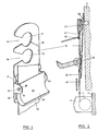
- the additional device which allows the restraint belts 40 to be passed over the chest of the driver to be belted in a loose state, has a base plate 10 with two openings 11 and 12 lying one above the other.
- the openings 11 and 12 are open via an extension 13 and 14 on one side. These openings 11 and 12 serve to hold the base plate 10 to a body part.
- the web lying between the two openings 11 and 12 is so flexible that the corresponding extension 13 or 14 can be stretched for pushing on the plate 10 without this leading to the plate 10 breaking.
- the base plate 10 is also provided with a parting line 16, which allows the upper part to be broken away when the lower opening 12 is used, so that it does not interfere with the attachment of the remaining additional device. According to FIGS.
- FIG. 2 shows part of a car interior, a relatively long belt channel 43 being provided, but which does not extend as far as a fastening screw 46 provided in the body.
- a fastening screw 46 provided in the body.
- the screw 46 can be covered by means of a plastic cover 47 for a better appearance.
- the additional device can be fastened to the upper opening 11. If the belt channel is guided all the way to the fastening screw 46, the additional device must be attached to the belt deflection 42 with the additional clamp, as described subsequently.
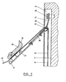
- a vehicle-side belt channel 44 is provided in the sense of FIG. 7.
- the channel 44 has a slot 45 at the usual height for leading the belts 40 out.
- the fastening screw 46 is fastened here in the interior of the belt channel 44.
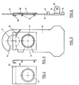
- an additional clip 50 which has a flanged, preferably segmented edge 51 and an upper hook 53 in the form of a hook.
- the edge 51 and the hanger 53 form two clamping elements.
- the attachment of such a clip 50 is indicated in FIGS. 3 and 6.
- This clip 50 can be made of an elastic material, e.g. B. sheet steel, plastic or the like. It allows the front part of the base plate 10 with the clamp 50 mounted thereon and this structure to be suspended by means of the upper hanger 53 around the deflector 42. The restraint belts 40 are then passed over the upper hanger 53 and the clamps 50 and then get between the clamping part 30 and the base plate 10.
- the clamping part 30 in the bearing blocks 24 is pivoted by 180 ° with respect to the position according to FIG. 2, such that a train on the restraining belts 40 in the direction of the arrow pivots the clamping part 30 and the clamping surface 35 except Engagement with the straps 40 brings.
- the restraining belts 40 are in turn freely movable. It is in turn under the tension of the spring-loaded roller 1.
- This version of the additional device with the spring steel sheet can be attached to all previously known motor vehicle seat belt systems.
- the base plate In the case of very short belt channels, the base plate is hung in the upper opening 11, in the case of longer ones in the opening 12, the upper part of the base plate 10 being broken off at the parting line 16, and in the case of belts which are completely installed on the vehicle, with belt channels 44, as shown in FIG. 7 shows, the additional device is arranged by hanging in the manner shown in Fig. In any case, a pull on the restraining belts 40 against the spring force of the roll 1 is sufficient to free it from the retention by means of the clamping part 30 and in turn place it under the pull of the automatic rewinding device.
- the analogous arrangement takes place when the deflection carrier 41 with deflector 42 above, for. B. on the roof, or when the slot 45 is in the roof.
Landscapes
- Engineering & Computer Science (AREA)
- Mechanical Engineering (AREA)
- Automotive Seat Belt Assembly (AREA)
- Pens And Brushes (AREA)
- Finger-Pressure Massage (AREA)
- Massaging Devices (AREA)
Abstract
Description
Die vorliegende Erfindung betrifft eine Zusatzvorrichtung für Kraftfahrzeugsicherheitsgurte mit automatischer Rückspulvorrichtung, mit einer Grundplatte und einem an dieser angeordneten beweglichen Klemmteil sowie mindestens einem Gurtenumlenker als Befestigungsstelle für die Grundplatte.The present invention relates to an additional device for motor vehicle seat belts with an automatic rewinding device, with a base plate and a movable clamping part arranged thereon, and at least one belt deflector as a fastening point for the base plate.
Bei den heute bekannten, zumeist benützten Sitzgurten ist deren eines Ende durch eine federbelastete Rolle ständig so aufgespult und gespannt gehaltert, dass langsame Ausziehbewegungen der Sitzgurte und mithin des angegurteten Insassen entgegen der Federkraft ermöglicht werden. Bei einer plötzlichen Bewegung, d.h. grossen Beschleunigungen, wird die Sitzgurte infolge der Massenträgheit, wie sie beispielsweise bei plötzlichen Verzögerungen des Kraftfahrzeuges bei Berührung mit einem Hindernis auftreten können, durch die Feder blockiert und die Gurte an ihren beiden Enden festgehalten, so dass sie die von ihr verlangte Rückhaltefunktion ausüben kann.In the seat belts known today, mostly used, one end of which is constantly wound and tensioned by a spring-loaded roller so that slow pull-out movements of the seat belts and thus the belted occupant are made possible against the spring force. With a sudden movement, i.e. large accelerations, the seat belts are blocked by the spring due to the inertia, as can occur, for example, in the event of sudden decelerations of the motor vehicle in contact with an obstacle, and the belts are held at both ends so that they can perform the restraint function required by them.
Normalerweise wird diese Gurte heutzutage schon von den Automobilherstellern angebracht, wobei deren Anbringen auf unterschiedliche Weise erfolgt. Die Benutzung dieser Gurte, welche ständig unter Federspannung steht, wird oft als lästig empfunden, insbesondere da sie über die oberen Brustpartien gelegt wird und daher bei vielen Fahrern ein unangenehmes Beklemmungsgefühl erregt.These belts are usually already fitted by automobile manufacturers today, but they are attached in different ways. The use of these belts, which are constantly under spring tension, is often perceived as annoying, especially since they are placed over the upper chest areas and therefore create an uncomfortable feeling of oppression among many drivers.
Aus diesem Grunde wurde eine Zusatzvorrichtung für derartige Kraftfahrzeugssicherheitsgurten entwickelt, welche ermöglicht, die durch die Feder gegebene Vorspannung am Gurt zu lokkern, so dass der Benützer von keinem Gurtendruck eingeengt wird. Diese Zusatzvorrichtung ist derart konzipiert, das bei einem plötzlichen Auftreten einer Zugkraft entgegen dem Zug der eingebauten Feder die Zusatzvorrichtung automatisch geöffnet wird. Dadurch wird die Gurte unter Federspannung gesetzt, so dass auch die Blockiereinrichtung der Feder im dargelegten Sinne funktioniert. Diese Vorrichtung, die gemäss des Gattungsbegriffes des Anspruchs 1 angedeutet ist, ist vorher aus dem Dokument GB-A-2005130 bekannt. Diese bekannte Zusatzvorrichtung ist für diejenigen Automobile, bei welchen die Gurten vor ihrem Umlenken und dem Begurten des Fahrers über eine längere Strecke frei im Wageninnern verlaufen, vorgesehen. Solche kurzen Gurtenkanäle werden von gewissen Automobilherstellern weiterhin benutzt. Auch findet mandiese relativ langen freien Strecken von 10 und mehr cm bei Gurten, welche nachträglich eingebaut wurden. Es sind aber auch Automobiltypen bekannt geworden, bei denen die freie Strecke zwischen dem oberen Austritt aus dem Gurtenkanal und der Umlenkstelle nur einige cm beträgt. Auch gibt es Typen, bei welchen die Umlenkeinrichtung direkt verborgen in Karosserieschächten angeordnet ist, wobei die Gurte nur durch einen relativ schmalen Spalt nach aussen geleitet wird. Die bekannten Zusatzvorrichtungen eignen sich für das Anbringen bei langen Führungskanälen oder geschlossenen Führungskanälen, wie sie insbesondere bei teureren Automobilen vorgesehen sind, nicht.For this reason, an additional device for such motor vehicle seat belts has been developed, which makes it possible to loosen the prestress on the belt given by the spring, so that the user is not restricted by any belt pressure. This additional device is designed in such a way that the additional device is opened automatically in the event of a sudden occurrence of a tensile force against the tension of the built-in spring. As a result, the belts are placed under spring tension, so that the locking device of the spring also functions in the manner described. This device, which is indicated according to the preamble of claim 1, is previously known from document GB-A-2005130. This known additional device is intended for those automobiles in which the belts run freely over a longer distance inside the vehicle before they are deflected and the driver is belayed. Such short belt channels are still used by certain automobile manufacturers. Mandiese also finds relatively long free distances of 10 and more cm with belts that have been installed subsequently. However, automobile types have also become known in which the free distance between the upper outlet from the belt channel and the deflection point is only a few cm. There are also types in which the deflection device is arranged directly concealed in bodywork shafts, the belts being guided to the outside only through a relatively narrow gap. The known additional devices are not suitable for attachment to long guide channels or closed guide channels, as are provided in particular in more expensive automobiles.
Die vorliegende Erfindung bezweckt die Schaffung einer universell verwendbaren Zusatzvorrichtung, welche allen bisher bekannt gewordenen Gurtenanlagen mühelos angepasst werden kann.The present invention aims to create a universally usable additional device which can be easily adapted to all belt systems that have become known.
Eine derartige Zusatzvorrichtung zeichnet sich dadurch aus, dass ein hakenförmiges Zusatz-Organ, z. B. eine Zusatzklammer vorgesehen ist, welches es ermöglicht, die Grundplatte mit dem Gurtenumlenker zu verbinden.Such an additional device is characterized in that a hook-shaped additional organ, for. B. an additional clamp is provided, which makes it possible to connect the base plate with the belt deflector.
Der Erfindungsgegenstand wird anschliessend beispielsweise anhand einer Figur erläutert.The subject matter of the invention is subsequently explained, for example, using a figure.
Es zeigen:
- Fig. 1 eine perspektivische Darstellung einer Zusatzvorrichtung mit einem Teilstück einer eingezogenen Gurte, in gelöstem Zustand,
- Fig. 2 eine Seitenansicht einer Gurtenanlage, teilweise schematisch und teilweise im Schnitt dargestellt, mit relativ langem, am Fahrzeug befestigten Gurtenkanal,
- Fig. 3 eine Aufsicht auf die Zusatzvorrichtung gemäss Fig. 1, mit angebauter Zusatz-Klammer
- Fig. 4 eine Aufsicht auf eine Zusatz-Klammer
- Fig. 5 eine Seitenansicht der Zusatz-Klammer
- Fig. 6 eine mit der Grundplatte der Zusatzvorrichtung verbundene Zusatz-Klammer
- Fig. 7 eine schematische Ansicht einer Gurtenanlage, teilweise im Schnitt, in einem Automobil mit in einem Karosserie-Pfosten angeordneten Gurtenkanal.
- 1 is a perspective view of an additional device with a portion of a retracted belt, in the released state,
- 2 is a side view of a belt system, partly schematically and partly in section, with a relatively long belt channel attached to the vehicle,
- Fig. 3 is a plan view of the additional device according to FIG. 1, with the additional bracket attached
- Fig. 4 is a plan view of an additional bracket
- Fig. 5 is a side view of the additional bracket
- Fig. 6 is an additional bracket connected to the base plate of the additional device
- Fig. 7 is a schematic view of a belt system, partially in section, in an automobile with a belt channel arranged in a body post.
Die Anlage für Kraftfahrzeugsicherheitsgurte mit automatischer Rückspulvorrichtung umfasst eine federbelastete Rolle 1 in einem Gehäuse 2, welches an einer Karosserie 3 eines Fahrzeuges befestigt ist. Die federbelastete Rolle 1 dient der Aufnahme einer Rückhaltegurte40, deren Verhalten an späterer Stelle eingehend erläutert wird.The system for motor vehicle seat belts with an automatic rewind device comprises a spring-loaded roller 1 in a
Die Zusatzvorrichtung, welche erlaubt, die Rückhaltegurte 40 in losem Zustand vorn über die Brust des anzugurtenden Fahrers zu führen, weist eine Grundplatte 10 mit zwei übereinanderliegenden Öffnungen 11 und 12 auf. Die Öffnungen 11 und 12 sind über eine Erweiterung 13 bzw. 14 an einer Seite offen. Diese Öffnungen 11 und 12 dienen zum Festhalten der Grundplatte 10 an einem Karosserieteil. Der zwischen den beiden Öffnungen 11 und 12 liegende Steg ist derart flexibel, dass zum Aufschieben der Platte 10 die entsprechende Erweiterung 13 bzw. 14 gedehnt werden kann, ohne dass dies zum Bruch der Platte 10 führt. Die Grundplatte 10 ist ferner mit einer Trennfuge 16 versehen, welche erlaubt, bei Verwendung der unteren Öffnung 12 den oberen Teil wegzubrechen, damit er beim Anbringen der restlichen Zusatzvorrichtung nicht stört. Gemäss den Figuren 1 und 2 befinden sich im unteren Teil der Grundplatte 10 zwei Erhebungen 21 und 22, zwischen denen seitlich je ein Lagerbock 24 mit Öffnungen 26 angeordnet ist. Diese dienen der Aufnahme zweier Zapfen 32 eines Klemmteiles 30. Dessen längerer Hebelarm ist als Griff 34 ausgebildet, während der kürzere eine Klemmfläche 35 aufweist. Beim Nachaussenschwenken des Klemmteiles 30 in der Fig. 2 dargestellten Weise presst die Klemmfläche 35 die Rückhaltegurte 40 gegen die Grundplatte 10 und hält damit die Gurte 40 entgegen der Kraft der die Gurte einziehenden federbelasteten Rolle 1 fest.The additional device, which allows the
In Fig. 2 ist ein Teil eines Wageninneren dargestellt, wobei ein relativ langer Gurtenkanal 43 vorgesehen ist, der aber nicht bis zu einer vorgesehenen Befestigungsschraube 46 in der Karosserie reicht. Für diesen Fall ist vorgesehen, den oberen Teil der Grundplatte 10 längs der Trennfuge 16 wegzubrechen und über die Erweiterung 14 die Grundplatte 10 auf die Befestigungsschraube 46 zu schieben, so dass die Öffnung 12 diese Schraube 46 grösstenteils umfasst. Die Schraube 46 kann, wie Fig. 2 zeigt, mittels eines Kunststoffdeckels 47 zwecks besseren Aussehens abgedeckt werden.FIG. 2 shows part of a car interior, a relatively
Wenn der Gurtenkanal 43 zwischen seinem oberen Ende und der Befestigungsschraube 46 mehr Platz lässt, dann kann, wie bekannt, die Zusatzvorrichtung an der oberen Öffnung 11 befestigt werden. Wenn der Gurtenkanal bis ganz an die Befestigungsschraube 46 geführt ist, muss, wie anschliessend beschrieben, mit der Zusatz- klammer die Zusatzvorrichtung an der Gurtenumlenkung 42 eingehängt werden.As is known, if the
Es sind aber heute Automobile auf dem Markt, insbesondere teurere Marken, bei welchen ein fahrzeugseitiger Gurtenkanal 44 im Sinne der Fig. 7 vorgesehen ist. Der Kanal 44 weist auf üblicher Höhe einen Schlitz 45 zum Herausführen der Gurte 40 auf. Die Befestigungsschraube 46 ist hier, wie ersichtlich, im Inneren des Gurtenkanals 44 befestigt.However, there are automobiles on the market today, in particular more expensive brands, in which a vehicle-
Um für den Fall der Ausführung gemäss Fig. 7 die Zusatzvorrichtung ebenfalls anbringen zu können, wird diese mit einer Zusatzklammer 50, die einen gebördelten, vorzugsweise segmentierten Rand 51 und einen oberen Einhänger 53 in Hakenform aufweist, ergänzt. Der Rand 51 und der Einhänger 53 bilden zwei Klemmelemente. Das Anbringen einer derartigen Klammer 50 ist in den Fig. 3 und 6 angedeutet. Diese Klammer 50 kann aus einem elastischen Material, z. B. Stahlblech, Kunststoff o. dgl. hergestellt sein. Sie ermöglicht das Vorschieben des Vorderteils der Grundplatte 10 mit der darauf montierten Klammer 50 und Einhängen dieses Gebildes mittels des oberen Einhängers 53 um den Umlenker 42. Die Rückhaltegurte 40 wird dann über den oberen Einhänger 53 und die Klammern 50 geführt und gelangt anschliessend zwischen den Klemmteil 30 und die Grundplatte 10. Bei dieser Anwendung ist der Klemmteil 30 in den Lagerböcken 24 gegenüber der Lage gemäss Fig. 2 um 180° geschwenkt, derart, dass wiederum ein Zug auf die Rückhaltegurte 40 in Pfeilrichtung den Klemmteil 30 verschwenkt und die Klemmfläche 35 ausser Eingriff mit der Gurte 40 bringt. Damit wird die Rückhaltegurte 40 wiederum frei beweglich. Sie steht wiederum unter dem Zug der federbelasteten Rolle 1.In order to also be able to attach the additional device in the case of the embodiment according to FIG. 7, this is supplemented with an
Diese Ausführung der Zusatzvorrichtung mit dem Federstahlblatt ist an allen bisher bekannten Kraftfahrzeugsicherheitsgurtenanlagen anbringbar. Bei sehr kurzen Gurtenkanälen wird die Grundplatte in die obere Öffnung 11 eingehängt, bei längeren in die Öffnung 12, wobei der obere Teil der Grundplatte 10 an der Trennfuge 16 abgebrochen wird, und bei fahrzeugseitig ganz eingebauten Gurten mit Gurtenkanälen 44, wie sie Fig. 7 zeigt, wird die Zusatzvorrichtung durch Einhängen in der in Fig. dargestellten Weise angeordnet. In jedem Fall genügt ein Zug auf die Rückhaltegurte 40 entgegen der Federkraft der Rolle 1, um diese aus der Festhaltung mittels des Klemmteiles 30 zu befreien und sie wiederum unter den Zug der automatischen Rückspulvorrichtung zu stellen.This version of the additional device with the spring steel sheet can be attached to all previously known motor vehicle seat belt systems. In the case of very short belt channels, the base plate is hung in the
Die analoge Anordnung erfolgt, wenn der Umlenkträger 41 mit Umlenker 42 oben, z. B. am Dach, befestigt ist oder wenn sich der Schlitz 45 im Dach befindet.The analogous arrangement takes place when the
Claims (5)
Priority Applications (1)
| Application Number | Priority Date | Filing Date | Title |
|---|---|---|---|
| AT83101062T ATE21228T1 (en) | 1982-02-12 | 1983-02-04 | ADDITIONAL DEVICE FOR MOTOR VEHICLE SEAT BELT WITH AUTOMATIC REWIND DEVICE. |
Applications Claiming Priority (2)
| Application Number | Priority Date | Filing Date | Title |
|---|---|---|---|
| CH87382 | 1982-02-12 | ||
| CH873/82 | 1982-12-02 |
Publications (2)
| Publication Number | Publication Date |
|---|---|
| EP0086414A1 EP0086414A1 (en) | 1983-08-24 |
| EP0086414B1 true EP0086414B1 (en) | 1986-08-06 |
Family
ID=4197159
Family Applications (1)
| Application Number | Title | Priority Date | Filing Date |
|---|---|---|---|
| EP83101062A Expired EP0086414B1 (en) | 1982-02-12 | 1983-02-04 | Auxiliary device for vehicular safety-belt with automatic retractor |
Country Status (7)
| Country | Link |
|---|---|
| US (1) | US4484766A (en) |
| EP (1) | EP0086414B1 (en) |
| JP (1) | JPS5977869A (en) |
| AT (1) | ATE21228T1 (en) |
| AU (1) | AU1093483A (en) |
| CA (1) | CA1194460A (en) |
| DE (1) | DE3365044D1 (en) |
Families Citing this family (16)
| Publication number | Priority date | Publication date | Assignee | Title |
|---|---|---|---|---|
| US5286057A (en) * | 1982-09-08 | 1994-02-15 | Forster Lloyd M | Comfort feature |
| GB8400444D0 (en) * | 1984-01-09 | 1984-02-08 | Pz Prod Ltd | Control device for inertia reel seat belt |
| DE3429005A1 (en) * | 1984-08-07 | 1986-04-10 | Peter Prof. Dr.-Ing. 8208 Kolbermoor Herberholz | Seat belt system for the occupants of motor vehicles |
| JPS6222168U (en) * | 1985-07-25 | 1987-02-10 | ||
| US4726625A (en) * | 1986-07-07 | 1988-02-23 | Indiana Mills & Manufacturing, Inc. | Belt retraction cam lock |
| JPS63100354U (en) * | 1986-11-28 | 1988-06-29 | ||
| FR2627731A1 (en) * | 1988-02-29 | 1989-09-01 | Mottin Nicole | Device to control seat-belt tension - with length between anchorage point and upper end of belt able to be increased manually by occupant |
| US5139282A (en) * | 1991-05-06 | 1992-08-18 | General Motors Corporation | Shoulder belt comfort spring |
| US5730500A (en) * | 1996-12-11 | 1998-03-24 | Kinedyne Corporation | Shoulder belt height adjuster |
| DE19721229B4 (en) * | 1997-05-21 | 2005-05-04 | Dr.Ing.H.C. F. Porsche Ag | Closure for a hood of a vehicle, in particular a passenger car |
| US6260884B1 (en) * | 1999-03-05 | 2001-07-17 | Indiana Mills & Manufacturing, Inc. | D-loop web belt gripper |
| GB2390063B (en) * | 2001-03-28 | 2004-03-10 | Martin Baker Aircraft Co Ltd | Improvements in or relating to harnesses and inertia reels |
| WO2005051731A1 (en) * | 2003-11-25 | 2005-06-09 | Patricio Orozco Loza | Improvement to vehicle seat belt |
| US20060157967A1 (en) * | 2005-01-14 | 2006-07-20 | Edwards Paul R | Seat belt system for automobile |
| US20130127230A1 (en) * | 2011-11-21 | 2013-05-23 | Anthony Fini | Vehicle shoulder belt extension |
| AU2013202975B2 (en) * | 2012-05-09 | 2015-07-16 | Britax Childcare Pty Ltd | Seat belt lock-off for a safety seat |
Family Cites Families (11)
| Publication number | Priority date | Publication date | Assignee | Title |
|---|---|---|---|---|
| DE2047706C3 (en) * | 1970-09-28 | 1979-01-25 | Wolf-Dieter 7071 Lindach Klink | Seat belts for vehicle occupants |
| US3695697A (en) * | 1970-10-08 | 1972-10-03 | Allied Chem | Controlled memory keeper |
| US4209142A (en) * | 1975-05-02 | 1980-06-24 | Allied Chemical Corporation | Remote tension-relieving apparatus for safety belt retractor |
| US3981052A (en) * | 1975-07-23 | 1976-09-21 | The Firestone Tire & Rubber Company | Low friction guide loop |
| JPS5236943U (en) * | 1975-09-08 | 1977-03-16 | ||
| CH600900A5 (en) * | 1976-08-24 | 1978-06-30 | Ernst Flueck | Vehicle seat belt tensioning system |
| US4136422A (en) * | 1977-04-22 | 1979-01-30 | Ivanov Jury N | Tensioning and locking strap device |
| GB2005130B (en) * | 1977-09-26 | 1982-05-12 | Oxley D A J | Control device for an inertia-type seat belt |
| JPS54143524U (en) * | 1978-03-28 | 1979-10-05 | ||
| FR2427103A1 (en) * | 1978-05-30 | 1979-12-28 | Duperray Jacques | Automatically rewinding seat belt accessory - has two components assembled together by spindles allowing relative movement to grip or release belt |
| FR2475905B1 (en) * | 1980-01-11 | 1987-02-13 | Alix Maurice | TENSION STOP FOR SEAT BELT OF THE WINDING TYPE |
-
1983
- 1983-01-19 JP JP58007194A patent/JPS5977869A/en active Pending
- 1983-01-24 CA CA000420089A patent/CA1194460A/en not_active Expired
- 1983-01-27 US US06/461,355 patent/US4484766A/en not_active Expired - Fee Related
- 1983-02-02 AU AU10934/83A patent/AU1093483A/en not_active Abandoned
- 1983-02-04 DE DE8383101062T patent/DE3365044D1/en not_active Expired
- 1983-02-04 AT AT83101062T patent/ATE21228T1/en not_active IP Right Cessation
- 1983-02-04 EP EP83101062A patent/EP0086414B1/en not_active Expired
Also Published As
| Publication number | Publication date |
|---|---|
| CA1194460A (en) | 1985-10-01 |
| ATE21228T1 (en) | 1986-08-15 |
| AU1093483A (en) | 1983-08-18 |
| DE3365044D1 (en) | 1986-09-11 |
| JPS5977869A (en) | 1984-05-04 |
| EP0086414A1 (en) | 1983-08-24 |
| US4484766A (en) | 1984-11-27 |
Similar Documents
| Publication | Publication Date | Title |
|---|---|---|
| EP0086414B1 (en) | Auxiliary device for vehicular safety-belt with automatic retractor | |
| DE4122372A1 (en) | FREE FALLING BELT | |
| DE4341119A1 (en) | Pre-assembled carrier unit for the functional parts of a seat belt system | |
| DE3032170A1 (en) | DEVICE FITTING WITH CLAMPING DEVICE FOR A SAFETY BELT IN MOTOR VEHICLES | |
| DE3242783A1 (en) | PULL-IN DEVICE FOR SAFETY BELTS WITH A TENSION-RESISTANT LOCKING DEVICE | |
| DE3907538A1 (en) | FASTENING ARRANGEMENT FOR AN AIR BAG COVER | |
| DE4139010B4 (en) | Method for mounting a snap or clip connection | |
| DE2634218C3 (en) | Device for fastening a seat belt | |
| DE4343531C2 (en) | Seat belt device | |
| EP1425513B8 (en) | Sensor device and method for arranging a sensor device on a mounting plate | |
| DE3325988A1 (en) | CLAMPING DEVICE FOR CLAMPING A SEAT BELT | |
| DE2819018C2 (en) | Lock fastening for seat belts in vehicles | |
| EP0582107B1 (en) | Steering column of a vehicle with a pull back device for the end region of steering-wheel side | |
| DE2360702A1 (en) | Motor car safety belt system - has shoulder belt threaded through eyelet of metal fitting pivoted to middle column of bodywork | |
| DE2752860A1 (en) | CLAMPING DEVICE FOR A SAFETY BELT AND RESTRAINT SYSTEM | |
| DE3919218A1 (en) | INERTIA SENSOR FOR BLOCKING DEVICES OF SAFETY BELT ARRANGEMENTS | |
| DE10130961A1 (en) | Airbag system for a motor vehicle | |
| DE2954062C2 (en) | Passive seat belt device for a vehicle | |
| DE60302871T2 (en) | A safety belt device | |
| DE2613654A1 (en) | Height adjustable seat belt fitting - has carrier plate with notches to accommodate two positions of swing arm | |
| DE102020002900A1 (en) | Webbing guide element | |
| DE3328798A1 (en) | HEIGHT ADJUSTMENT DEVICE FOR FASTENING OR LEFT FITTING OF A SAFETY BELT SYSTEM | |
| DE2601171C2 (en) | Safety belt arrangement, in particular for motor vehicles | |
| DE2850758A1 (en) | Seat belt retractor fixing adaptor - has fastening bolt passing through hole and two elastic plugs entering retractor housing | |
| DE2924329A1 (en) | Seat belt diverting fitting - is used on road vehicle and has deformable hollow crescent-shaped element on web of stirrup-shaped fitting |
Legal Events
| Date | Code | Title | Description |
|---|---|---|---|
| PUAI | Public reference made under article 153(3) epc to a published international application that has entered the european phase |
Free format text: ORIGINAL CODE: 0009012 |
|
| PUAI | Public reference made under article 153(3) epc to a published international application that has entered the european phase |
Free format text: ORIGINAL CODE: 0009012 |
|
| AK | Designated contracting states |
Designated state(s): AT BE CH DE FR GB IT LI LU NL SE |
|
| 17P | Request for examination filed |
Effective date: 19840204 |
|
| GRAA | (expected) grant |
Free format text: ORIGINAL CODE: 0009210 |
|
| AK | Designated contracting states |
Kind code of ref document: B1 Designated state(s): AT BE CH DE FR GB IT LI LU NL SE |
|
| REF | Corresponds to: |
Ref document number: 21228 Country of ref document: AT Date of ref document: 19860815 Kind code of ref document: T |
|
| REF | Corresponds to: |
Ref document number: 3365044 Country of ref document: DE Date of ref document: 19860911 |
|
| ET | Fr: translation filed | ||
| ITF | It: translation for a ep patent filed |
Owner name: UFFICIO BREVETTI RICCARDI & C. |
|
| PG25 | Lapsed in a contracting state [announced via postgrant information from national office to epo] |
Ref country code: LU Free format text: LAPSE BECAUSE OF NON-PAYMENT OF DUE FEES Effective date: 19870228 |
|
| PLBE | No opposition filed within time limit |
Free format text: ORIGINAL CODE: 0009261 |
|
| STAA | Information on the status of an ep patent application or granted ep patent |
Free format text: STATUS: NO OPPOSITION FILED WITHIN TIME LIMIT |
|
| 26N | No opposition filed | ||
| PGFP | Annual fee paid to national office [announced via postgrant information from national office to epo] |
Ref country code: SE Payment date: 19900205 Year of fee payment: 8 |
|
| PGFP | Annual fee paid to national office [announced via postgrant information from national office to epo] |
Ref country code: FR Payment date: 19900221 Year of fee payment: 8 |
|
| PGFP | Annual fee paid to national office [announced via postgrant information from national office to epo] |
Ref country code: LU Payment date: 19900222 Year of fee payment: 8 Ref country code: DE Payment date: 19900222 Year of fee payment: 8 |
|
| PGFP | Annual fee paid to national office [announced via postgrant information from national office to epo] |
Ref country code: BE Payment date: 19900223 Year of fee payment: 8 |
|
| PGFP | Annual fee paid to national office [announced via postgrant information from national office to epo] |
Ref country code: AT Payment date: 19900226 Year of fee payment: 8 |
|
| ITTA | It: last paid annual fee | ||
| PGFP | Annual fee paid to national office [announced via postgrant information from national office to epo] |
Ref country code: NL Payment date: 19900228 Year of fee payment: 8 Ref country code: GB Payment date: 19900228 Year of fee payment: 8 |
|
| PGFP | Annual fee paid to national office [announced via postgrant information from national office to epo] |
Ref country code: CH Payment date: 19900430 Year of fee payment: 8 |
|
| PG25 | Lapsed in a contracting state [announced via postgrant information from national office to epo] |
Ref country code: GB Effective date: 19910204 Ref country code: AT Effective date: 19910204 |
|
| PG25 | Lapsed in a contracting state [announced via postgrant information from national office to epo] |
Ref country code: SE Effective date: 19910205 |
|
| PG25 | Lapsed in a contracting state [announced via postgrant information from national office to epo] |
Ref country code: LI Effective date: 19910228 Ref country code: CH Effective date: 19910228 Ref country code: BE Effective date: 19910228 |
|
| PG25 | Lapsed in a contracting state [announced via postgrant information from national office to epo] |
Ref country code: NL Effective date: 19910901 |
|
| GBPC | Gb: european patent ceased through non-payment of renewal fee | ||
| NLV4 | Nl: lapsed or anulled due to non-payment of the annual fee | ||
| PG25 | Lapsed in a contracting state [announced via postgrant information from national office to epo] |
Ref country code: FR Effective date: 19911031 |
|
| REG | Reference to a national code |
Ref country code: CH Ref legal event code: PL |
|
| PG25 | Lapsed in a contracting state [announced via postgrant information from national office to epo] |
Ref country code: DE Effective date: 19911101 |
|
| REG | Reference to a national code |
Ref country code: FR Ref legal event code: ST |
|
| EUG | Se: european patent has lapsed |
Ref document number: 83101062.4 Effective date: 19911008 |