EP0086047A2 - Elektronisches Musikinstrument mit einem Wellenformspeicher - Google Patents
Elektronisches Musikinstrument mit einem Wellenformspeicher Download PDFInfo
- Publication number
- EP0086047A2 EP0086047A2 EP83300286A EP83300286A EP0086047A2 EP 0086047 A2 EP0086047 A2 EP 0086047A2 EP 83300286 A EP83300286 A EP 83300286A EP 83300286 A EP83300286 A EP 83300286A EP 0086047 A2 EP0086047 A2 EP 0086047A2
- Authority
- EP
- European Patent Office
- Prior art keywords
- data
- pitch
- waveform
- musical
- rhythm
- Prior art date
- Legal status (The legal status is an assumption and is not a legal conclusion. Google has not performed a legal analysis and makes no representation as to the accuracy of the status listed.)
- Withdrawn
Links
Images
Classifications
-
- G—PHYSICS
- G10—MUSICAL INSTRUMENTS; ACOUSTICS
- G10H—ELECTROPHONIC MUSICAL INSTRUMENTS; INSTRUMENTS IN WHICH THE TONES ARE GENERATED BY ELECTROMECHANICAL MEANS OR ELECTRONIC GENERATORS, OR IN WHICH THE TONES ARE SYNTHESISED FROM A DATA STORE
- G10H1/00—Details of electrophonic musical instruments
- G10H1/36—Accompaniment arrangements
- G10H1/40—Rhythm
- G10H1/42—Rhythm comprising tone forming circuits
-
- G—PHYSICS
- G10—MUSICAL INSTRUMENTS; ACOUSTICS
- G10H—ELECTROPHONIC MUSICAL INSTRUMENTS; INSTRUMENTS IN WHICH THE TONES ARE GENERATED BY ELECTROMECHANICAL MEANS OR ELECTRONIC GENERATORS, OR IN WHICH THE TONES ARE SYNTHESISED FROM A DATA STORE
- G10H7/00—Instruments in which the tones are synthesised from a data store, e.g. computer organs
- G10H7/02—Instruments in which the tones are synthesised from a data store, e.g. computer organs in which amplitudes at successive sample points of a tone waveform are stored in one or more memories
-
- Y—GENERAL TAGGING OF NEW TECHNOLOGICAL DEVELOPMENTS; GENERAL TAGGING OF CROSS-SECTIONAL TECHNOLOGIES SPANNING OVER SEVERAL SECTIONS OF THE IPC; TECHNICAL SUBJECTS COVERED BY FORMER USPC CROSS-REFERENCE ART COLLECTIONS [XRACs] AND DIGESTS
- Y10—TECHNICAL SUBJECTS COVERED BY FORMER USPC
- Y10S—TECHNICAL SUBJECTS COVERED BY FORMER USPC CROSS-REFERENCE ART COLLECTIONS [XRACs] AND DIGESTS
- Y10S84/00—Music
- Y10S84/12—Side; rhythm and percussion devices
Definitions
- This invention relates to electronic musical instruments and has for its main object to provide improved electronic musical instruments which are simpler and less expensive to manufacture than comparable known instruments.
- sound waveforms corresponding to the sounds of different instruments are generated by different independent integrated circuits, musical sound waveforms corresponding to the sounds of, for example, the piano or the organ and rhythm sound waveforms corresponding to the sounds of, for example, the drum or the cymbal, being produced by different independent integrated circuits.
- musical sound waveforms corresponding to the sounds of, for example, the piano or the organ and rhythm sound waveforms corresponding to the sounds of, for example, the drum or the cymbal being produced by different independent integrated circuits.
- uch an electronic musical instrument involves the provision of a large number of integrated circuits, many of which are of a complex nature, and is therefore very difficult and expensive to construct.
- the present invention seeks to overcome this defect ) and this object is achieved by providing improved electronic musical instruments in which the required sound waveforms are obtained by selection of a plurality of played instrument musical sound waveforms and rhythm instrument sound waveforms from a waveform memory by means of additional circuitry which is comparatively simple and does not involve the provision of so many control, selection or other circuits as to be expensive or difficult to construct.
- an electronic musical instrument wherein a played musical instrument sound waveform generating function and a musical rhythm instrument sound waveform generating function are performed by means including a waveform memory in which musical waveform data is memorised, which is employed as a data memory for both functions, and from which data is read out by a pitch producing circuit producing pitch data.
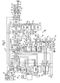
- Figure 1 shows the waveform producing circuitry 1 of an electronic musical instrument which is able selectively to generate played instrument musical sound waveforms such as those corresponding to the piano or the organ and rhythm instrument sound waveforms such as those corresponding to the drum or the cymbal, the particular instrument illustrated in Figure 1 being able to generate musical waveforms corresponding to eight musical and rhythmic instruments by means of eight channels in a time-sharing system.
- the sound waveform generating circuit 1 includes a waveform memory 2 in which waveform data for one basic cycle of each of several musical instrument sounds is stored, and a pitch forming circuit 3 the output Dl of which, comprising a maximum of eight channels of pitch data, is fed into the memory 2 in order to read out waveform data stored therein.
- the musical sound waveform generating circuit 1 as a musical sound waveform generating circuit for a played musical instrument, octave data input at D 2 a and note name data input at D b, composed by key data input at D 2 from a key board 4, is applied to a first pitch ROM (read only memory) 5, the input D 2 a being also fed into a first selector 6.
- the sound note name data D b is changed by the ROM 5 to data D 3 which has a pitch depending on the content of data D b and is applied to a second selector 7.
- a played instrument/rhythm instrument musical sound waveform switching signal LM is applied to the selectors 6 and 7.
- the output from the pitch forming circuit 3 is fed to the waveform memory 2 which provides musical sound waveform data (with a pitch determined by operation of a key) of a desired playing musical instrument in dependence upon musical instrument identification data input D 4 .
- the played instrument musical sound waveform data D 5 obtained as above described, is applied to a third selector 8 which is also controlled by the switching signal LM and,when the switching signal IM is of "O" level eight channels of musical sound waveform data D 5 are selectively applied to an envelope counter 9.
- a "key-on" signal S 1 , from a "key-on” detection circuit 10, together with a clock signal CLK are applied to the envelope counter 9 whereby an envelope representation of musical waveform data from the third selector 8 is obtained from 9 in response to input of the "key-on” signal S 1 .
- the musical note waveform data from 9 is applied to a D/A (digital-analog) converter 12 through a fourth selector 11, also controlled by the switching signal LM, and is changed to an analog musical note signal output S 2 .
- the analog musical note signal S 2 is fed to a low pass filter 13 to eliminate high noise frequency and thence via a level controlling circuit 14 and an adding circuit 15 to an amplifier 16 the output from which operates a loud-speaker 17.
- the musical sound waveform generating circuit 1 also includes a drum rhythm sound pitch data generating circuit 20 and a noise rhythm sound forming circuit 30 so as to be able to produce a drum rhythm musical sound waveform for cobel, highconga etc and noise rhythm musical sound waveform for cymbal, high-hat etc.
- the musical sound waveform generating circuit 1 is in the particular embodiment now being described, arranged to have a plurality of channels 0 to 7 in which respectively musical waveform treatment relating to a selected musical instrument is effected.
- channel assignment is as set out in the following Table 1.
- channels CH-O to CH-3 are assigned to noise musical instruments and channels CH-4 to CH-7 are assigned to drum musical instruments.
- the Snare Drum is treated by channel CH-3, and a repeated frequency thereof is treated by channel CH-4.
- Two kinds of musical instruments are assigned to each of the channels CE-4 and CH-5, but the two kinds are not such as to be required to be simultaneously employed, the Snare Drum being employed in Rock rhythm and the Crabes being employed in Latin rhythm.
- the cobel is employed in Samba rhythm, and the highconga is employed in rhythms other than the Samba rhythm.
- Designation of rhythm musical instruments is effected by operation of a rhythm musical instrument selection switch 18, three-bit data channels C O , C 1 and C 2 , which indicate a present channel and musical instrument code data lines SD/CL and CB/HC which determine which musical instruments are respectively assigned to the channels CH-4 and CH-5.
- the drum rhythm note pitch data generating circuit 20 produces a pitch data signal for reading out, by the pitch of a drum rhythm musical instrument, wave data which is stored in the memory 2.
- the said drum rhythm note pitch data generating circuit 20 has a read only memory (ROM) 21 to which musical instrument code data SD/CL, CB/HC and channel data C O and C 1 from the rhythm musical instrument selection switch 18 is applied.
- the ROM 21 produces assignment data D 6 for indicating an assigned rhythm musical instrument for each of the channels CH-4 to CH-7 and octave data D 7 for a rhythm musical instrument in each of the channels.
- the level of the switching signal LM becoes "1"
- the first selector 6 selectively produces rhythm instrument octave data D 7 (instead of played instrument octave data D 2 a) and applies said rhythm octave data D 7 to the pitch forming circuit 3.
- the level of the switching signal LM becomes "1” it inhibits the second selector 7 as regards the data D3.
- the data D B is applied as input signal to the second selector 7 and thence to the pitch forming circuit 3 only when the channel data C 2 level is "1".
- data DB from the second pitch ROM 22 is applied to the pitch forming circuit 3 through the second selector 7 when the channel data C 2 level is "1", as it is in the case of the drum rhythm musical instrument mode.
- the pitch forming circuit 3 is constructed as an eight channel dividing circuit and divides the clock signal CLK by said input data, generating a reading clock signal of preferably cyclic nature for the channels CH-4 to CH-7.
- Sine waveform data is read out from the memory 2 by a signal F when the musical sound waveform generating circuit 1 is operated so as to generate a rhythm musical sound waveform.
- sine wave data of preferred frequency determined for each of the channels CH-4 to CH-7, is generated from the memory 2.
- the output data from said memory 2 is thus a musical tone waveform data 8 a drum rhythm musical instrument sound.
- the third selector 8 applies waveform data selectively to the envelope counter 9 when the level of the switching signal LM is "1" and that of the channel data C 2 is “1", said waveform data, which is of waveform envelope form, being applied to the fourth selector 11.
- the said fourth selector 11 switches LM and C2and supplies data to an output line "A" only when the levels of LM and C 2 are both "1".
- musical sound waveform data of a drum rhythm musical instrument is applied to the low-pass filter 13 via the D/A converter 12, and thence via the level controller 14, adding circuit 15 and amplifier 16 to the loudspeaker 17.
- this provides noise rhythm sound waveforms in channels CH-O to CH-3 as set out in Table 1 and comprises a mixing circuit 38 which includes seven EX-OR gates 31 to 37 and a signal generator 39 for generating a plurality of signals for mixing in the mixing circuit 38.
- Said signal generator 39 which divides the clock signal CLK and generates eight different frequency signals P 1 to P 8 , is composed of dividers 40, 41, 42 and 43, for dividing the clock signal CLK in the ratios 36/1, 28/1, 8/1 and 2600/1 respectively, and the pitch forming circuit 3.
- the pitch forming circuit 3 comprises a dividing circuit, and the clock signal CLK is divided in accordance with a certain dividing ratio by using one of the channels CH-O to CH-3 of said pitch forming circuit 3, whereby it is able to produce different frequency signals for each channel.
- a four channel time-sharing dividing signal S 3 which is provided by the pitch forming circuit 3, is divided by a 1/2 divider 44 to form a signal with a 1/2 duty cycle which is applied to four latch circuits 45 to 48.
- Channel signals CSO to CS3, generated by decoding channel information D a by a decoder 19, are applied to the latch circuits 45 to 48 respectively and a signal from the 1/2 divider 44 is latched in at each channel timing, whereby signals P 1 to P 4 are produced as outputs from the respective latch circuits.
- the signals P5 to P8 are the outputs from the respective dividers 40 to 43.
- the frequencies of the signals Pl - P8 are best determined by experiment. In the particular embodiment now being described the frequencies of the signals P - P8 were selected from in the range 10 Hz to 50 KHz. These signals are mixed in the mixing circuit 38, to produce three mixed output signals O 1 , 0 2 and 0 3 which are added in an adder 49. This provides addition output data D 10 which is changed to log data D 11 by a log changing ROM 50 the output from which is applied to the selector 8.
- a maximum frequency becomes 1/8 of clock signal CLK it can not divide except a divide or integer/I.
- the highest frequency signal 0 is changed to log data D 12 by another log changing ROM 51 and is applied to the third selector 8.
- the data D 11 from the memory 50 is used as a cymbal sound waveform and the data D 12 from the memory 51 is used as snare drum noise.
- the third selector 8 selects data D 11 and D 12 instead of data from the memory 2 and feeds said data D 11 and D 12 into the envelope counter 9 which produces the corresponding envelope shape so that musical waveform data as shown in Table 1 is produced in the channels CH-O to CH-3.
- the fourth selector 11 produces output to the output line B when the switching signal LM level is "1" and the channel C 2 level is "O".
- the musical sound waveform data of a noise rhythm musical instrument is applied to a digital-analog (D/A) converter 60 which changes the data to an analog musical sound signal S 4 and this is applied via a level controller 61 to the adder 15 and thence to the amplifier 16 and loudspeaker 17.
- D/A digital-analog
- the fourth selector 11 separates the drum rhythm sound signal and the noise rhythm sound signal by making use of the fact that the noise rhythm sound signal is of relatively high frequency, 8000 - 10000 Hz, and will not pass a low-pass filter while the drum rhythm sound signal is composed of frequencies below about 2000Hz and will pass a low filter.
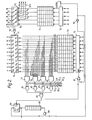
- Figure 2 shows one way of constructing the noise rhythm sound of waveform generating circuit by using the pitch forming circuit 3.
- the pitch forming circuit 3 comprises a 5 bit 8-channel shift register 70 and an adder 71 for adding output data from said shift register 70 to input data fed in at DIN. Output from the adder 71 is applied to the shift register 70 again via an AND-gate unit which is represented by block 72 and is controlled by an entry signal applied at ENTRY.
- the input data DIN is related to a certain dividing number which is determined by data input for the pitch forming circuit 3, and the addition resultant is affected by the value of the data DIN. Said addition resultant is returned to the AND-gate unit 72 and used as data for the timing of data reading from the memory 2, so that data is read out from the memory 2 in accordance with pitch data.
- the pitch forming circuit 3 has another dividing circuit arrangement comprising a 10-bit 8-channel shift register 73, an adder 74 for adding "1" or "0" from the shift register 73 in dependence upon the output from the adder 71 and an AND-gate unit 75 connected to the input of the shift register 73.
- the outputs from the adder 74 are applied to the AND-gate unit 75 as indicated by the letters F to O.
- This dividing circuit is able to divide the output of the adder 71 in the ratios 1/2, 1/4 and so on by the octave data, and said dividing circuit acts as a 1/2 divider when the output of the NAND-gate 76 becomes "1".
- the outputs from the AND-gates 81 to 84 are applied to an OR-gate 85, the output of which is directly applied to a 1-bit adder 86 and also, through a NOR-gate 87, to the inhibit terminal INH of the AND-gate unit 75.
- Each channel content of the register 73 is increased by 1 every cycle when the output level of the NOR-gate 76 is "1" and the +1 addition is repeated by the adder 74. Accordingly, the multi-input AND-gates 77 to 80 become of "1" level when the corresponding channel contents of the shift register 73 became of a certain value, so that the INH terminal becomes of "O" level in dependence on the opened AND-gate.
- the output from the adder 74 is not applied to the shift register 73, "O" level is set therein and the clock signal is divided in a time-sharing mode in the channels CH-O to CH-3.
- Pulses from the OR-gate 85 are sequentially stored in a 1-bit 8-channel shift register 88 via the 1-bit adder 86.
- the 1/2 dividing circuit 44 of Figure 1 is composed of the adder 86 and the shift register 88, whereby a divided signal of a certain frequency is produced in the channels CH-O to CH-3 in a timing mode.
- a 1/2 duty cycle is provided by the 1/2 dividing circuit 44 ( Figure 1).
- the entry signal at ENTRY is applied to the AND-gate unit 72 and to one input of an AND-gate 89, and the inverted entry signal ENTRY is applied to the remaining input of the NOR-gate 87.
- the outputs of the AND-gate unit 72 and of the shift register 70 become of "O" level when said entry signal becomes of "O” level.
- the input data contents DIN becomes "0"; and the output of the NOR-gate 76 becomes “1"; the contents of the shift registers 73 and 88 become “O”; and the pitch forming circuit 3 is accordingly reset. This operation produces the starting condition for when the entry signal is "1".
- an electronic musical instrument in accordance with the present invention a played musical instrument sound waveform generating function and a musical rhythm sound waveform generating function are provided and are easily selectable by a simple selecting operation. Furthermore the said two functions are carried out by a circuit construction (memory) which is used for both. Accordingly an electronic musical instrument in accordance with this invention has the advantage of being able to'be manufactured more simply and cheaply than a known comparable instrument as at present in general use.
Landscapes
- Engineering & Computer Science (AREA)
- Physics & Mathematics (AREA)
- Acoustics & Sound (AREA)
- Multimedia (AREA)
- General Engineering & Computer Science (AREA)
- Electrophonic Musical Instruments (AREA)
Applications Claiming Priority (2)
| Application Number | Priority Date | Filing Date | Title |
|---|---|---|---|
| JP57007894A JPS58125095A (ja) | 1982-01-21 | 1982-01-21 | 電子楽器用楽音波形発生回路 |
| JP7894/82 | 1982-01-21 |
Publications (2)
| Publication Number | Publication Date |
|---|---|
| EP0086047A2 true EP0086047A2 (de) | 1983-08-17 |
| EP0086047A3 EP0086047A3 (de) | 1985-10-16 |
Family
ID=11678283
Family Applications (1)
| Application Number | Title | Priority Date | Filing Date |
|---|---|---|---|
| EP83300286A Withdrawn EP0086047A3 (de) | 1982-01-21 | 1983-01-20 | Elektronisches Musikinstrument mit einem Wellenformspeicher |
Country Status (3)
| Country | Link |
|---|---|
| US (1) | US4515057A (de) |
| EP (1) | EP0086047A3 (de) |
| JP (1) | JPS58125095A (de) |
Cited By (2)
| Publication number | Priority date | Publication date | Assignee | Title |
|---|---|---|---|---|
| GB2251971A (en) * | 1988-03-03 | 1992-07-22 | Seiko Epson Corp | Sound synthesizer |
| US5179239A (en) * | 1988-03-03 | 1993-01-12 | Seiko Epson Corporation | Sound generating device for outputting sound signals having a sound waveform and an envelope waveform |
Families Citing this family (1)
| Publication number | Priority date | Publication date | Assignee | Title |
|---|---|---|---|---|
| JPH04166999A (ja) * | 1990-10-31 | 1992-06-12 | Seikosha Co Ltd | 音響信号合成回路 |
Family Cites Families (2)
| Publication number | Priority date | Publication date | Assignee | Title |
|---|---|---|---|---|
| US4178825A (en) * | 1977-06-06 | 1979-12-18 | Kawai Musical Instrument Mfg. Co. Ltd. | Musical tone synthesizer for generating a marimba effect |
| US4305319A (en) * | 1979-10-01 | 1981-12-15 | Linn Roger C | Modular drum generator |
-
1982
- 1982-01-21 JP JP57007894A patent/JPS58125095A/ja active Pending
-
1983
- 1983-01-17 US US06/458,477 patent/US4515057A/en not_active Expired - Fee Related
- 1983-01-20 EP EP83300286A patent/EP0086047A3/de not_active Withdrawn
Cited By (3)
| Publication number | Priority date | Publication date | Assignee | Title |
|---|---|---|---|---|
| GB2251971A (en) * | 1988-03-03 | 1992-07-22 | Seiko Epson Corp | Sound synthesizer |
| GB2251971B (en) * | 1988-03-03 | 1992-11-04 | Seiko Epson Corp | Sound synthesizer |
| US5179239A (en) * | 1988-03-03 | 1993-01-12 | Seiko Epson Corporation | Sound generating device for outputting sound signals having a sound waveform and an envelope waveform |
Also Published As
| Publication number | Publication date |
|---|---|
| US4515057A (en) | 1985-05-07 |
| JPS58125095A (ja) | 1983-07-25 |
| EP0086047A3 (de) | 1985-10-16 |
Similar Documents
| Publication | Publication Date | Title |
|---|---|---|
| US5119710A (en) | Musical tone generator | |
| US4184403A (en) | Method and apparatus for introducing dynamic transient voices in an electronic musical instrument | |
| US4361065A (en) | Integrated central processor for electronic organ | |
| US4624170A (en) | Electronic musical instrument with automatic accompaniment function | |
| JPH027078B2 (de) | ||
| US4342248A (en) | Orchestra chorus in an electronic musical instrument | |
| US4616547A (en) | Improviser circuit and technique for electronic musical instrument | |
| US5262581A (en) | Method and apparatus for reading selected waveform segments from memory | |
| US4208939A (en) | Data encoder for an electronic musical instrument | |
| EP0086047A2 (de) | Elektronisches Musikinstrument mit einem Wellenformspeicher | |
| US3764721A (en) | Electronic musical instrument | |
| US5498834A (en) | Electronic musical instrument capable of generating a resonance tone together with a musical tone | |
| US5221803A (en) | Tone signal generation from fewer circuits | |
| US4373415A (en) | Electronic musical instrument | |
| GB1384783A (en) | Orchestral effect producing system for an electronic musical instrument | |
| EP0039802B1 (de) | Elektronisches Musikinstrument | |
| GB1583626A (en) | Electronic musical instrument | |
| US4612839A (en) | Waveform data generating system | |
| US4561338A (en) | Automatic accompaniment apparatus | |
| US4319508A (en) | Modular, expandable digital organ system | |
| US4421001A (en) | Full note generator system for an electronic organ | |
| JPH0476480B2 (de) | ||
| US4216691A (en) | Octave assignment system for electronic musical instrument | |
| US4357851A (en) | Method and apparatus for producing mixture tones in an electronic musical instrument | |
| US10026386B2 (en) | Apparatus, method and computer program for memorizing timbres |
Legal Events
| Date | Code | Title | Description |
|---|---|---|---|
| PUAI | Public reference made under article 153(3) epc to a published international application that has entered the european phase |
Free format text: ORIGINAL CODE: 0009012 |
|
| AK | Designated contracting states |
Designated state(s): DE FR GB |
|
| PUAL | Search report despatched |
Free format text: ORIGINAL CODE: 0009013 |
|
| AK | Designated contracting states |
Designated state(s): DE FR GB |
|
| STAA | Information on the status of an ep patent application or granted ep patent |
Free format text: STATUS: THE APPLICATION IS DEEMED TO BE WITHDRAWN |
|
| 18D | Application deemed to be withdrawn |
Effective date: 19860617 |
|
| RIN1 | Information on inventor provided before grant (corrected) |
Inventor name: MOMOSHIMA, YUKICHI Inventor name: NAGASAKA, NABUYUKI |