EP0084947A2 - Bracing grids for nuclear reactor fuel sub-assemblies - Google Patents
Bracing grids for nuclear reactor fuel sub-assemblies Download PDFInfo
- Publication number
- EP0084947A2 EP0084947A2 EP83300223A EP83300223A EP0084947A2 EP 0084947 A2 EP0084947 A2 EP 0084947A2 EP 83300223 A EP83300223 A EP 83300223A EP 83300223 A EP83300223 A EP 83300223A EP 0084947 A2 EP0084947 A2 EP 0084947A2
- Authority
- EP
- European Patent Office
- Prior art keywords
- sub
- assembly
- grids
- joggled
- grid
- Prior art date
- Legal status (The legal status is an assumption and is not a legal conclusion. Google has not performed a legal analysis and makes no representation as to the accuracy of the status listed.)
- Granted
Links
- 239000003758 nuclear fuel Substances 0.000 title claims description 4
- 238000000429 assembly Methods 0.000 title description 3
- 239000000446 fuel Substances 0.000 claims abstract description 13
- 239000000463 material Substances 0.000 claims description 3
- 229910003460 diamond Inorganic materials 0.000 claims description 2
- 239000010432 diamond Substances 0.000 claims description 2
- 238000010276 construction Methods 0.000 description 3
- 239000002184 metal Substances 0.000 description 3
- 239000002826 coolant Substances 0.000 description 2
- 239000012634 fragment Substances 0.000 description 2
- 230000013011 mating Effects 0.000 description 1
- 230000002441 reversible effect Effects 0.000 description 1
- 239000002699 waste material Substances 0.000 description 1
Images

Classifications
-
- G—PHYSICS
- G21—NUCLEAR PHYSICS; NUCLEAR ENGINEERING
- G21C—NUCLEAR REACTORS
- G21C3/00—Reactor fuel elements and their assemblies; Selection of substances for use as reactor fuel elements
- G21C3/30—Assemblies of a number of fuel elements in the form of a rigid unit
- G21C3/32—Bundles of parallel pin-, rod-, or tube-shaped fuel elements
- G21C3/34—Spacer grids
- G21C3/348—Spacer grids formed of assembled non-intersecting strips
-
- Y—GENERAL TAGGING OF NEW TECHNOLOGICAL DEVELOPMENTS; GENERAL TAGGING OF CROSS-SECTIONAL TECHNOLOGIES SPANNING OVER SEVERAL SECTIONS OF THE IPC; TECHNICAL SUBJECTS COVERED BY FORMER USPC CROSS-REFERENCE ART COLLECTIONS [XRACs] AND DIGESTS
- Y02—TECHNOLOGIES OR APPLICATIONS FOR MITIGATION OR ADAPTATION AGAINST CLIMATE CHANGE
- Y02E—REDUCTION OF GREENHOUSE GAS [GHG] EMISSIONS, RELATED TO ENERGY GENERATION, TRANSMISSION OR DISTRIBUTION
- Y02E30/00—Energy generation of nuclear origin
- Y02E30/30—Nuclear fission reactors
Definitions
- This invention relates to bracing grids for fuel pins in nuclear reactor fuel sub-assemblies and is concerned with such grids for highly rated fuel pins as used in fast reactors.
- GB-PS 1,052,777 shows a grid having dimpled circular tubes to define unit cells to locate fuel pins and also has other non-circular un-dimpled tubes mating with the circular tubes to space them apart. This is a complicated structure, it has low compliance, it requires a multiplicity of tube sections and it is time consuming and costly to fabricate. In any event the pin locating unit cells are not closely spaced, and cannot be closely spaced, as required by the high rating of fast reactors.
- a single level, dimpled, joggled strip form of grid has however been used in which the cells in the grid are defined by strip material confined to a single level.
- the grid has edge cells which are formed in part by the joggled strips and in part by shaped supplementary strips.
- This grid has an inherent mechanical weakness and constructional problems which the present invention seeks to overcome whilst still retaining the advantages which are inherent with joggled strip.
- the present invention provides a nuclear reactor fuel sub-assembly comprising a bundle of spaced fuel pins within a tubular wrapper having a series of bracing grids each formed with dimpled joggled strip at a single level disposed at intervals along the sub-assembly characterised in that the peripheries of the grids are completed by unit edge cells.
- FIG 1 and 1A a series of dimpled joggle strips 10 are shown assembled together to form the main construction of a compliant bracing grid.
- the edge sells 11 of the grids each have six walls.
- four of the walls are formed by the ends of joggled strips 10 and two are formed by a shaped supplementary strip 12 having ends 12a and 12b which lie alongside the ends of a strip 10.
- this construction gives rise to a spot weld 14 which has to penetrate and join together three thickness of metal and, in the case of end 12b, the weld is made very near the extremity in order to accommodate a fuel pin locating dimple 13. This is an inherently weak joint and not easy to inspect.
- a faulty joint can create one or other of two very costly Situations. If the faulty weld is discovered before the grid is used the whole grid is waste. If the faulty weld is discovered in use then a complete fuel assembly has to be discharged from a reactor.
- the weld strength of the edge cell is derived from two "triple-layer” welds 13 and two "double-layer” welds 15.
- the axial strength of the grid is also weakened by the form of weld 14 shown when compared with welds like weld 15 which exist elsewhere in the grid.
- the grids are subjected to substantial doming forces by axial coolant flow and by thermal dimension changes in fuel pins in frictional contact with the dimples of the grid.
- For a dome to be strong it is essential that its base perimeter is strong.
- the supplementary strip 12 and welds 14 do not provide such strength.
- a grid 27 is shown having dimpled joggled strip 20 completed at its periphery by unit cells 21. It is seen that the weld strength of each cell 21 is derived from eight "double-layer” welds 25 and "triple-layer” welds are avoided altogether. In addition the cells 21 are much stronger than supplementary strips 12 of Figure 1.
- the cells of the grids have dimples 23 to centralise fuel pins 26 in the cells.
- the dimples are of elongate diamond shape and disposed with their longitudinal axes parallel with the axes of the cells so that turbulance and pressure drop through the cells are minimised. This shape also reduces metal thinning when forming the dimples as metal pulled from the strip to form the dimples is drawn from a greater area. Typically there could be 325 fuel pins 26 located by the grid.
- Figure 3 shows the construction of the grid at the corner posts 30.
- each grid has six clip parts 31 to clip the grid to the cut aways 30a of six posts 30.
- the clip parts 31 have flaps 32 which can be deflected into cut aways 30a to locate the grids on the posts 30.
- the clip parts 31 are filled with a bolster 33 which is edge welded to the flaps 32 at 34.
- the bolster 33 forms a small clearance 35 with the part 30b. This gives"a small degree of freedom in the whole assembly.
- An approximately hexagonal tubular wrapper 36 is shown.
- unit cells 21 exist all round the periphery of the grid, even at the posts 30, and hence the continuity of the strength giving edge cells is maintained.
- the cells 21 could be of unjoined section but it is convenient to form them with a small opening 21a using the same stock material as is used for the joggled strips 20.
- Figure 1 grid requires a greater variety of joggled strips as in Figure 1 some of the strips terminate at "long" ends and others at “short” ends and they are not reversible.
- Figure 2 grid uses about 40% less varieties of joggled strip.
Landscapes
- Physics & Mathematics (AREA)
- Engineering & Computer Science (AREA)
- Plasma & Fusion (AREA)
- General Engineering & Computer Science (AREA)
- High Energy & Nuclear Physics (AREA)
- Fuel Cell (AREA)
- Pressure Welding/Diffusion-Bonding (AREA)
- Monitoring And Testing Of Nuclear Reactors (AREA)
- Supports For Pipes And Cables (AREA)
Abstract
Description
- This invention relates to bracing grids for fuel pins in nuclear reactor fuel sub-assemblies and is concerned with such grids for highly rated fuel pins as used in fast reactors.
- The use and development of bracing grids in fuel sub-assemblies goes back over a long period. For example GB-PS 1,052,777 shows a grid having dimpled circular tubes to define unit cells to locate fuel pins and also has other non-circular un-dimpled tubes mating with the circular tubes to space them apart. This is a complicated structure, it has low compliance, it requires a multiplicity of tube sections and it is time consuming and costly to fabricate. In any event the pin locating unit cells are not closely spaced, and cannot be closely spaced, as required by the high rating of fast reactors.
- In a further prior art disclosure, namely GB-PS 1,386,424 the concept of a "joggled" strip grid is introduced. The strip, in the course of its length, defines the dimpled walls of many cells but never itself defines a complete unit cell. Each cell in the grid is defined by a second level of joggled strips which cooperate with those in the first level. This introduces complexity and problems of matching two sets of strips at different levels with the dimples correctly placed and each set of strips introduces entry and exit power losses in the flow of coolant through the grids.
- A single level, dimpled, joggled strip form of grid has however been used in which the cells in the grid are defined by strip material confined to a single level. There has been no known publication of this grid and accordingly it is described below with reference to the drawings. As described, the grid has edge cells which are formed in part by the joggled strips and in part by shaped supplementary strips. This grid has an inherent mechanical weakness and constructional problems which the present invention seeks to overcome whilst still retaining the advantages which are inherent with joggled strip.
- To this end the present invention provides a nuclear reactor fuel sub-assembly comprising a bundle of spaced fuel pins within a tubular wrapper having a series of bracing grids each formed with dimpled joggled strip at a single level disposed at intervals along the sub-assembly characterised in that the peripheries of the grids are completed by unit edge cells.
- The invention will now be described further with reference to the accompanying drawings in which:
- Figure 1 shows in plan view a fragment of a single level, dimpled, joggled strip grid as already used, with Figure 1A providing a magnified view of a part of the grid;
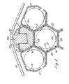
- Figure 2 shows in plan view a fragment of a single level, dimpled, joggled strip grid for use in a sub-assembly according to the invention; and
- Figure 3 shows the grid of Figure 2 at a corner post of the sub-assembly.
- In Figure 1 and 1A (prior art) a series of
dimpled joggle strips 10 are shown assembled together to form the main construction of a compliant bracing grid. The edge sells 11 of the grids each have six walls. For any edge cell, four of the walls are formed by the ends ofjoggled strips 10 and two are formed by a shapedsupplementary strip 12 having ends 12a and 12b which lie alongside the ends of astrip 10. As seen clearly in Figure 1A this construction gives rise to a spot weld 14 which has to penetrate and join together three thickness of metal and, in the case of end 12b, the weld is made very near the extremity in order to accommodate a fuelpin locating dimple 13. This is an inherently weak joint and not easy to inspect. A faulty joint can create one or other of two very costly Situations. If the faulty weld is discovered before the grid is used the whole grid is waste. If the faulty weld is discovered in use then a complete fuel assembly has to be discharged from a reactor. The weld strength of the edge cell is derived from two "triple-layer"welds 13 and two "double-layer" welds 15. - The axial strength of the grid is also weakened by the form of weld 14 shown when compared with welds like weld 15 which exist elsewhere in the grid. The grids are subjected to substantial doming forces by axial coolant flow and by thermal dimension changes in fuel pins in frictional contact with the dimples of the grid. For a dome to be strong it is essential that its base perimeter is strong. The
supplementary strip 12 and welds 14 do not provide such strength. - In Figure 2 a
grid 27 is shown havingdimpled joggled strip 20 completed at its periphery byunit cells 21. It is seen that the weld strength of eachcell 21 is derived from eight "double-layer"welds 25 and "triple-layer" welds are avoided altogether. In addition thecells 21 are much stronger thansupplementary strips 12 of Figure 1. The cells of the grids have dimples 23 to centralisefuel pins 26 in the cells. The dimples are of elongate diamond shape and disposed with their longitudinal axes parallel with the axes of the cells so that turbulance and pressure drop through the cells are minimised. This shape also reduces metal thinning when forming the dimples as metal pulled from the strip to form the dimples is drawn from a greater area. Typically there could be 325fuel pins 26 located by the grid. - Figure 3 shows the construction of the grid at the
corner posts 30. - At the length of the
post 30 occupied by the grid shown, thepost 30 is cut away at 30a to leave only arectangular section part 30b. Each grid has sixclip parts 31 to clip the grid to the cutaways 30a of sixposts 30. Theclip parts 31 haveflaps 32 which can be deflected into cutaways 30a to locate the grids on theposts 30. Theclip parts 31 are filled with abolster 33 which is edge welded to theflaps 32 at 34. Thebolster 33 forms a small clearance 35 with thepart 30b. This gives"a small degree of freedom in the whole assembly. - An approximately hexagonal
tubular wrapper 36 is shown. - It is seen that the
unit cells 21 exist all round the periphery of the grid, even at theposts 30, and hence the continuity of the strength giving edge cells is maintained. - The
cells 21 could be of unjoined section but it is convenient to form them with asmall opening 21a using the same stock material as is used for thejoggled strips 20. - Another merit may arise from the invention when the grid of Figure 2 is compared with that of Figure 1. The Figure 1 grid requires a greater variety of joggled strips as in Figure 1 some of the strips terminate at "long" ends and others at "short" ends and they are not reversible. The Figure 2 grid on the other hand uses about 40% less varieties of joggled strip.
Claims (5)
Applications Claiming Priority (2)
| Application Number | Priority Date | Filing Date | Title |
|---|---|---|---|
| GB8201577 | 1982-01-20 | ||
| GB08201577A GB2113900B (en) | 1982-01-20 | 1982-01-20 | Bracing grids for nuclear reactor fuel sub-assemblies |
Publications (3)
| Publication Number | Publication Date |
|---|---|
| EP0084947A2 true EP0084947A2 (en) | 1983-08-03 |
| EP0084947A3 EP0084947A3 (en) | 1984-04-25 |
| EP0084947B1 EP0084947B1 (en) | 1987-11-25 |
Family
ID=10527743
Family Applications (1)
| Application Number | Title | Priority Date | Filing Date |
|---|---|---|---|
| EP83300223A Expired EP0084947B1 (en) | 1982-01-20 | 1983-01-18 | Bracing grids for nuclear reactor fuel sub-assemblies |
Country Status (5)
| Country | Link |
|---|---|
| US (1) | US4568512A (en) |
| EP (1) | EP0084947B1 (en) |
| JP (1) | JPS58124986A (en) |
| DE (1) | DE3374736D1 (en) |
| GB (1) | GB2113900B (en) |
Cited By (1)
| Publication number | Priority date | Publication date | Assignee | Title |
|---|---|---|---|---|
| FR2560422A1 (en) * | 1984-02-28 | 1985-08-30 | Atomic Energy Authority Uk | COMBUSTIBLE ASSEMBLIES FOR NUCLEAR REACTOR |
Families Citing this family (4)
| Publication number | Priority date | Publication date | Assignee | Title |
|---|---|---|---|---|
| EP0210526B1 (en) * | 1985-07-24 | 1989-05-24 | Siemens Aktiengesellschaft | Nuclear-fuel assembly |
| DE4410396A1 (en) * | 1994-03-25 | 1995-09-28 | Siemens Ag | Spacers with hexagonal mesh |
| US5519747A (en) * | 1994-10-04 | 1996-05-21 | General Electric Company | Apparatus and methods for fabricating spacers for a nuclear fuel rod bundle |
| JP4559965B2 (en) * | 2005-12-27 | 2010-10-13 | 株式会社東芝 | Nuclear fuel assembly |
Citations (5)
| Publication number | Priority date | Publication date | Assignee | Title |
|---|---|---|---|---|
| GB1052777A (en) * | 1900-01-01 | |||
| GB1206579A (en) * | 1968-09-12 | 1970-09-23 | Westinghouse Electric Corp | Nuclear reactor fuel assembly |
| US3646994A (en) * | 1969-12-23 | 1972-03-07 | Reactor Centrum Nederland | Spacer grid respectively plate spring for a bunch of cylindrical elements taking part in a heat-exchanging process |
| GB1386424A (en) * | 1972-03-15 | 1975-03-05 | Atomic Energy Authority Uk | Locating grids |
| GB2011150A (en) * | 1977-09-09 | 1979-07-04 | Atomic Energy Authority Uk | Nuclear reactors |
-
1982
- 1982-01-20 GB GB08201577A patent/GB2113900B/en not_active Expired
-
1983
- 1983-01-10 US US06/456,710 patent/US4568512A/en not_active Expired - Fee Related
- 1983-01-18 EP EP83300223A patent/EP0084947B1/en not_active Expired
- 1983-01-18 DE DE8383300223T patent/DE3374736D1/en not_active Expired
- 1983-01-19 JP JP58007205A patent/JPS58124986A/en active Pending
Patent Citations (5)
| Publication number | Priority date | Publication date | Assignee | Title |
|---|---|---|---|---|
| GB1052777A (en) * | 1900-01-01 | |||
| GB1206579A (en) * | 1968-09-12 | 1970-09-23 | Westinghouse Electric Corp | Nuclear reactor fuel assembly |
| US3646994A (en) * | 1969-12-23 | 1972-03-07 | Reactor Centrum Nederland | Spacer grid respectively plate spring for a bunch of cylindrical elements taking part in a heat-exchanging process |
| GB1386424A (en) * | 1972-03-15 | 1975-03-05 | Atomic Energy Authority Uk | Locating grids |
| GB2011150A (en) * | 1977-09-09 | 1979-07-04 | Atomic Energy Authority Uk | Nuclear reactors |
Cited By (1)
| Publication number | Priority date | Publication date | Assignee | Title |
|---|---|---|---|---|
| FR2560422A1 (en) * | 1984-02-28 | 1985-08-30 | Atomic Energy Authority Uk | COMBUSTIBLE ASSEMBLIES FOR NUCLEAR REACTOR |
Also Published As
| Publication number | Publication date |
|---|---|
| GB2113900B (en) | 1985-11-20 |
| EP0084947B1 (en) | 1987-11-25 |
| US4568512A (en) | 1986-02-04 |
| GB2113900A (en) | 1983-08-10 |
| DE3374736D1 (en) | 1988-01-07 |
| EP0084947A3 (en) | 1984-04-25 |
| JPS58124986A (en) | 1983-07-25 |
Similar Documents
| Publication | Publication Date | Title |
|---|---|---|
| EP0291748B1 (en) | Support grid with integral vanes | |
| US4714585A (en) | Interlocking egg-crate type grid assembly | |
| JP2521002B2 (en) | Swirl vanes for addition to spring metal grid spacers and methods of adding swirl vanes to spring metal grid spacers | |
| US4923669A (en) | Nuclear fuel rod grid spring and dimple structures having chamfered edges for reduced pressure drop | |
| US6421407B1 (en) | Nuclear fuel spacer grid with dipper vanes | |
| JP3605171B2 (en) | Reactor fuel assembly | |
| US4312705A (en) | Spacer for nuclear reactor fuel assemblies | |
| US5024810A (en) | Support grid with integral inclined waves | |
| US4125435A (en) | Grid lattice with sliding strap | |
| US5282233A (en) | Low pressure drop easy load end cap | |
| EP3686900B1 (en) | Positioning grid and fuel assembly | |
| US3920516A (en) | Nuclear reactor fuel assembly arrangement | |
| JPH01167696A (en) | Spring structure of fuel rod grid | |
| US4728489A (en) | Support grid with integral vanes | |
| US4775509A (en) | Spacer grid for a nuclear fuel assembly | |
| US5173252A (en) | Removable springs for ferrule spacer | |
| US4568512A (en) | Bracing grids for nuclear reactor fuel sub-assemblies | |
| US3890196A (en) | Nuclear reactor fuel element assembly spacer grid and method of making | |
| US4556531A (en) | Nuclear fuel assembly spacer and spring component therefor | |
| US5546437A (en) | Spacer for nuclear fuel rods | |
| US4028180A (en) | Support grid for fuel elements in a nuclear reactor | |
| US4163690A (en) | Nuclear reactor fuel assembly spacer grid | |
| US5859887A (en) | Nuclear fuel assembly support grid | |
| US4351795A (en) | Grids for nuclear fuel assemblies | |
| US6714619B2 (en) | Spacer grid with double deflected vanes for nuclear fuel assemblies |
Legal Events
| Date | Code | Title | Description |
|---|---|---|---|
| PUAI | Public reference made under article 153(3) epc to a published international application that has entered the european phase |
Free format text: ORIGINAL CODE: 0009012 |
|
| AK | Designated contracting states |
Designated state(s): DE FR GB IT |
|
| PUAL | Search report despatched |
Free format text: ORIGINAL CODE: 0009013 |
|
| AK | Designated contracting states |
Designated state(s): DE FR GB IT |
|
| 17P | Request for examination filed |
Effective date: 19840626 |
|
| GRAA | (expected) grant |
Free format text: ORIGINAL CODE: 0009210 |
|
| AK | Designated contracting states |
Kind code of ref document: B1 Designated state(s): DE FR GB IT |
|
| ITF | It: translation for a ep patent filed | ||
| REF | Corresponds to: |
Ref document number: 3374736 Country of ref document: DE Date of ref document: 19880107 |
|
| ET | Fr: translation filed | ||
| PLBE | No opposition filed within time limit |
Free format text: ORIGINAL CODE: 0009261 |
|
| STAA | Information on the status of an ep patent application or granted ep patent |
Free format text: STATUS: NO OPPOSITION FILED WITHIN TIME LIMIT |
|
| 26N | No opposition filed | ||
| ITTA | It: last paid annual fee | ||
| PGFP | Annual fee paid to national office [announced via postgrant information from national office to epo] |
Ref country code: GB Payment date: 19901212 Year of fee payment: 9 |
|
| PGFP | Annual fee paid to national office [announced via postgrant information from national office to epo] |
Ref country code: DE Payment date: 19901221 Year of fee payment: 9 |
|
| PGFP | Annual fee paid to national office [announced via postgrant information from national office to epo] |
Ref country code: FR Payment date: 19910104 Year of fee payment: 9 |
|
| PG25 | Lapsed in a contracting state [announced via postgrant information from national office to epo] |
Ref country code: GB Effective date: 19920118 |
|
| REG | Reference to a national code |
Ref country code: GB Ref legal event code: PCNP |
|
| PG25 | Lapsed in a contracting state [announced via postgrant information from national office to epo] |
Ref country code: FR Effective date: 19920930 |
|
| PG25 | Lapsed in a contracting state [announced via postgrant information from national office to epo] |
Ref country code: DE Effective date: 19921001 |
|
| REG | Reference to a national code |
Ref country code: FR Ref legal event code: ST |