EP0084005A1 - Appareil de désilage - Google Patents
Appareil de désilage Download PDFInfo
- Publication number
- EP0084005A1 EP0084005A1 EP83400027A EP83400027A EP0084005A1 EP 0084005 A1 EP0084005 A1 EP 0084005A1 EP 83400027 A EP83400027 A EP 83400027A EP 83400027 A EP83400027 A EP 83400027A EP 0084005 A1 EP0084005 A1 EP 0084005A1
- Authority
- EP
- European Patent Office
- Prior art keywords
- tool
- disc
- silo
- radial arm
- discs
- Prior art date
- Legal status (The legal status is an assumption and is not a legal conclusion. Google has not performed a legal analysis and makes no representation as to the accuracy of the status listed.)
- Withdrawn
Links
- 239000004460 silage Substances 0.000 title claims abstract description 22
- 238000000605 extraction Methods 0.000 title abstract 3
- 239000000463 material Substances 0.000 claims abstract description 24
- 230000007423 decrease Effects 0.000 claims description 3
- 125000006850 spacer group Chemical group 0.000 claims description 3
- 238000006073 displacement reaction Methods 0.000 abstract 1
- 239000011368 organic material Substances 0.000 abstract 1
- 238000004519 manufacturing process Methods 0.000 description 4
- 230000001154 acute effect Effects 0.000 description 3
- 230000015556 catabolic process Effects 0.000 description 3
- 238000004140 cleaning Methods 0.000 description 3
- 238000010276 construction Methods 0.000 description 3
- 238000012423 maintenance Methods 0.000 description 3
- 230000007246 mechanism Effects 0.000 description 3
- 239000000428 dust Substances 0.000 description 2
- 238000007790 scraping Methods 0.000 description 2
- 229910000831 Steel Inorganic materials 0.000 description 1
- 230000008901 benefit Effects 0.000 description 1
- 230000000903 blocking effect Effects 0.000 description 1
- 239000000969 carrier Substances 0.000 description 1
- 239000003638 chemical reducing agent Substances 0.000 description 1
- 239000013013 elastic material Substances 0.000 description 1
- 238000005265 energy consumption Methods 0.000 description 1
- 230000030279 gene silencing Effects 0.000 description 1
- 239000002184 metal Substances 0.000 description 1
- 230000004048 modification Effects 0.000 description 1
- 238000012986 modification Methods 0.000 description 1
- 239000005416 organic matter Substances 0.000 description 1
- 230000009467 reduction Effects 0.000 description 1
- 230000008439 repair process Effects 0.000 description 1
- 239000010959 steel Substances 0.000 description 1
Images

Classifications
-
- A—HUMAN NECESSITIES
- A01—AGRICULTURE; FORESTRY; ANIMAL HUSBANDRY; HUNTING; TRAPPING; FISHING
- A01F—PROCESSING OF HARVESTED PRODUCE; HAY OR STRAW PRESSES; DEVICES FOR STORING AGRICULTURAL OR HORTICULTURAL PRODUCE
- A01F25/00—Storing agricultural or horticultural produce; Hanging-up harvested fruit
- A01F25/16—Arrangements in forage silos
- A01F25/20—Unloading arrangements
- A01F25/2009—Top unloading units for tower silos
Definitions
- the silencing apparatus comprises disc-tools which are rotated autonomously, which are provided with knives. on their front face and which are slightly inclined relative to the radial arm, their inclination on this arm preferably being between 0 ° and 20 ° and, advantageously, close to 10 °.
- the unloading apparatus can comprise a motor mounted at one end of the radial arm, a V-belt or a set of such belts connecting the shaft of this engine to a pulley secured to the disc-tool shaft closest to the end of the radial arm where the engine is installed, wheels toothed wedges on the shafts of the various tool discs of the roller chains, each of which connects one of these shafts to the next by means of toothed wheels wedged on the shafts, and at least one idler sprocket per chain to ensure the tension the corresponding string.
- this device allows the cleaning of the silo wall by scraping by means of the elastic fins of the impeller, as well as the desilage of the materials in the vicinity of this wall thanks to the cutting tool mounted on the underside of this wheel.
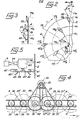
- the unloading device is mounted inside a silo 1 with a cylindrical wall 2, and it essentially comprises a radial arm 3 on which are mounted several tool discs 4a, 4b ... 4n.
- guide wheels 9 and 9 ′ with vertical axis are also mounted on the arm 3 in the vicinity of the wall 2 of the silo 1, one of them, 9, being located at the outer end of the arm 3, and the other, 9 ′, associated with a load wheel 9 ", being very much offset from the previous one.
- the load wheels 6 and 9" the wheels carriers and drive 8, the drive motor associated with each of these, and the guide wheels 9 and 9 'allow the radial arm 3 to rotate autonomously around the vertical axis 5 of the silo while remaining substantially parallel to the free surface of the material to be desiled on which it rests by the pairs of wheels 6 and 8 and by the wheel 9 ".
- the arm 3 also comprises, in the vicinity of the axis 5 of the silo 1, a fan 10 with a horizontal motor 11 which ensures, by means of pipes not shown, the evacuation of the desilated materials, these materials being brought towards the center of the silo by the actual silage removal device which will now be described.
- the tool discs 4a ... 4n are mounted in front of the arm 3, taking into account its direction of rotation indicated in FIG. 1 by the arrow F. They are substantially vertical and they are fixed by their centers at the end of shafts 12a ... 12n, which are perpendicular to the discs and of which they are integral. These shafts 12 are all mutually parallel and they are mounted mobile in rotation in bearings which are respectively designated by the references 13a .... 13n., And which are mounted on the upper face of the radial arm 3 by means of plates- supports 14a ... 14n, welded to this arm 3.
- the shafts 12 form an angle ⁇ with the horizontal straight lines of direction X which are perpendicular to the arm 3, the direction of this angle ⁇ being such that the tool discs 4 which, of course, form the same angle ⁇ with the arm 3, are inclined outward.
- each tool disc 4 - is offset by the same distance from the previous one in the direction of the shafts 12.
- the plane of each disc, except that of the end discs, is interposed between the previous and the next.
- the arm 3 is constituted by a steel section with square section of 150 mm side, and it supports ten discs 4 whose diameter is 600 or 650 mm and whose thickness is 4 to 5 mm or more.
- the angle oC is equal to 10 ° and the distance d between two consecutive bearings is 400 mm. Arm 3 rotates at a rate of approximately 90 ° / min.
- Each disc-tool 4 is provided on its front face, in the direction of rotation of the radial arm 3 indicated by the arrow F, with a plurality of cutting tools, only one of which has been shown for each disc in FIG. 1 where it carries the mark 15a for the disk 4a, the mark 15b for the disk 4b, and so on.
- Each disc-tool 4 is provided with several series of tools, the various tools of the same series being arranged at different distances from the center of the disc.
- each tool disc 4 comprises four series of three tools distributed over three circles 16a, 16b and 16c which are centered all three on the center of the disc, the distance between the internal circles 16c and median 16b being approximately equal to the distance between the median circles 16b and external 16a, and the latter being practically coincident with the periphery of the disc-tool 4.
- the tools are regularly distributed around the disc 4, which means that they are located on spokes 17a, 17b, etc., of this disc which share it in equal sectors, and this, at a rate of tool by radius.
- the height of the rectangular plate 19 decreases from the inner circle 16c to the outer circle 16a, and the height of the plate which is the outermost, therefore on the circle 16a , may be substantially zero, so that the corresponding tool boils down to its inclined part 30 which is welded to the edge of the disc 4 extending towards the outside of the latter.
- discs 4 were used comprising four series of three tools which are therefore spaced angularly by 30 °, as has already been indicated.
- the angles ⁇ and b were respectively equal to 30 ° and 28 °, the real acute angle ⁇ of the parallelogram 20 being by construction of approximately 45 °.
- the height of each welded rectangular plate 19, taken perpendicular to the plane of the disc 4, was 40 or 50 mm for the tools located in the vicinity of the inner circle 16c, approximately half for the tools mounted near the middle circle 16b, and substantially zero for tools welded to the periphery of disc 4.
- the radial distance between tools in the same series was approximately 30 mm. In this way, "steps" are cut in the material to be desiled, the height of which is 30 mm and the width of 20 or 25 mm.
- a pulley 25 mounted on the motor shaft 23 drives the shafts 26 and 27 of the two nearest tool discs by means of two sets of V-belts 28 and, respectively, 29, and pulleys 26 'and 27' secured respectively to shafts 26 and 27.
- the motor 23 is mounted at an equal distance from the two shafts 26 and 27.
- the shafts 26 and 27 that the other tool discs are driven in rotation by means of roller chains.
- the shaft 26 which will be assumed to be closer to the axis of the silo than the shaft 27 carries a toothed wheel 30 which, by means of a roller chain 31, rotates a driven toothed wheel 32 secured to the shaft 33 of the immediately following tool disc in the direction towards the inside of the silo.
- This shaft 33 is also integral with a driving gear 33 '(see also Figure 1) which meshes with another roller chain 34, which in turn meshes with a driven wheel wedged on the following shaft 35, and thus immediately to the tool disc closest to the axis of the silo.
- the shaft 27 carries a toothed wheel 36 which drives a wheel 37 wedged on the shaft of the next tool disc by means of a roller chain 38.
- a wheel leading gear 37 'wedged on the same shaft as the driven gear 37 meshes with another chain 38' which drives the next shaft, and so on to the tool disc closest to the wall 2 of the silo.
- the shaft of each tool disc is provided with a driving toothed wheel and a driven toothed wheel, with the exception of the central shafts 26 and 27 provided only of a driving wheel, and of the extreme trees which comprise only one driven wheel.
- the tension of the roller chains is ensured, in a conventional manner, by idler sprockets which are not shown, at the rate of at least one idler sprocket per chain.
- the drive of the shafts 26 and 27 from the motor 23 can be achieved by means of belts, which is advantageous from the point of view; economic. In fact, these belts, because of their high linear running speed, are not affected by the dust resulting from the unloading operation. There is none not the same, of course, for the connections between the various shafts of the tool discs, which must be provided by chain drives.
- the motor 23 has a power of 10 CV and it rotates with a rotation speed of between 1,350 and 1,500 revolutions per minute.
- its pulley 25 With a diameter equal to 100 mm drives the pulleys 26 'and 27' secured to the shafts 26 and 27, pulleys whose diameter is 500 mm.
- the speed of rotation of the tool discs 4 taking into account this reduction ratio, is then between 270 and 300 revolutions per minute.
- the unloading device may further comprise means for cleaning by scraping the wall of the silo at the level of the radial arm 3 and for carrying out the unloading in the vicinity of this wall, these operations being carried out at the same time as the unloading of the interior of the silo which is done as just described.
- These means comprise a wheel 39 with a vertical axis 40 (see FIG. 5) provided with elastic fins 41 and mounted at the end of the radial arm 3 which is adjacent to the wall 2 of the silo.
- the fins 41 extend horizontally towards the outside of the wheel 39, projecting beyond the periphery of this wheel, and they are made of an elastic material such as rubber or a suitable plastic material.
- they are made integral with the wheel 39 by any suitable means such as, for example, by bolting on lugs 42 welded to the wheel 39.
- the assembly constituted by the wheel 39 and the fins 41 is driven in rotation autonomously in the same direction as the radial arm 3 by means of a motor 43 with axis vertical, which is connected to the axis 40 of the wheel 39 by the inter ediate m of a reducing agent.
- This motor 43 is made integral with the radial arm 3 by a linkage shown diagrammatically at 44 which comprises an elastic return device not shown and which presses the fins 41 of the wheel 39 on the wall of the silo.
- a spacer wheel 45 fixed for example on the motor 43 or on the linkage 44 determines the minimum distance between the axis 40 of the wheel 39 and the wall 2 of the silo, and it thus avoids any contact between the wheel 39 proper and the silo wall. It is therefore the elastic fins 41, and only they, which scrape this wall to clean it.
- tools 46 similar to the tools 15 of the tool discs 4 of FIG. 1 can be mounted on the underside of the wheel 39 to unstack the layer of material in the vicinity of the wall 2 of the silo.
- the diameter of the wheel 39 can be of the order of 200 to 300 mm, or about half that of the tool discs 4, its speed of rotation being for example close to 300 rpm .
- a motor 43 with a power of 1.5 CV is perfectly suitable for driving the wheel 39 in rotation.
- the latter can comprise four fins regularly distributed around its periphery and it can be provided with four tools 46 at the periphery of its lower face.
Landscapes
- Life Sciences & Earth Sciences (AREA)
- Environmental Sciences (AREA)
- Filling Or Emptying Of Bunkers, Hoppers, And Tanks (AREA)
- Adjustment And Processing Of Grains (AREA)
Applications Claiming Priority (2)
| Application Number | Priority Date | Filing Date | Title |
|---|---|---|---|
| FR8200084A FR2519231A1 (fr) | 1982-01-06 | 1982-01-06 | Appareil de desilage |
| FR8200084 | 1982-01-06 |
Publications (1)
| Publication Number | Publication Date |
|---|---|
| EP0084005A1 true EP0084005A1 (fr) | 1983-07-20 |
Family
ID=9269732
Family Applications (1)
| Application Number | Title | Priority Date | Filing Date |
|---|---|---|---|
| EP83400027A Withdrawn EP0084005A1 (fr) | 1982-01-06 | 1983-01-05 | Appareil de désilage |
Country Status (4)
| Country | Link |
|---|---|
| EP (1) | EP0084005A1 (enExample) |
| AU (1) | AU9199482A (enExample) |
| CA (1) | CA1187670A (enExample) |
| FR (1) | FR2519231A1 (enExample) |
Cited By (1)
| Publication number | Priority date | Publication date | Assignee | Title |
|---|---|---|---|---|
| US6747106B2 (en) | 2000-03-10 | 2004-06-08 | E. I. Du Pont De Nemours And Company | Polymerization of olefins |
Citations (2)
| Publication number | Priority date | Publication date | Assignee | Title |
|---|---|---|---|---|
| FR1413310A (fr) * | 1963-10-23 | 1965-10-08 | Installation servant à empiler, sécher et enlever des produits agricoles entreposés, plus particulièrement du foin | |
| GB2058710A (en) * | 1979-09-21 | 1981-04-15 | Engelbrecht & Lemmerbrock | Silage extraction apparatus |
-
1982
- 1982-01-06 FR FR8200084A patent/FR2519231A1/fr active Granted
- 1982-12-30 CA CA000418758A patent/CA1187670A/en not_active Expired
- 1982-12-31 AU AU91994/82A patent/AU9199482A/en not_active Abandoned
-
1983
- 1983-01-05 EP EP83400027A patent/EP0084005A1/fr not_active Withdrawn
Patent Citations (2)
| Publication number | Priority date | Publication date | Assignee | Title |
|---|---|---|---|---|
| FR1413310A (fr) * | 1963-10-23 | 1965-10-08 | Installation servant à empiler, sécher et enlever des produits agricoles entreposés, plus particulièrement du foin | |
| GB2058710A (en) * | 1979-09-21 | 1981-04-15 | Engelbrecht & Lemmerbrock | Silage extraction apparatus |
Cited By (2)
| Publication number | Priority date | Publication date | Assignee | Title |
|---|---|---|---|---|
| US6747106B2 (en) | 2000-03-10 | 2004-06-08 | E. I. Du Pont De Nemours And Company | Polymerization of olefins |
| US6905999B2 (en) | 2000-03-10 | 2005-06-14 | E. I. Du Pont De Nemours And Company | Polymerization of olefins |
Also Published As
| Publication number | Publication date |
|---|---|
| CA1187670A (en) | 1985-05-28 |
| FR2519231A1 (fr) | 1983-07-08 |
| FR2519231B1 (enExample) | 1984-04-27 |
| AU9199482A (en) | 1983-07-14 |
Similar Documents
| Publication | Publication Date | Title |
|---|---|---|
| FR2644971A1 (fr) | Tondeuse a gazon | |
| EP0124449B1 (fr) | Broyeur pour déchets | |
| FR2488769A1 (fr) | Distributeur de semoir monograine a depression | |
| EP0364365B1 (fr) | Dispositif de séparation primaire du grain pour une moissonneuse-batteuse de céréales | |
| FR2726966A1 (fr) | Dispositif de coupe et de transport pour des produits agricoles a tiges | |
| FR2589669A1 (fr) | Faucheuse rotative | |
| FR2590441A2 (fr) | Faucheuse perfectionnee | |
| EP0370933B1 (fr) | Machine agricole, notamment pour la fenaison, ayant un châssis articulé | |
| EP0084005A1 (fr) | Appareil de désilage | |
| EP0258122B1 (fr) | Engin de fraisage pour creuser des tranchées dans le sol | |
| FR2642260A1 (fr) | Faucheuse | |
| FR2460607A1 (fr) | Ensemble de traitement pour machines de battage | |
| FR2773565A1 (fr) | Machine pour realiser des rainures dans le sol et ensemble mecanise incluant ladite machine pour deposer des objets allonges dans ladite rainure | |
| EP0583458B1 (fr) | Dispositif de demelage de balles | |
| FR2521389A1 (fr) | Dispositif de coupe pour faucheuse | |
| EP1516836A1 (fr) | Dispositif de vidange d'un silo à fond sensiblement plat | |
| FR2791224A1 (fr) | Dispositif de coupe d'une machine de coupe, par exemple faucheuse comportant un dispositif d'entrainement du produit coupe | |
| WO2018193200A1 (fr) | Dispositif aérateur d'andain et machine agricole équipée d'un tel dispositif | |
| EP0760257B1 (fr) | Dispositif pour cisailler des corps de différente nature | |
| EP0059671B1 (fr) | Dispositif combiné de chargement et de nettoyage de plantes, telles que, notamment, des betteraves | |
| FR2582900A1 (fr) | Faucheuse. | |
| FR2481391A1 (fr) | Accouplement a goupilles de cisaillement | |
| EP0068933B1 (fr) | Appareil de manutention de matériaux en vrac, notamment pour le déchargement de navires | |
| FR3142324A1 (fr) | Dispositif de lamier pour l’élagage et le broyage de végétaux | |
| BE898210A (fr) | Extrémité de tubulure pour tubulure d'aspiration d'un élévateur pneumatique. |
Legal Events
| Date | Code | Title | Description |
|---|---|---|---|
| PUAI | Public reference made under article 153(3) epc to a published international application that has entered the european phase |
Free format text: ORIGINAL CODE: 0009012 |
|
| AK | Designated contracting states |
Designated state(s): AT BE CH DE GB IT LI LU NL SE |
|
| 17P | Request for examination filed |
Effective date: 19840105 |
|
| STAA | Information on the status of an ep patent application or granted ep patent |
Free format text: STATUS: THE APPLICATION HAS BEEN WITHDRAWN |
|
| 18W | Application withdrawn |
Withdrawal date: 19850828 |