EP0083460B2 - Agricultural implement - Google Patents
Agricultural implement Download PDFInfo
- Publication number
- EP0083460B2 EP0083460B2 EP19820201644 EP82201644A EP0083460B2 EP 0083460 B2 EP0083460 B2 EP 0083460B2 EP 19820201644 EP19820201644 EP 19820201644 EP 82201644 A EP82201644 A EP 82201644A EP 0083460 B2 EP0083460 B2 EP 0083460B2
- Authority
- EP
- European Patent Office
- Prior art keywords
- members
- rake
- protective
- frame beam
- rake members
- Prior art date
- Legal status (The legal status is an assumption and is not a legal conclusion. Google has not performed a legal analysis and makes no representation as to the accuracy of the status listed.)
- Expired - Lifetime
Links
Images


Classifications
-
- A—HUMAN NECESSITIES
- A01—AGRICULTURE; FORESTRY; ANIMAL HUSBANDRY; HUNTING; TRAPPING; FISHING
- A01D—HARVESTING; MOWING
- A01D75/00—Accessories for harvesters or mowers
- A01D75/20—Devices for protecting men or animals
-
- A—HUMAN NECESSITIES
- A01—AGRICULTURE; FORESTRY; ANIMAL HUSBANDRY; HUNTING; TRAPPING; FISHING
- A01D—HARVESTING; MOWING
- A01D78/00—Haymakers with tines moving with respect to the machine
- A01D78/08—Haymakers with tines moving with respect to the machine with tine-carrying rotary heads or wheels
- A01D78/10—Haymakers with tines moving with respect to the machine with tine-carrying rotary heads or wheels the tines rotating about a substantially vertical axis
- A01D78/1078—Having only one row of rotors arranged on the same horizontal line perpendicular to the advance direction of the machine
Definitions
- the invention relates to an agricultural implement comprising a frame connectable to a tractor and constituted by an inner main frame beam and further outer frame beams pivotable with respect to said main frame beam about pivot shafts substantially in the direction (A) of operative travel, which main frame beam and further frame beams extend in a first, operative position in a substantially horizontal direction transverse to the direction (A) of operative travel, the implement further comprising tractor drivable inner and outer rake members, each of the rake members comprising a plurality of spokes to the ends of which are secured groups of tines, the inner rake members being coupled to said main frame beam, the outer rake members being coupled to said further frame beams, and with said further frame beams pivotable upwardly around said pivot shafts in a second transport position, the inner and outer rake members in the first position being rotatable about upwardly directed rotary shafts, the implement still further comprising for each outer frame beam at each side of the main frame beam a protective member which, with respect to the direction (A) of
- An agricultural implement of this kind is known from DE-A-14 82 104 (Fig. 5) which describes a haymaking machine with upwards movable rake members and a protective member constituted by protective elements partially around the outermost rake members and in a fixed position relative to these outer rake members and by chains or rope-like elements connecting the protective elements before and behind the row of rake members. In the transport position the protective member has completely lost its protective function.
- the invention has for its object to provide the performance of a further task of the protective member in order to utilize it more effectively, particularly in the transport position of the implement.
- each of the protective members (22) is rigid and embraces at least the foremost half of a respective rake member and that adjusting means, different from the connecting means, are provided, which limit the movement of the protective members caused by the outer rake members such that the movement of the protective members is modified with respect to the movement which these would have if no adjusting means were provided, and such that the position of the protective members relative to the respective outer rake members is automatically changed by moving the outer rake members hydraulically into the second position, the other position of the protective members being forward and at least partially laterally outboard of the respective outer rake membes, whereby protection of e.g. persons from contact with at least a foremost part of the outer rake member is maintained.
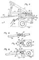
- Fig. 1 is a plan view of an embodiment of an agricultural machine according the invention attached to a tractor.
- Fig. 2 is an enlarged view of part of Fig. 1.
- Fig. 3 is a side elevation of the machine shown in Fig. 1.
- Fig. 4 is a partly sectional elevational view taken on the lines IV-IV in Fig. 2.
- Fig. 5 is a partly sectional elevational view taken on the lines V-V in Fig. 2.
- Fig. 6 is a partly sectional elevational view taken on the lines VI-VI in Fig. 2.
- Fig. 7 is a plan view of the machine of the preceding Figures in a transport position.
- Fig. 1 shows a plan view of a rotary haymaking machine hitched to a tractor in a first embodiment of the agricultural implement in accordance with the invention, whilst the parts most important for the invention are shown in Fig. 2 on an enlarged scale. Apart from the screening members and their mode of fastening in accordance with the invention, the further part of the rotary haymaking machine is shown in a general view.
- the rotary haymaking machine 1 comprises a main frame beam 2, which is substantially horizontal and extends transversely of the direction of travel A.
- the main frame beam 2 is rigidly secured by means of supports 3 to a trestle 4 in the form of an inverted U provided near the top and near the two lower ends with connecting means 5, to each of which can be fastened one of the arms 6 of the three-point lifting device of a tractor 7.
- a tractor 7 Of the tractor 7 only the rear part of the tractor is shown, comprising a cab 8 and mudguards 9 covering ground wheels of the tractor on the top and rear sides.
- each of the rake members 10 comprises in this embodiment a plurality of spokes 12, to the ends of which are secured groups of tines 13, the tines being first downwardly inclined away from the ends of the associated spokes 12 and being then outwardly bent over so as to be directed substantially parallel to a plane at right angles to the rotary shaft 11 concerned. Therefore, viewed in the direction of the associated rotary shaft 11 the tine ends are located at a distance below the free end of a spoke 12.
- each end of the main frame beam 2 is provided a bearing for a pivotal shaft 14, which is directed substantially horizontally and parallel to the direction of travel A.
- a frame beam 15 is journalled
- a rake member 10 which can be driven by means of the tractor about a rotary shaft 16 extending parallel to the rotary shaft 11 during operation.
- the structures of the two outermost rake members 10 are identical to those of the two inner rake members 10 and may, therefore, be provided with tines or groups of tines extending outwardly or with groups of tines directed fully downwards, in which case the tine ends are located at a distance below the spokes 12.
- the rotary hay-making machine 1 may be provided with pairs of swath boards which can be set both in an operative position and an inoperative position with respect to the rest of the machine.
- Each of the four rake members 10 is supported in known manner by a ground wheel, which may in this case be freely pivotable about the associated rotary shaft 11 or 16 respectively.
- the two frame beams 15 together with the outermost rake members 10 fastened to them can freely turn up and down about the associated pivotal shaft 14 in order to permit the outermost rake members 10 to match unevenness of the ground.
- a second function known per se of the pivotal shafts 14 lies in that for transport purposes the two outer frame beams 15 with the outermost rake members 10 fastened to them can be tilted up in a manner such that the frame beams 15 extend upwardly. This latter possibility provides a smaller width of the machine during transport.
- a hydraulic ram 17 connected with the hydraulic system of the tractor 7 and controllable from the cab 8.
- the hydraulic ram 17 is a single-action ram; after hydraulic energization of the ram its piston rod slides inwardly into the cylinder space.
- the end of the cylinder itself is fastened to the frame beam by means of an upwardly directed support 18 rigidly secured to one of the frame beams 15, whereas the end of the piston rod is pivotally connected in a similar manner with the frame beam by means of an upwardly directed support 19 rigidly secured to the other frame beam 15.
- the two frame beams 15 are turned upwards towards one another into a position in which further turning of the frame beams 15 with respect to the main frame beam 2 is prevented by a stop or stops.
- the main frame beam is provided with two resilient stops so that in the transport position the two frame beams 15 are in resilient contact with the stops so that, when the hydraulic pressure in the ram 17 is obviated, the resilient stops impart to the two frame beams 15 an outward impulse after which the frame beams 15 with the rake members fastened thereto turn downwards into the working position, whilst the hydraulic fluid flowing out of the cylinder is conducted away in a controller manner through a relatively light-structured relief valve.
- the invention proposes inter alia a simple replacement of these resilient stops, as will be explained more fully hereinbelow.
- Each of the frame beams 15 is provided with a locking pin 20, which is horizontal and directed forwardly, whilst near each locking pin 20 at the end of the main frame beam 2 a lock bolt 21 is provided, which automatically falls around the neighbouring pin 20 during the upward turn of the frame beam 15 so that during transport the frame beams 15 are fixed in place.
- each of the lock bolts 21 is fastened a rope extending into the cab 8.
- the hydraulic ram 17 is briefly energized so that the driver can lift the lock bolts by pulling the ropes, after which the frame beams 15 are released to move downwards.
- Each of the outer parts of the haymaking machine 1, said parts having each a frame beam 15 and an outermost rake member 10, is provided with a screening member 22, which is substantially horizontal and is located, viewed with respect to the direction of travel, at least in this embodiment, in front of the outermost rake member 10.
- the bracket-shaped screening member 22 embraces the sides and, in addition, the front of the foremost half of the rake member 10 concerned in conformity to prevailing provisions. This protection is intended to prevent persons standing at the front or a side of the rake member from coming into contact with the driven tines and from thus being injured.
- Each of the frame beams 15 is provided at relatively spaced places with supporting plates 23 and 24 respectively, which are directed upwards and in the direction of travel A in the working position of the machine and which protrude in front of the frame beam 15.
- To the front of each of these plates is rigidly but releasbly secured a plate-shaped support 25 and 26 respectively, these supports 25 and 26 projecting to the front away from the plates 23 and 24.
- the supports 25 and 26 are, therefore, also rigidly secured with respect to the frame beam 15.
- Each of the supports 25 and 26 has on the rear side a cavity to receive a tubular shaft 27, the centre line 28 of which is parallel to that of the frame beam 15 and thus extends substantially horizontally and transversely of the direction of travel A during operation. From Fig.
- bracket 22 embracing the front part of the frame member 10.
- the bracket 22 together with the shaft 27 can turn in the space bounded by the parts 23, 25 and 24, 26 respectively, in which space the shaft 27 is journalled as a pivotal shaft.
- the shaft 27 is provided with a plate 29, which is parallel to the plate-shaped support 25, but, in contrast to the plate 25, is rigidly secured to the shaft 27.
- the plate 29 is located on the side of the support 25 away from the support 26 (at a short distance from said support) and projects forwardly beyond the shaft 27, as will be seen in Fig. 6.
- a pin 30 perpendicular to the plate 25 and projecting for a given distance in the direction of the plate 29.
- a recess 31 through which passes a torsion bar 32 substantially parallel to the centre line 28.
- This torsion bar 32 extends, viewed in the outward direction, (Fig. 2) beyond the plate 26 up to a plate-shaped clamp 33 which is rigidly secured to the shaft 27.
- the torsion bar 32 is bent back through 180° at the area of the clamp 33 and the bent-back end is located in the clamp 33, which is rigidly secured to the shaft 27.
- the other end of the torsion bar 32 extends through the recess 31 in the supporting plate 25 and is bent over in forward direction through 90° directly on the inner side of the plate 25 to form a rod portion 34.
- the rod portion 34 formed by the end of the torsion bar 32 is in contact with the pin 30 rigidly secured to the plate 25 near its free end (at a distance from the recess 31 in the plate 25) (Fig. 6).
- a horizontal rod 35 extending transversely of the direction of travel and having at both ends stops formed by the two limbs 36 and 37 of an abutment pipe 38 bent through about 90°.
- the limb 36 of the pipe 38 is disposed, viewed in a direction transverse of the direction of travel A, at a short distance inside the inner boundary of the bracket 22 and is directed substantially vertically.
- the other limb 37 viewed in the direction towards its free end, is outwardly and rearwardly inclined and, as will be seen from Fig. 2, it is located below the inner part of the bracket 22.
- bracket 22 having a bias tension during the operation of the machine is located at a relatively small distance above the limb 37 of the abutment pipe 38.
- the bracket 22 can turn downwards against the effect of the torsion bar 32 until the inner boundary of the bracket 22 strikes the limb 37.
- the precaution is taken with a view to persons coming into contact with the bracket 22: if the bracket 22 could turn freely downwards, said person would be in direct risk of contacting the rotating rake member 10.
- the stop 37 prevents this free downward turn and continues protecting.
- each bracket 22 comes into contact with the upwardly extending limb 36 of the stop 38.
- the bracket 22 is turned downwards with respect to the frame beam 15 (or rather outwards, if it is already in the upwardly turned position) into the final position shown in Fig. 7, in which the torsion bar 32 is fully or almost fully stressed.
- the force exerted by the torsion bar 32 is, in the position shown in Fig. 7, in equilibrium with the force exerted by the ram 17. In this final position the piston and the piston rod of the ram find themselves a stop with respect to the cylinder wall. From Fig.
- reference numeral 22' designates the position, indicated by broken lines, in which the bracket 22 would be located, if the position of this bracket with respect to the frame beam 15 were maintained in the working state. In this case the bracket would have come into contact with tractor parts, in this case the mudguards 9.
- the machine can be attached at a smaller distance from the tractor or the lifting device 6 so that the position of the centre of gravity of the machine is improved with respect to the tractor.
- a third advantage of the construction embodying the invention resides in that, as stated above, in the transport position of the haymaking machine the bracket 22 engages with spring tension the upright limb 36 of the abutment pipe 38 so that the reactive force is an outwardly directed force exerted on the frame beam 15, which is substantially vertical in the transport position.
- the tractor driver has lifted the lock bolts 21 by means of the ropes, the frame beams 15 with the outermost rake members 10 fastened thereto are urged outwardly by the spring tension produced by the brackets 22, after which the frame beams 15 and the outermost rake members can lower further into the working position by their own weight.
- the above-mentioned resilient stops can be dispensed with, since their function is taken over by the bracket 22.
Landscapes
- Life Sciences & Earth Sciences (AREA)
- Environmental Sciences (AREA)
- Agricultural Machines (AREA)
Description
- The invention relates to an agricultural implement comprising a frame connectable to a tractor and constituted by an inner main frame beam and further outer frame beams pivotable with respect to said main frame beam about pivot shafts substantially in the direction (A) of operative travel, which main frame beam and further frame beams extend in a first, operative position in a substantially horizontal direction transverse to the direction (A) of operative travel, the implement further comprising tractor drivable inner and outer rake members, each of the rake members comprising a plurality of spokes to the ends of which are secured groups of tines, the inner rake members being coupled to said main frame beam, the outer rake members being coupled to said further frame beams, and with said further frame beams pivotable upwardly around said pivot shafts in a second transport position, the inner and outer rake members in the first position being rotatable about upwardly directed rotary shafts, the implement still further comprising for each outer frame beam at each side of the main frame beam a protective member which, with respect to the direction (A) of operative travel, protects in said first position of said rake members e.g. persons from contact with at least a foremost part of a rake member, connecting means are provided between each protective member and its corresponding outer rake member to permit that said protective members be moved into another position by moving the outer rake members into the second position.
- An agricultural implement of this kind is known from DE-A-14 82 104 (Fig. 5) which describes a haymaking machine with upwards movable rake members and a protective member constituted by protective elements partially around the outermost rake members and in a fixed position relative to these outer rake members and by chains or rope-like elements connecting the protective elements before and behind the row of rake members. In the transport position the protective member has completely lost its protective function.
- The invention has for its object to provide the performance of a further task of the protective member in order to utilize it more effectively, particularly in the transport position of the implement.
- According to the invention, the implement is characterized in that each of the protective members (22) is rigid and embraces at least the foremost half of a respective rake member and that adjusting means, different from the connecting means, are provided, which limit the movement of the protective members caused by the outer rake members such that the movement of the protective members is modified with respect to the movement which these would have if no adjusting means were provided, and such that the position of the protective members relative to the respective outer rake members is automatically changed by moving the outer rake members hydraulically into the second position, the other position of the protective members being forward and at least partially laterally outboard of the respective outer rake membes, whereby protection of e.g. persons from contact with at least a foremost part of the outer rake member is maintained.
- For a better understanding of the invention and to show how the same may be carried into effect reference will be made by way of example to the accompanying drawing.
- Fig. 1 is a plan view of an embodiment of an agricultural machine according the invention attached to a tractor.
- Fig. 2 is an enlarged view of part of Fig. 1.
- Fig. 3 is a side elevation of the machine shown in Fig. 1.
- Fig. 4 is a partly sectional elevational view taken on the lines IV-IV in Fig. 2.
- Fig. 5 is a partly sectional elevational view taken on the lines V-V in Fig. 2.
- Fig. 6 is a partly sectional elevational view taken on the lines VI-VI in Fig. 2.
- Fig. 7 is a plan view of the machine of the preceding Figures in a transport position.
- Fig. 1 shows a plan view of a rotary haymaking machine hitched to a tractor in a first embodiment of the agricultural implement in accordance with the invention, whilst the parts most important for the invention are shown in Fig. 2 on an enlarged scale. Apart from the screening members and their mode of fastening in accordance with the invention, the further part of the rotary haymaking machine is shown in a general view.
- The
rotary haymaking machine 1 comprises amain frame beam 2, which is substantially horizontal and extends transversely of the direction of travel A. Themain frame beam 2 is rigidly secured by means ofsupports 3 to a trestle 4 in the form of an inverted U provided near the top and near the two lower ends with connectingmeans 5, to each of which can be fastened one of thearms 6 of the three-point lifting device of atractor 7. Of thetractor 7 only the rear part of the tractor is shown, comprising a cab 8 and mudguards 9 covering ground wheels of the tractor on the top and rear sides. - Near the two ends of the
main frame beam 2rake members 10 are journalled so as to be drivable in known manner from thetractor 7 about upwardly directedrotary shafts 11. Each of therake members 10 comprises in this embodiment a plurality ofspokes 12, to the ends of which are secured groups oftines 13, the tines being first downwardly inclined away from the ends of the associatedspokes 12 and being then outwardly bent over so as to be directed substantially parallel to a plane at right angles to therotary shaft 11 concerned. Therefore, viewed in the direction of the associatedrotary shaft 11 the tine ends are located at a distance below the free end of aspoke 12. To the ends of thespokes 12 of the rake members may, of course, also be secured tines which extend downwards or which are outwardly and downwardly inclined in the operative position. Near each end of themain frame beam 2 is provided a bearing for apivotal shaft 14, which is directed substantially horizontally and parallel to the direction of travel A. About each of thepivotal shafts 14 is pivotable aframe beam 15, which, in operation, is substantially in line with theframe beam 2. Near the outermost end of eachframe beam 15 is journalled arake member 10, which can be driven by means of the tractor about arotary shaft 16 extending parallel to therotary shaft 11 during operation. The structures of the twooutermost rake members 10 are identical to those of the twoinner rake members 10 and may, therefore, be provided with tines or groups of tines extending outwardly or with groups of tines directed fully downwards, in which case the tine ends are located at a distance below thespokes 12. - The rotary hay-making
machine 1 may be provided with pairs of swath boards which can be set both in an operative position and an inoperative position with respect to the rest of the machine. - Each of the four
rake members 10 is supported in known manner by a ground wheel, which may in this case be freely pivotable about the associatedrotary shaft - During operation the two
frame beams 15 together with theoutermost rake members 10 fastened to them can freely turn up and down about the associatedpivotal shaft 14 in order to permit theoutermost rake members 10 to match unevenness of the ground. - A second function known per se of the
pivotal shafts 14 lies in that for transport purposes the twoouter frame beams 15 with theoutermost rake members 10 fastened to them can be tilted up in a manner such that theframe beams 15 extend upwardly. This latter possibility provides a smaller width of the machine during transport. - In the rotary haymaking machine shown in Fig. 1 tilting up the two
frame beams 15 with theoutermost rake members 10 fastened thereto is performed by ahydraulic ram 17 connected with the hydraulic system of thetractor 7 and controllable from the cab 8. Thehydraulic ram 17 is a single-action ram; after hydraulic energization of the ram its piston rod slides inwardly into the cylinder space. The end of the cylinder itself is fastened to the frame beam by means of an upwardly directedsupport 18 rigidly secured to one of theframe beams 15, whereas the end of the piston rod is pivotally connected in a similar manner with the frame beam by means of an upwardly directedsupport 19 rigidly secured to theother frame beam 15. - After energization of the
hydraulic ram 17 the twoframe beams 15 are turned upwards towards one another into a position in which further turning of theframe beams 15 with respect to themain frame beam 2 is prevented by a stop or stops. In a known embodiment the main frame beam is provided with two resilient stops so that in the transport position the twoframe beams 15 are in resilient contact with the stops so that, when the hydraulic pressure in theram 17 is obviated, the resilient stops impart to the twoframe beams 15 an outward impulse after which the frame beams 15 with the rake members fastened thereto turn downwards into the working position, whilst the hydraulic fluid flowing out of the cylinder is conducted away in a controller manner through a relatively light-structured relief valve. The invention proposes inter alia a simple replacement of these resilient stops, as will be explained more fully hereinbelow. - Each of the
frame beams 15 is provided with alocking pin 20, which is horizontal and directed forwardly, whilst near eachlocking pin 20 at the end of the main frame beam 2 alock bolt 21 is provided, which automatically falls around the neighbouringpin 20 during the upward turn of theframe beam 15 so that during transport theframe beams 15 are fixed in place. - To each of the
lock bolts 21 is fastened a rope extending into the cab 8. When the driver wants to turn theframe beams 15 out of the transport position into the working position, thehydraulic ram 17 is briefly energized so that the driver can lift the lock bolts by pulling the ropes, after which theframe beams 15 are released to move downwards. Each of the outer parts of thehaymaking machine 1, said parts having each aframe beam 15 and anoutermost rake member 10, is provided with ascreening member 22, which is substantially horizontal and is located, viewed with respect to the direction of travel, at least in this embodiment, in front of theoutermost rake member 10. The bracket-shaped screening member 22 embraces the sides and, in addition, the front of the foremost half of therake member 10 concerned in conformity to prevailing provisions. This protection is intended to prevent persons standing at the front or a side of the rake member from coming into contact with the driven tines and from thus being injured. - The mode of fastening of the
bracket 22 is illustrated in Figs. 2 to 6. - Each of the
frame beams 15 is provided at relatively spaced places with supportingplates frame beam 15. To the front of each of these plates is rigidly but releasbly secured a plate-shaped support plates supports frame beam 15. Each of thesupports tubular shaft 27, thecentre line 28 of which is parallel to that of theframe beam 15 and thus extends substantially horizontally and transversely of the direction of travel A during operation. From Fig. 2 it is apparent that to the two ends of theshaft 27 is rigidly secured thebracket 22 embracing the front part of theframe member 10. Thebracket 22 together with theshaft 27 can turn in the space bounded by theparts shaft 27 is journalled as a pivotal shaft. - Referring to Figs. 2 and 6, the
shaft 27 is provided with aplate 29, which is parallel to the plate-shaped support 25, but, in contrast to theplate 25, is rigidly secured to theshaft 27. Theplate 29 is located on the side of thesupport 25 away from the support 26 (at a short distance from said support) and projects forwardly beyond theshaft 27, as will be seen in Fig. 6. - To the
plate 25 is rigidly secured apin 30 perpendicular to theplate 25 and projecting for a given distance in the direction of theplate 29. - In the
support 25 as well as in thesupport 26 is provided arecess 31, through which passes atorsion bar 32 substantially parallel to thecentre line 28. Thistorsion bar 32 extends, viewed in the outward direction, (Fig. 2) beyond theplate 26 up to a plate-shaped clamp 33 which is rigidly secured to theshaft 27. Thetorsion bar 32 is bent back through 180° at the area of theclamp 33 and the bent-back end is located in theclamp 33, which is rigidly secured to theshaft 27. The other end of thetorsion bar 32 extends through therecess 31 in the supportingplate 25 and is bent over in forward direction through 90° directly on the inner side of theplate 25 to form arod portion 34. Therod portion 34 formed by the end of thetorsion bar 32 is in contact with thepin 30 rigidly secured to theplate 25 near its free end (at a distance from therecess 31 in the plate 25) (Fig. 6). - From Figs. 4 and 6 it is apparent that the
rod portion 34 is upwardly inclined away from therecess 31, whereas the end near theclamp 33 is directed substantially horizontally or slightly downwardly. This means that thetorsion bar 32 is prestressed. Since therod portion 34 is supported with respect to theframe beam 15 via thepin 30, thesupport 25 and the supportingplate 23, thestressed torsion bar 32 tends to exert via the clamp 33 a torsional moment on the outermost end of theshaft 27 and thebracket 22 in upward direction. However, this is prevented since upon an upward turn of thebracket 22 and theshaft 27 theplate 29 rigidly secured to theshaft 27 will come into contact with thepin 30. Therefore, thebracket 22 and theshaft 27 being integral herewith have an internal bias tension which prevents the basicallypivotable bracket 22 from rattling in a troublesome manner in the working position shown in Figs. 2 to 6. - To the supports 3 (Fig. 1) is secured a
horizontal rod 35 extending transversely of the direction of travel and having at both ends stops formed by the twolimbs abutment pipe 38 bent through about 90°. Thelimb 36 of thepipe 38 is disposed, viewed in a direction transverse of the direction of travel A, at a short distance inside the inner boundary of thebracket 22 and is directed substantially vertically. Theother limb 37, viewed in the direction towards its free end, is outwardly and rearwardly inclined and, as will be seen from Fig. 2, it is located below the inner part of thebracket 22. In this situation the above-mentionedbracket 22 having a bias tension during the operation of the machine is located at a relatively small distance above thelimb 37 of theabutment pipe 38. Thebracket 22 can turn downwards against the effect of thetorsion bar 32 until the inner boundary of thebracket 22 strikes thelimb 37. The precaution is taken with a view to persons coming into contact with the bracket 22: if thebracket 22 could turn freely downwards, said person would be in direct risk of contacting therotating rake member 10. Thestop 37 prevents this free downward turn and continues protecting. When thehydraulic ram 17 is actuated, the twoframe beams 15 with therake members 10 journalled thereon turn upwards, as stated above, in order to obtain a transport position in which the machine has a small width. During this upward turn the inner part of eachbracket 22 comes into contact with the upwardly extendinglimb 36 of thestop 38. Upon a further turn of theframe beam 15 thebracket 22 is turned downwards with respect to the frame beam 15 (or rather outwards, if it is already in the upwardly turned position) into the final position shown in Fig. 7, in which thetorsion bar 32 is fully or almost fully stressed. The force exerted by thetorsion bar 32 is, in the position shown in Fig. 7, in equilibrium with the force exerted by theram 17. In this final position the piston and the piston rod of the ram find themselves a stop with respect to the cylinder wall. From Fig. 7 it is apparent that the foremost part of thebracket 22 is located in a plane located beyond the plane of the tine ends of theoutermost rake members 10, viewed with respect to the vertical plane of symmetry of the rotary haymaking machine. The plane going through the outermost ends of the tines of these outermost rake members is designated in Fig. 7 byreference numeral 39. It is thus ensured that persons located at the side of the travelling combination of tractor and haymaking machine are protected from contact with the tine ends of the outermost rape members. - Therefore, also in this second position the screening member is effective.
- The displaced position of the
bracket 22 shown in Fig. 7 results also in the advantage that, when the frame beams 15 are turned up, the bracket does not come into contact with tractor parts. - Referring to Fig. 7, reference numeral 22' designates the position, indicated by broken lines, in which the
bracket 22 would be located, if the position of this bracket with respect to theframe beam 15 were maintained in the working state. In this case the bracket would have come into contact with tractor parts, in this case the mudguards 9. This involves that in accordance with the idea of the invention the machine can be attached at a smaller distance from the tractor or thelifting device 6 so that the position of the centre of gravity of the machine is improved with respect to the tractor. - A third advantage of the construction embodying the invention resides in that, as stated above, in the transport position of the haymaking machine the
bracket 22 engages with spring tension theupright limb 36 of theabutment pipe 38 so that the reactive force is an outwardly directed force exerted on theframe beam 15, which is substantially vertical in the transport position. After, as described above, the tractor driver has lifted thelock bolts 21 by means of the ropes, the frame beams 15 with theoutermost rake members 10 fastened thereto are urged outwardly by the spring tension produced by thebrackets 22, after which the frame beams 15 and the outermost rake members can lower further into the working position by their own weight. As a result, the above-mentioned resilient stops can be dispensed with, since their function is taken over by thebracket 22.
Claims (3)
- An agricultural implement comprising a frame (2, 15) connectable to a tractor and constituted by an inner main frame beam (2) and further outer frame beams (15) pivotable with respect to said main frame beam (2) about pivot shafts (14) substantially in the direction (A) of operative travel, which main frame beam (2) and further frame beams (15) extend in a first, operative position in a substantially horizontal direction transverse to the direction (A) of operative travel, the implement further comprising tractor drivable inner and outer rake members (10), each of the rake members (10) comprising a plurality of spokes (12) to the ends of which are secured groups of tines (13), the inner rake members being coupled to said main frame beam (2), the outer rake members being coupled to said further frame beams (15), and with said further frame beams (15) pivotable upwardly around said pivot shafts (14 ) in a second, transport position, the inner and outer rake members (10) in the first position being rotatable about upwardly directed rotary shafts (11), the implement still further comprising for each outer frame beam (15) at each side of the main frame beam (15) a protective member (22) which, with respect to the direction (A) of operative travel, protects in said first position of said rake members e.g. persons from contact with at least a foremost part of a rake member, connecting means (23, 24, 25, 26, 32, 30, 29) are provided between each protective member (22) and its corresponding outer rake member (10) to permit that said protective members (22) be moved into another position by moving the outer rake members into the second position, characterized in that each of the protective members (22) is rigid and embraces at least the foremost half of a respective rake member and that adjusting means (36, 37), different from the connecting means are provided, which limit the movement of the protective members caused by the outer rake members, such that the movement of the protective members is modified with respect to the movement which these would have if no adjusting means were provided, and such that the position of the protective members (22) relative to the respective outer rake members is automatically changed by moving the outer rake members hydraulically into the second position, the other position of the protective members (22) being forward and at least partially laterally outboard of the respective outer rake members, whereby protection of e.g. persons from contact with at least a foremost part of the outer rake member is maintained.
- An agricultural implement as claimed in claim 1, characterized in that, when the outer rake members are pivoted from the first into the second position, the adjusting means (36, 37) urges each of the protective members (22) into the other position against resilient force (32).
- An agricultural implement as claimed in claim 2, characterized in that the adjusting means (36, 37) comprises stop means (38) connected to the main frame beam (2) and engaging each of the protective members (22) during at least a part of their upward movement.
Applications Claiming Priority (2)
| Application Number | Priority Date | Filing Date | Title |
|---|---|---|---|
| NL8105770A NL188013B (en) | 1981-12-22 | 1981-12-22 | AGRICULTURAL IMPLEMENT. |
| NL8105770 | 1981-12-22 |
Publications (3)
| Publication Number | Publication Date |
|---|---|
| EP0083460A1 EP0083460A1 (en) | 1983-07-13 |
| EP0083460B1 EP0083460B1 (en) | 1989-01-25 |
| EP0083460B2 true EP0083460B2 (en) | 1995-05-10 |
Family
ID=19838589
Family Applications (1)
| Application Number | Title | Priority Date | Filing Date |
|---|---|---|---|
| EP19820201644 Expired - Lifetime EP0083460B2 (en) | 1981-12-22 | 1982-12-21 | Agricultural implement |
Country Status (3)
| Country | Link |
|---|---|
| EP (1) | EP0083460B2 (en) |
| DE (1) | DE3279383D1 (en) |
| NL (1) | NL188013B (en) |
Families Citing this family (13)
| Publication number | Priority date | Publication date | Assignee | Title |
|---|---|---|---|---|
| DE3645021A1 (en) * | 1986-09-26 | 1988-08-11 | Wide swath hay gathering machine | |
| EP0427357B1 (en) * | 1986-12-23 | 1995-10-18 | C. van der Lely N.V. | An agricultural machine |
| NL8800065A (en) * | 1987-06-23 | 1989-01-16 | Lely Nv C Van Der | HAY CONSTRUCTION MACHINE. |
| FR2621213B1 (en) * | 1987-10-01 | 1990-01-05 | Kuhn Sa | FENAISON MACHINE WITH AN IMPROVED PROTECTION DEVICE |
| DE3739114C2 (en) * | 1987-11-19 | 1999-04-08 | Claas Saulgau Gmbh | Protection device for rotary hay machines |
| EP0316559B2 (en) * | 1987-11-19 | 1998-12-02 | Claas Saulgau Gmbh | Protective device for rotary tedder |
| DE3743025C2 (en) * | 1987-12-18 | 1998-03-26 | Claas Saulgau Gmbh | Protection bar for rotary hay machines |
| NL9100572A (en) * | 1991-04-03 | 1992-11-02 | Lely Nv C Van Der | AGRICULTURAL MACHINE. |
| FR2687891B1 (en) * | 1992-02-28 | 1994-05-20 | Kuhn Sa | MOWER WITH AN IMPROVED PROTECTIVE MEMBER. |
| FR2687892B1 (en) * | 1992-02-28 | 1994-05-20 | Kuhn Sa | FORAGE RAKER WITH A MECHANISM TO INTERRUPT ROTOR DRIVE. |
| FR2726152B1 (en) * | 1994-10-28 | 1997-01-24 | Kuhn Sa | AGRICULTURAL MACHINE FOR CUTTING PLANTS WITH IMPROVED PROTECTION DEVICE |
| DE19541654A1 (en) * | 1995-11-08 | 1997-05-15 | Claas Saulgau Gmbh | Arrangement of protective bars for multi-rotor tedders |
| FR2746577B1 (en) * | 1996-03-29 | 1998-05-29 | Kuhn Sa | FENAISON MACHINE HAVING A MOVABLE PROTECTION DEVICE |
Family Cites Families (8)
| Publication number | Priority date | Publication date | Assignee | Title |
|---|---|---|---|---|
| DE1482104A1 (en) * | 1962-05-07 | 1969-01-30 | Fahr Ag Maschf | Haymaking machine with several tine notches that are arranged side by side and run almost horizontally |
| DE1582369A1 (en) * | 1967-12-02 | 1970-10-15 | Friedrich Moertl | Protection device for mowing machines with rotating cutting units, which are driven from below |
| FR2063497A5 (en) * | 1969-10-14 | 1971-07-09 | Kuhn Freres & Cie | |
| DE2127739B1 (en) * | 1971-06-04 | 1972-07-13 | Wilhelm Stoll Maschinenfabrik Gmbh, 3325 Broistedt | Haymaking machine |
| NL7204572A (en) * | 1972-04-06 | 1973-10-09 | ||
| NL170221C (en) * | 1973-05-15 | 1985-10-16 | Lely Nv C Van Der | HAY CONSTRUCTION MACHINE. |
| NL7607093A (en) * | 1976-06-29 | 1978-01-02 | Texas Industries Inc | MACHINE FOR CROP PROCESSING. |
| NL7710410A (en) * | 1977-09-23 | 1979-03-27 | Patent Concern Nv | MACHINE FOR TILLING GROUND, MOWED CROP. |
-
1981
- 1981-12-22 NL NL8105770A patent/NL188013B/en not_active Application Discontinuation
-
1982
- 1982-12-21 DE DE8282201644T patent/DE3279383D1/en not_active Expired
- 1982-12-21 EP EP19820201644 patent/EP0083460B2/en not_active Expired - Lifetime
Also Published As
| Publication number | Publication date |
|---|---|
| EP0083460B1 (en) | 1989-01-25 |
| NL188013B (en) | 1991-10-16 |
| EP0083460A1 (en) | 1983-07-13 |
| NL8105770A (en) | 1983-07-18 |
| DE3279383D1 (en) | 1989-03-02 |
Similar Documents
| Publication | Publication Date | Title |
|---|---|---|
| EP0083460B2 (en) | Agricultural implement | |
| CA1236698A (en) | Latch assembly for holding a front mounted implement in a raised position | |
| CA2278073A1 (en) | Suspension system for a work vehicle | |
| US4330981A (en) | Towable ganged mower | |
| US3883965A (en) | Snow plow frame | |
| EP0012780B1 (en) | Tractor front implement hitch | |
| US4664404A (en) | Tractor rear weight and hitch assembly | |
| CA2055767C (en) | Field cultivator leveling device | |
| US3832835A (en) | Seven gang hydraulic reel mower | |
| US5833011A (en) | Landscaping rake-leveling device | |
| US3949889A (en) | Front end loader | |
| CA2277518C (en) | Windrower platform side-to-side float balance adjustment | |
| CA2119294C (en) | Harrow | |
| AU2401799A (en) | Suspension for a mowing unit | |
| US3925971A (en) | Gauging apparatus for implement head | |
| CA1217640A (en) | Ditch swather | |
| US6035941A (en) | Tractor with a front loader | |
| SU1595323A3 (en) | Mower | |
| CA1087440A (en) | Plow mounting bracket | |
| US3228484A (en) | Semimounted plow | |
| US4483131A (en) | Tractor-mounted harvester | |
| US2218579A (en) | Sweep rake | |
| GB1573642A (en) | Seatedoperator type tractor | |
| EP0903067A2 (en) | A foldable implement for working crop lying on the soil | |
| US4252198A (en) | Ground levelling attachment for tractors |
Legal Events
| Date | Code | Title | Description |
|---|---|---|---|
| PUAI | Public reference made under article 153(3) epc to a published international application that has entered the european phase |
Free format text: ORIGINAL CODE: 0009012 |
|
| AK | Designated contracting states |
Designated state(s): DE FR GB |
|
| 17P | Request for examination filed |
Effective date: 19831230 |
|
| GRAA | (expected) grant |
Free format text: ORIGINAL CODE: 0009210 |
|
| AK | Designated contracting states |
Kind code of ref document: B1 Designated state(s): DE FR GB |
|
| REF | Corresponds to: |
Ref document number: 3279383 Country of ref document: DE Date of ref document: 19890302 |
|
| ET | Fr: translation filed | ||
| PLBI | Opposition filed |
Free format text: ORIGINAL CODE: 0009260 |
|
| PLBI | Opposition filed |
Free format text: ORIGINAL CODE: 0009260 |
|
| 26 | Opposition filed |
Opponent name: CLAAS SAALGAU GMBH Effective date: 19890930 |
|
| 26 | Opposition filed |
Opponent name: MASCHINENFABRIKEN BERNHARD KRONE GMBH Effective date: 19891024 Opponent name: FELLA-WERKE GMBH Effective date: 19891024 Opponent name: KUHN S.A. Effective date: 19891020 Opponent name: CLAAS SAALGAU GMBH Effective date: 19890930 |
|
| PLAB | Opposition data, opponent's data or that of the opponent's representative modified |
Free format text: ORIGINAL CODE: 0009299OPPO |
|
| R26 | Opposition filed (corrected) |
Opponent name: CLAAS SAALGAU GMBH * 891020 KUHN S.A. * 891024 FEL Effective date: 19890930 |
|
| PUAH | Patent maintained in amended form |
Free format text: ORIGINAL CODE: 0009272 |
|
| STAA | Information on the status of an ep patent application or granted ep patent |
Free format text: STATUS: PATENT MAINTAINED AS AMENDED |
|
| 27A | Patent maintained in amended form |
Effective date: 19950510 |
|
| AK | Designated contracting states |
Kind code of ref document: B2 Designated state(s): DE FR GB |
|
| ET3 | Fr: translation filed ** decision concerning opposition | ||
| PGFP | Annual fee paid to national office [announced via postgrant information from national office to epo] |
Ref country code: FR Payment date: 20011130 Year of fee payment: 20 |
|
| PGFP | Annual fee paid to national office [announced via postgrant information from national office to epo] |
Ref country code: GB Payment date: 20011204 Year of fee payment: 20 Ref country code: DE Payment date: 20011204 Year of fee payment: 20 |
|
| REG | Reference to a national code |
Ref country code: GB Ref legal event code: IF02 |
|
| PG25 | Lapsed in a contracting state [announced via postgrant information from national office to epo] |
Ref country code: GB Free format text: LAPSE BECAUSE OF EXPIRATION OF PROTECTION Effective date: 20021220 |
|
| REG | Reference to a national code |
Ref country code: GB Ref legal event code: PE20 Effective date: 20021220 |
|
| APAH | Appeal reference modified |
Free format text: ORIGINAL CODE: EPIDOSCREFNO |
|
| PLAB | Opposition data, opponent's data or that of the opponent's representative modified |
Free format text: ORIGINAL CODE: 0009299OPPO |