EP0083391A2 - Tyre for vehicles - Google Patents
Tyre for vehicles Download PDFInfo
- Publication number
- EP0083391A2 EP0083391A2 EP82108530A EP82108530A EP0083391A2 EP 0083391 A2 EP0083391 A2 EP 0083391A2 EP 82108530 A EP82108530 A EP 82108530A EP 82108530 A EP82108530 A EP 82108530A EP 0083391 A2 EP0083391 A2 EP 0083391A2
- Authority
- EP
- European Patent Office
- Prior art keywords
- tire
- flanks
- rim
- tread
- rim flange
- Prior art date
- Legal status (The legal status is an assumption and is not a legal conclusion. Google has not performed a legal analysis and makes no representation as to the accuracy of the status listed.)
- Withdrawn
Links
Images


Classifications
-
- B—PERFORMING OPERATIONS; TRANSPORTING
- B60—VEHICLES IN GENERAL
- B60C—VEHICLE TYRES; TYRE INFLATION; TYRE CHANGING; CONNECTING VALVES TO INFLATABLE ELASTIC BODIES IN GENERAL; DEVICES OR ARRANGEMENTS RELATED TO TYRES
- B60C17/00—Tyres characterised by means enabling restricted operation in damaged or deflated condition; Accessories therefor
- B60C17/04—Tyres characterised by means enabling restricted operation in damaged or deflated condition; Accessories therefor utilising additional non-inflatable supports which become load-supporting in emergency
- B60C17/06—Tyres characterised by means enabling restricted operation in damaged or deflated condition; Accessories therefor utilising additional non-inflatable supports which become load-supporting in emergency resilient
-
- B—PERFORMING OPERATIONS; TRANSPORTING
- B60—VEHICLES IN GENERAL
- B60B—VEHICLE WHEELS; CASTORS; AXLES FOR WHEELS OR CASTORS; INCREASING WHEEL ADHESION
- B60B21/00—Rims
- B60B21/12—Appurtenances, e.g. lining bands
-
- B—PERFORMING OPERATIONS; TRANSPORTING
- B60—VEHICLES IN GENERAL
- B60C—VEHICLE TYRES; TYRE INFLATION; TYRE CHANGING; CONNECTING VALVES TO INFLATABLE ELASTIC BODIES IN GENERAL; DEVICES OR ARRANGEMENTS RELATED TO TYRES
- B60C17/00—Tyres characterised by means enabling restricted operation in damaged or deflated condition; Accessories therefor
- B60C17/009—Tyres characterised by means enabling restricted operation in damaged or deflated condition; Accessories therefor comprising annular protrusions projecting into the tyre cavity
-
- B—PERFORMING OPERATIONS; TRANSPORTING
- B60—VEHICLES IN GENERAL
- B60C—VEHICLE TYRES; TYRE INFLATION; TYRE CHANGING; CONNECTING VALVES TO INFLATABLE ELASTIC BODIES IN GENERAL; DEVICES OR ARRANGEMENTS RELATED TO TYRES
- B60C17/00—Tyres characterised by means enabling restricted operation in damaged or deflated condition; Accessories therefor
- B60C17/04—Tyres characterised by means enabling restricted operation in damaged or deflated condition; Accessories therefor utilising additional non-inflatable supports which become load-supporting in emergency
-
- B—PERFORMING OPERATIONS; TRANSPORTING
- B60—VEHICLES IN GENERAL
- B60C—VEHICLE TYRES; TYRE INFLATION; TYRE CHANGING; CONNECTING VALVES TO INFLATABLE ELASTIC BODIES IN GENERAL; DEVICES OR ARRANGEMENTS RELATED TO TYRES
- B60C3/00—Tyres characterised by the transverse section
-
- Y—GENERAL TAGGING OF NEW TECHNOLOGICAL DEVELOPMENTS; GENERAL TAGGING OF CROSS-SECTIONAL TECHNOLOGIES SPANNING OVER SEVERAL SECTIONS OF THE IPC; TECHNICAL SUBJECTS COVERED BY FORMER USPC CROSS-REFERENCE ART COLLECTIONS [XRACs] AND DIGESTS
- Y10—TECHNICAL SUBJECTS COVERED BY FORMER USPC
- Y10T—TECHNICAL SUBJECTS COVERED BY FORMER US CLASSIFICATION
- Y10T152/00—Resilient tires and wheels
- Y10T152/10—Tires, resilient
- Y10T152/10495—Pneumatic tire or inner tube
- Y10T152/10522—Multiple chamber
- Y10T152/10576—Annular chambers
- Y10T152/10612—Annular chambers with simultaneous inflating means
-
- Y—GENERAL TAGGING OF NEW TECHNOLOGICAL DEVELOPMENTS; GENERAL TAGGING OF CROSS-SECTIONAL TECHNOLOGIES SPANNING OVER SEVERAL SECTIONS OF THE IPC; TECHNICAL SUBJECTS COVERED BY FORMER USPC CROSS-REFERENCE ART COLLECTIONS [XRACs] AND DIGESTS
- Y10—TECHNICAL SUBJECTS COVERED BY FORMER USPC
- Y10T—TECHNICAL SUBJECTS COVERED BY FORMER US CLASSIFICATION
- Y10T152/00—Resilient tires and wheels
- Y10T152/10—Tires, resilient
- Y10T152/10495—Pneumatic tire or inner tube
- Y10T152/10765—Characterized by belt or breaker structure
Landscapes
- Engineering & Computer Science (AREA)
- Mechanical Engineering (AREA)
- Tires In General (AREA)
Abstract
Ein im Normalbetrieb mit Druckluft gefüllter Kraftfahrzeugreifen, der durch sein niedriges Höhen/Breiten-Verhältnis, seine flache Laufflächenwölbung und seine relativ starren und dicken Flanken auch bei Luftverlust die für eine Weiterfahrt erforderliche Stabilität und ausreichende Laufeigenschaften besitzt.A vehicle tire filled with compressed air in normal operation, which, thanks to its low height / width ratio, its flat tread curvature and its relatively rigid and thick flanks, has the stability and sufficient running properties required for onward travel even when there is air loss.
Description
Die Erfindung betrifft einen mit Druckluft gefüllten Reifen für Kraftfahrzeuge, der aufgrund seiner besonderen Formgebung und der relativ starren Reifenflanken auch bei Luftverlust noch ausreichende Laufeigenschaften und Stabilität besitzt.The invention relates to a tire filled with compressed air for motor vehicles which, due to its special shape and the relatively rigid tire flanks, still has sufficient running properties and stability even when there is air loss.
Bei herkömmlichen luftgefüllten Kraftfahrzeugreifen ist das tragende Element die Karkasse. Dies ist im Prinzip ein Hohlkörper in Form eines Torus aus vulkanisiertem Kautschuk, der auf Zug beanspruchbare Verstärkungselemente (Textil- oder Stahlcordfäden) enthält. Der Hohlkörper ist mit Luft unter Überdruck gefüllt, seine Seitenwände stehen unter Zugspannungen. Das Gewicht des Fahrzeugs wirkt dieser Zugspannung entgegen und hebt sie teilweise auf. Wird ein solcher Reifen undicht und verliert seinen Innendruck, dann überwiegt die durch das Fahrzeuggewicht erzeugte Druckspannung. Der Reifen verliert seine Form und wird beim Abrollen in kürzester Zeit zerstört.In conventional air-filled motor vehicle tires, the supporting element is the carcass. In principle, this is a hollow body in the form of a torus made of vulcanized rubber, which contains reinforcing elements (textile or steel cord threads) that can be subjected to tensile stress. The hollow body is filled with air under excess pressure, its side walls are under tensile stress. The weight of the vehicle counteracts this tension and partially cancels it. If such a tire leaks and loses its internal pressure, then the compressive stress generated by the vehicle weight prevails. The tire loses its shape and is quickly destroyed when it rolls off.
Dieser Nachteil wird durch einen Reifen gemäß vorliegender Erfindung überwunden. Der Reifen hat ein niedriges Höhen/Breiten-Verhältnis und die Lauffläche einen solchen Krümmungsradius, daß sie nur flach nach außen gewölbt ist. Die Reifenflanken sind relativ dick und starr ausgebildet und der Felgenkontur angepaßt. Sie sitzen auf der Felge auf und stützen sich außen auf dem Felgenhorn ab.This disadvantage is overcome by a tire according to the present invention. The tire has a low height / width ratio and the tread has such a radius of curvature that it is only flatly curved outwards. The tire flanks are relatively thick and rigid and are adapted to the rim contour. They sit on the rim and are supported on the outside of the rim flange.
Gegenstand der Erfindung ist ein Kraftfahrzeugreifen, dadurch gekennzeichnet, daß sein Höhen/Breiten-Verhältnis 0,3-0,5:1, sein Laufflächenradius das 0,9-1,1- fache der Reifenbreite und die Dicke der Reifenflanken in Höhe des Felgenhorns 12-20 % der Reifenbreite beträgt.The invention relates to a motor vehicle tire, characterized in that its height / width ratio 0.3-0.5: 1, its tread radius 0.9-1.1 times the tire width and the thickness of the tire flanks at the level of the rim flange Is 12-20% of the tire width.
Vorzugsweise beträgt das Höhen/Breiten-Verhältnis 0,35-0,45:1 und besonders bevorzugt 0,4:1. Der Laufflächenradius ist vorzugsweise ebenso groß wie die Reifenbreite. Die Dicke der Reifenflanken beträgt vorzugsweise 14-18 % der Reifenbreite.The height / width ratio is preferably 0.35-0.45: 1 and particularly preferably 0.4: 1. The tread radius is preferably as large as the tire width. The thickness of the tire flanks is preferably 14-18% of the tire width.
Die Reifenflanken sind bevorzugt so gestaltet, daß ihre Innenwand radial verläuft und senkrecht auf dem Felgenring steht, ihre Außenwand dagegen vom Felgenhorn schräg zur Reifenschulter hin verläuft und der Reifen im Bereich des Felgenhorns sein größtes Widerstandsmoment besitzt.The tire flanks are preferably designed so that their inner wall runs radially and is perpendicular to the rim ring, while their outer wall runs obliquely from the rim flange to the tire shoulder and the tire has its greatest section modulus in the region of the rim flange.
Der Reifen wird zweckmäßigerweise auf einer mehrteiligen Felge montiert. Ein fester und starrer Sitz wird zusätzlich durch einen umlaufenden Textilcord- oder Drahtkern im Fuß der Reifenflanken gewährleistet. Über diesem Kern befindet sich in den Reifenschultern außerdem eine umlaufende Nut, die die notwendigen Bewegungen des Reifenoberteils gegenüber den starren Reifenflanken erleichtert.The tire is expediently mounted on a multi-part rim. A firm and rigid seat is additionally guaranteed by a circumferential textile cord or wire core in the foot of the tire flanks. Above this core there is also a circumferential groove in the tire shoulders, which facilitates the necessary movements of the upper part of the tire in relation to the rigid tire flanks.
Die Innenseite des Reifenoberteils verläuft i.a. parallel zum Felgenboden. Durch die Wölbung der Lauffläche nimmt die Dicke des Oberteils von den Schultern zur Mitte hin zu und beträgt im Zenit 40-55, vorzugsweise 45-50 % der gesamten Reifenhöhe. In der Lauffläche befinden sich bis zu vier, vorzugsweise zwei, umlaufende Profilrillen, die ebenso wie die Nut in der Reifenschulter eine Tiefe von 8-12 %, vorzugsweise von 10 % der Reifenhöhe, besitzen. Das Reifenoberteil ist außerdem durch eine umlaufende Einlage aus Stahl- oder Textilcord verstärkt, wodurch auch während des Laufs eine unerwünschte Ausdehnung durch die Fliehkraft im Zenit des Reifens vermieden wird. Durch den Laufflächenradius und die davon bestimmte Wölbung der Lauffläche wird beim erfindungsgemäßen Reifen nicht nur eine gute Druckverteilung im Reifenoberteil zur Reifenschulter hin erreicht sondern auch eine gute Anpassung des unter Druck stehenden Reifens an den Boden. Damit wird während des Laufs der nötige Federungskomfort erzielt, ohne daß sich der Reifen in den starren Flanken wesentlich bewegt.The inside of the tire top runs in general. parallel to the rim base. Due to the curvature of the tread, the thickness of the upper part increases from the shoulders to the center and is 40-55%, preferably 45-50% of the total tire height in the zenith. There are up to four, preferably two, circumferential tread grooves in the tread, which, like the groove in the tire shoulder, have a depth of 8-12%, preferably 10% of the tire height. The upper part of the tire is also reinforced by a circumferential insert made of steel or textile cord, which also prevents undesired expansion due to the centrifugal force at the zenith of the tire during the run. As a result of the tread radius and the curvature of the tread determined thereby, not only is a good pressure distribution in the tire upper part towards the tire shoulder achieved in the tire according to the invention, but also a good adaptation of the pressurized tire to the ground. The necessary suspension comfort is achieved during the run without the tire moving significantly in the rigid sidewalls.
Fig. 1 zeigt einen Querschnitt durch einen aufgepumpten erfindungsgemäßen Reifen, der auf einer mehrteiligen Felge (1a,b,c) montiert ist. Die Felge wird durch 4-6 über den Umfang verteilte Schrauben (2) zusammengehalten und besitzt ein Ventil (3) sowie einen Dichtring (4) an der Trennstelle der Felge. Damit und durch den festen Sitz des Reifens mit Oberteil (5) und Reifenflanken (5a) auf der Felge wird der mit Druckluft gefüllte Hohlraum luftdicht nach außen abgeschlossen. Der Fuß der Reifenflanken ist der Kontur der Felge angepaßt und durch einen umlaufenden Kern (8) verstärkt. Die Innenseite der Flanken verläuft senkrecht, während die Außenseite sich auf dem Felgenhorn abstützt und von dort schräg nach oben zur Reifenschulter verläuft; die eine umlaufende Nut (7) aufweist. Das Reifenoberteil besitzt eine umlaufende Verstärkung (9) und in der Lauffläche die umlaufenden Profilrillen (6). Die Innenseite des Oberteils verläuft annähernd waagerecht, parallel zum Felgenboden.Fig. 1 shows a cross section through an inflated tire according to the invention, which is mounted on a multi-part rim (1a, b, c). The rim is held together by 4-6 screws (2) distributed over the circumference and has a valve (3) and a sealing ring (4) at the separation point of the rim. This and the tight fit of the tire with the upper part (5) and tire flanks (5a) on the rim seal off the cavity filled with compressed air from the outside. The foot of the tire flanks is adapted to the contour of the rim and reinforced by a circumferential core (8). The inside of the flanks runs vertically, while the outside rests on the rim flange and runs diagonally upwards to the tire shoulder; which has a circumferential groove (7). The tire top has a circumferential reinforcement (9) and the circumferential tread grooves (6) in the tread. The inside of the upper part runs almost horizontally, parallel to the rim base.
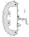
Eine andere Ausführungsform ist in Fig. 2 dargestellt. Hier ist die Innenseite des Oberteils (5) durch Aussparungen unterbrochen, die jeweils bis etwa zur halben Höhe des Oberteils geführt sind. Die Innenseite erhält dadurch die in Fig. 2 dargestellte Kontur mit den umlaufenden Nocken (5b), die unter den Profilrillen (6) angeordnet und ebenso wie die Flanken (5a) durch umlaufende Kerne (8) verstärkt sind. Die übrigen Ziffern in Fig. 2 haben die gleiche Bedeutung wie in Fig. 1.Another embodiment is shown in FIG. 2. Here, the inside of the upper part (5) is interrupted by recesses, which are each guided up to about half the height of the upper part. The inside is given the contour shown in FIG. 2 with the circumferential cams (5b), which are arranged under the profile grooves (6) and, like the flanks (5a), are reinforced by circumferential cores (8). The remaining digits in FIG. 2 have the same meaning as in FIG. 1.
In einer Abwandlung dieser Ausführungsform enthält der Reifen, wie in Fig. 3 dargestellt, zusätzlich einen auf der Felge (1a,b) aufsitzenden umlaufenden Stützring (10) mit mehreren über den Umfang verteilten Löchern (10a) zum Luftdurchlaß. Die Seitenwände des Stützrings liegen fest an der Innenwand der Reifenflanken (5a) an. Der Abstand zwischen Stützring und den Nocken (5b) ist so bemessen, daß im Normalbetrieb die Einfederungsbeweguhgen des Reifenoberteils (5) nicht beeinträchtigt werden. Der Stützring kann aus jedem dafür geeigneten Material, z.B. aus Kunststoff oder Metall, bestehen.In a modification of this embodiment, as shown in FIG. 3, the tire additionally contains a circumferential support ring (10) seated on the rim (1a, b) with a plurality of circumferential holes (10a) for the passage of air. The side walls of the support ring lie firmly against the inner wall of the tire flanks (5a). The distance between the support ring and the cams (5b) is such that the deflection movements of the upper tire part (5) are not impaired in normal operation. The support ring can be made of any suitable material, e.g. made of plastic or metal.
Fig. 4 zeigt einen derartigen Reifen bei Druckverlust. In diesem Fall setzen sich die Stütznocken auf den Stützring (10) auf, so daß die Lauffläche eine praktisch ebene Fläche bildet, während der Reifen sich in den Flanken nicht wesentlich verändert.Fig. 4 shows such a tire with loss of pressure. In this case, the support cams sit on the support ring (10) so that the tread forms a practically flat surface, while the tire does not change significantly in the flanks.
Auch bei den in Fig. 1 und 2 gezeigten Ausführungsformen erfährt bei einem Druckverlust lediglich das Reifenoberteil eine entsprechende Formänderung, während die starren Reifenflanken ihre Form im wesentlichen unverändert beibehalten. Durch das niedrige Höhen/Breiten-Verhältnis ist bei einem Druckverlust die Deformation des Reifens insgesamt so gering, daß er noch ausreichende Laufeigenschaften und Stabilität besitzt und auch in Kurven problemlos weitergefahren werden kann.Also in the embodiments shown in FIGS. 1 and 2, only the upper part of the tire undergoes a corresponding change in shape when there is a loss of pressure, while the rigid tire flanks retain their shape essentially unchanged. Due to the low height / width ratio, the deformation of the tire is so small when there is a loss of pressure that it still has sufficient running properties and stability and can be driven on even in bends without any problems.
Fig. 5 veranschaulicht die Herstellung des in Fig. 2 bzw. 3 dargestellten Reifens in einer üblichen Spritzpresse, die hier im Schnitt dargestellt ist. Es bedeuten:
- (11) Anspritzkanal für den Reifen ( 8) Drahtkerne des Reifens
- (14),(29) und (25) Lamellenhalterung für die Drahtkerne
- (17) und (19) Formoberteil
- (18) Federn
- (15) Segmente mit Schrägkonus zum Herausziehen des Formkörpers aus dem Profilgrund,
- (16) Hubkörper mit Schwalbenschwanznut, der durch die Befestigung (23) mit dem Formoberteil verbunden ist
- (24) Befestigungsteil zwischen den beiden Formoberteilen (17) und (19)
- (13) Formunterteile,
- (26) segmentierter Formkörper, Teile
- (27) und (28) Zentrierflansche für den segmentierten Kern,
- (21) Befestigung der Zentrierflansche,
- (22) Transporthaken,
- (12) Einsetzbüchse für den Anspritzkanal.
- (11) injection channel for the tire (8) wire cores of the tire
- (14), (29) and (25) slat holder for the wire cores
- (17) and (19) molded upper part
- (18) feathers
- (15) segments with angled cone for pulling the molded body out of the base of the profile,
- (16) lifting body with dovetail groove, which is connected to the upper part of the mold by the fastening (23)
- (24) fastening part between the two upper mold parts (17) and (19)
- (13) molded lower parts,
- (26) segmented molded body, parts
- (27) and (28) centering flanges for the segmented core,
- (21) attachment of the centering flanges,
- (22) transport hook,
- (12) Insert sleeve for the injection channel.
Im Formunterteil (13) wird in die Lamellenhalterung (14) der Drahtkern ( 8) eingelegt. Danach werden über den Transporthaken (22) die Innenteile (26,28,27,21) in die Form eingeführt. Auf die Lamellenhalterungen (25) werden vor dem Zusammenbau schon die anderen Drahtkerne (8) aufgebracht. Danach wird auf die obere Lamelle der letzte Drahtkern ( 8) aufgelegt. Im Anschluß hieran bewegen sich, über Kolben betätigt, die Bauteile (17,19,16 und 15) nach unten. Dabei wird über den Kegel (20) das Bauteil (15) soweit nach innen gedrückt, bis die Presse geschlossen ist. Anschließend wird über den Anspritzkanal (11) der Reifen gefüllt. Das öffnen der Pressen geschieht in umgekehrter Reihenfolge, wobei die Tellerfeder (18) noch die Hubwirkung verstärkt. Nachdem die Profilsegmente (15) über den Keil (20) nach außen zurückgefahren sind und die Presse geöffnet hat, werden wiederum über den Transporthaken (22) der Reifen und die inneren Formteile (21,28,27,26) herausgenommen. An einer zentralen Entformungsstelle wird dann der Reifen freigelegt, während ein zweiter bereits vorher montierter Kern in die Form eingebracht wird und der nächste Reifen in oben beschriebener Reihenfolge hergestellt wird. Die Heizung des Reifens erfolgt je nach verwendeter Kautschukmischung 5 bis 8 Minuten bei Temperaturen von 145-175°C.The wire core (8) is inserted into the lamella holder (14) in the lower mold part (13). Then the inner parts (26, 28, 27, 21) are inserted into the mold via the transport hook (22). The other wire cores (8) are already applied to the lamella brackets (25) before assembly. After that, go to the top The last wire core (8) is placed on the slat. Following this, the components (17, 19, 16 and 15), actuated by pistons, move downwards. The component (15) is pressed inwards over the cone (20) until the press is closed. The tire is then filled via the injection channel (11). The presses are opened in reverse order, with the plate spring (18) increasing the lifting effect. After the profile segments (15) have moved back outwards via the wedge (20) and the press has opened, the tires and the inner molded parts (21, 28, 27, 26) are again removed via the transport hook (22). The tire is then exposed at a central demolding point, while a second core which has already been assembled is introduced into the mold and the next tire is produced in the sequence described above. Depending on the rubber compound used, the tire is heated for 5 to 8 minutes at temperatures of 145-175 ° C.
Der Reifen muß nicht wie bei herkömmlichen Reifen aus mehreren Lagen unterschiedlichen Materials aufgebaut werden, sondern kann, abgesehen von den umlaufenden Draht- oder Textilverstärkungen, aus einem einheitlichen Kautschuk bzw. Kautschukgemisch hergestellt werden. Geeignet sind alle beliebigen Natur-oder Synthese-Kautschuke, deren Vulkanisate eine Shore-Härte von 55 bis 90 und einen Spannungswert von 100-200 kp/cm2 bei 300 % Dehnung aufweisen. Besonders geeignet sind: Naturkautschuk, Styrol-Butadien-Kautschuk, Polybutadien-Kautschuk und Ethylen-Propylen-Terpolymerisat-Kautschuk.The tire does not have to be constructed from several layers of different material as in conventional tires, but can, apart from the circumferential wire or textile reinforcements, be made from a uniform rubber or rubber mixture. All natural or synthetic rubbers are suitable, the vulcanizates of which have a Shore hardness of 55 to 90 and a tension value of 100-200 kp / cm 2 at 300% elongation. Particularly suitable are: natural rubber, styrene-butadiene rubber, polybutadiene rubber and ethylene Propylene terpolymer rubber.
Nachfolgend seien beispielhaft die Eigenschaften und Hauptbestandteile geeigneter Kautschukmischungen angegeben.


Für die Reifenflanken können jedoch auch spezielle Kautschukmischungen eingesetzt werden, die gegebenenfalls durch einen Zusatz von z.B. modifizierten Novolaken oder Glasfasern verstärkt sind und eine größere Shore-Härte besitzen.However, special rubber compounds can also be used for the tire flanks, which may be added by adding e.g. modified novolaks or glass fibers are reinforced and have a greater Shore hardness.
Nachfolgend seien beispielhaft die Eigenschaften und Hauptbestandteile derartiger Kautschukmischungen angegeben:


Claims (5)
Applications Claiming Priority (2)
| Application Number | Priority Date | Filing Date | Title |
|---|---|---|---|
| DE19813138582 DE3138582A1 (en) | 1981-09-29 | 1981-09-29 | TIRES FOR MOTOR VEHICLES |
| DE3138582 | 1981-09-29 |
Publications (1)
| Publication Number | Publication Date |
|---|---|
| EP0083391A2 true EP0083391A2 (en) | 1983-07-13 |
Family
ID=6142835
Family Applications (1)
| Application Number | Title | Priority Date | Filing Date |
|---|---|---|---|
| EP82108530A Withdrawn EP0083391A2 (en) | 1981-09-29 | 1982-09-16 | Tyre for vehicles |
Country Status (5)
| Country | Link |
|---|---|
| US (1) | US4467852A (en) |
| EP (1) | EP0083391A2 (en) |
| JP (1) | JPS5873403A (en) |
| CA (1) | CA1190129A (en) |
| DE (1) | DE3138582A1 (en) |
Cited By (2)
| Publication number | Priority date | Publication date | Assignee | Title |
|---|---|---|---|---|
| EP0192112A2 (en) * | 1985-02-16 | 1986-08-27 | Bayer Ag | Pneumatic tyre having emergency running characteristics |
| EP0139507B1 (en) * | 1983-10-11 | 1989-05-24 | Unisys Corporation | Island record films; fabrication |
Families Citing this family (13)
| Publication number | Priority date | Publication date | Assignee | Title |
|---|---|---|---|---|
| DE3345367A1 (en) * | 1983-12-15 | 1985-06-27 | Continental Gummi-Werke Ag, 3000 Hannover | VEHICLE WHEEL |
| GB8517959D0 (en) * | 1985-07-16 | 1985-08-21 | Sp Tyres Uk Ltd | Motor cycle tyres |
| US4823854A (en) * | 1986-01-27 | 1989-04-25 | Motor Wheel Corporation | Safety tire and rim combination with safety insert |
| US5000241A (en) * | 1989-05-09 | 1991-03-19 | Patecell Theodore C | Unitary bead-lock and run-flat roller support ring for pneumatic tires on two-part wheels |
| US5022450A (en) * | 1989-11-06 | 1991-06-11 | Motor Wheel Corporation | Safety tire and take-apart wheel construction |
| US5499669A (en) * | 1994-07-14 | 1996-03-19 | Deere & Company | Reinforced semi-pneumatic tire |
| US5533793A (en) * | 1995-03-17 | 1996-07-09 | Gleason Corporation | Agricultural tires and wheel assemblies therefore |
| DE19745409C2 (en) * | 1997-10-15 | 2002-06-20 | Continental Ag | Vehicle wheel with an emergency running support body |
| EP1227942B1 (en) * | 1999-09-29 | 2004-03-10 | Société de Technologie Michelin | Safety support with noise suppressor for vehicle wheel |
| US6499521B2 (en) | 2000-06-07 | 2002-12-31 | The Goodyear Tire & Rubber Company | Low aspect ratio pneumatic tire without sidewalls |
| US7086438B1 (en) | 2000-08-30 | 2006-08-08 | Vossberg Stephen M | Pneumatic tire having a stabilizing system for under-inflated conditions |
| US7726536B2 (en) * | 2004-04-02 | 2010-06-01 | Black & Decker Inc. | Upper bumper configuration for a power tool |
| CA2902079A1 (en) * | 2015-08-31 | 2017-02-28 | Tomo Bonac | Cushion tire |
Family Cites Families (3)
| Publication number | Priority date | Publication date | Assignee | Title |
|---|---|---|---|---|
| US485633A (en) * | 1892-11-08 | Cushion-tire and rim therefor | ||
| FR680856A (en) * | 1928-09-08 | 1930-05-07 | Rubber tire for vehicle wheels | |
| US2600033A (en) * | 1948-04-13 | 1952-06-10 | Hamlin Metal Products Company | Toy wheel and method of making |
-
1981
- 1981-09-29 DE DE19813138582 patent/DE3138582A1/en not_active Withdrawn
-
1982
- 1982-09-16 US US06/418,748 patent/US4467852A/en not_active Expired - Fee Related
- 1982-09-16 EP EP82108530A patent/EP0083391A2/en not_active Withdrawn
- 1982-09-24 JP JP57165134A patent/JPS5873403A/en active Pending
- 1982-09-27 CA CA000412278A patent/CA1190129A/en not_active Expired
Cited By (3)
| Publication number | Priority date | Publication date | Assignee | Title |
|---|---|---|---|---|
| EP0139507B1 (en) * | 1983-10-11 | 1989-05-24 | Unisys Corporation | Island record films; fabrication |
| EP0192112A2 (en) * | 1985-02-16 | 1986-08-27 | Bayer Ag | Pneumatic tyre having emergency running characteristics |
| EP0192112A3 (en) * | 1985-02-16 | 1987-12-16 | Bayer Ag | Pneumatic tyre having emergency running characteristics |
Also Published As
| Publication number | Publication date |
|---|---|
| JPS5873403A (en) | 1983-05-02 |
| DE3138582A1 (en) | 1983-04-07 |
| CA1190129A (en) | 1985-07-09 |
| US4467852A (en) | 1984-08-28 |
Similar Documents
| Publication | Publication Date | Title |
|---|---|---|
| EP0083391A2 (en) | Tyre for vehicles | |
| DE3218315C2 (en) | ||
| DE69824867T2 (en) | Run-flat tires with improved transition between bead and rim | |
| DE1729756A1 (en) | Method and apparatus for manufacturing pneumatic tires | |
| DE2522924A1 (en) | SAFETY TIRES FOR MOTOR VEHICLES AND METHOD OF MANUFACTURING THEREOF | |
| DE2449668A1 (en) | TIRE | |
| DE1505016A1 (en) | Method of making a pneumatic tire | |
| DE2627951A1 (en) | EXPANDABLE BLADDER FOR A TIRE BUILDING MACHINE FOR SINGLE-STAGE OR TWO-STAGE MANUFACTURING, IN PARTICULAR OF RADIAL-LAYER TIRES | |
| DE2944345A1 (en) | RUBBER SPRING TIRES AND METHOD FOR THE PRODUCTION THEREOF | |
| DE3101408A1 (en) | VEHICLE TIRE | |
| DE2423622A1 (en) | TIRE | |
| DE3008698A1 (en) | WHEEL RIM FOR TIRES | |
| DE2851765A1 (en) | TIRES FOR HIGH PAYLOADS | |
| DE2529597A1 (en) | SAFETY TIRES | |
| DE69812974T2 (en) | Construction of bead cores and bead fillers | |
| DE10332532A1 (en) | Pneumatic tires for passenger vehicles and process for producing these pneumatic tires | |
| EP0173670A2 (en) | Vehicle tyre | |
| DE69933021T2 (en) | HEAVY DUTY BELT TIRE | |
| EP0212333A2 (en) | Vehicle wheel | |
| DE2130263A1 (en) | tire | |
| DE102016211332A1 (en) | Process for producing a solid rubber tire and solid rubber tires produced by the process | |
| DE2228610A1 (en) | METHOD AND MOLD FOR MANUFACTURING CAST PNEUMATIC TIRES | |
| DE1912598A1 (en) | tire | |
| DE2156055A1 (en) | Tyre mould - with inflatable core of textile-reinforced elastomer | |
| DE4009500A1 (en) | Radial tyre with tread wear indicators - has wear indicators situated near parting lines of vulcanising die segments |
Legal Events
| Date | Code | Title | Description |
|---|---|---|---|
| PUAI | Public reference made under article 153(3) epc to a published international application that has entered the european phase |
Free format text: ORIGINAL CODE: 0009012 |
|
| 17P | Request for examination filed |
Effective date: 19820916 |
|
| AK | Designated contracting states |
Designated state(s): AT BE DE FR GB IT LU NL SE |
|
| STAA | Information on the status of an ep patent application or granted ep patent |
Free format text: STATUS: THE APPLICATION HAS BEEN WITHDRAWN |
|
| 18W | Application withdrawn |
Withdrawal date: 19840109 |
|
| R18W | Application withdrawn (corrected) |
Effective date: 19840109 |
|
| RIN1 | Information on inventor provided before grant (corrected) |
Inventor name: STUETTGEN, FRIEDEL Inventor name: IPPEN, JAKOB, DR. |