EP0082945B1 - Printing machine with a cylinder which can be coupled to a driving device - Google Patents
Printing machine with a cylinder which can be coupled to a driving device Download PDFInfo
- Publication number
- EP0082945B1 EP0082945B1 EP82110510A EP82110510A EP0082945B1 EP 0082945 B1 EP0082945 B1 EP 0082945B1 EP 82110510 A EP82110510 A EP 82110510A EP 82110510 A EP82110510 A EP 82110510A EP 0082945 B1 EP0082945 B1 EP 0082945B1
- Authority
- EP
- European Patent Office
- Prior art keywords
- printing machine
- ring
- piston
- cylinder
- bushing
- Prior art date
- Legal status (The legal status is an assumption and is not a legal conclusion. Google has not performed a legal analysis and makes no representation as to the accuracy of the status listed.)
- Expired
Links
Images
Classifications
-
- B—PERFORMING OPERATIONS; TRANSPORTING
- B41—PRINTING; LINING MACHINES; TYPEWRITERS; STAMPS
- B41F—PRINTING MACHINES OR PRESSES
- B41F13/00—Common details of rotary presses or machines
-
- B—PERFORMING OPERATIONS; TRANSPORTING
- B41—PRINTING; LINING MACHINES; TYPEWRITERS; STAMPS
- B41F—PRINTING MACHINES OR PRESSES
- B41F9/00—Rotary intaglio printing presses
- B41F9/06—Details
- B41F9/18—Auxiliary devices for exchanging forme cylinders
Definitions
- the invention relates to a printing press, in particular gravure printing press, with at least one cylinder which can be coupled via a clutch to a drive device, the clutch having a flexible, drivable sleeve which can be driven in the radial direction and which engages around a pin provided on the cylinder and on it by means of a of the bushing, consisting of plate rim-shaped against a ring bundle inclined to the axis of rotation perpendicular to the radial plane rings pack can be pressed, which is supported in the region of an end face in the axial direction and on the other hand can be subjected to force.
- the flexible bushing not only comprises the pin on the cylinder side, but also a pin which is located coaxially opposite the pin and is non-rotatably connected to the drive device.
- a ring set is assigned to each pin.
- These two ring packs are supported on the sides facing away from each other on stationary ring flanges and lie with the mutually facing sides on two disks which delimit a wedge-shaped ring groove in cross section and can be moved apart by means of balls penetrating into this ring groove to act on the two ring packs.
- a screw nut with a conical collar screwed onto an annular flange is provided to actuate the balls.
- This arrangement not only requires two ring assemblies assigned to the two pins, together with the support and displacement devices assigned to them, but also a very long sleeve that bridges the distance between the two pins and comprises both pins of sufficient length in the radial direction Area between the two pegs is also claimed on Torrsion.
- Torrsion Area between the two pegs is also claimed on Torrsion.
- US-A 4185539 shows a blocking device for a shaft or a piston rod with a slotted ring comprising the shaft or rod to be blocked, which has a conical outer contour and interacts with an actuating element which has a correspondingly conical inner contour and which acts to effect a blocking or Release of the shaft or rod is displaceable in the axial direction.
- this actuating element rests on the one hand on a plate spring and on the other hand delimits a pressure chamber which can be acted upon by a pressure medium.
- a high level of user friendliness is achieved.
- the known arrangement according to US-A 4185539 only allows a shaft or rod to be blocked, but not a coupling with another moving element. Quite apart from this, this known arrangement requires an actuating element which interacts with the slotted ring, which can also have an unfavorable effect on the construction effort.
- the clutch has a rotationally connected to the drive device housing, in which the coaxially arranged, provided on the cylinder side pin engages and with which the pin encompassing, flexible in the radial direction is connected and that on the The bushing received, assigned to the pin, can be acted upon on the side opposite its axial support by means of a spring arrangement which can be acted upon against its force acting on the ring packet by means of a piston which is displaceable in the axial direction in the housing and which can be connected to a pressure source and is opposite the spring arrangement Pressure chamber limited.
- the ring assembly By pressurizing the piston, the ring assembly, which compresses the sleeve when acted upon by the associated spring arrangement and thus establishes a non-positive connection between the pin provided on the cylinder side and the housing connected to the drive device, can be relieved and the pin provided on the cylinder side can be released.
- the measures according to the invention thus practically result in a clutch with which the rotational connection between the housing and the pin can be released or produced quickly, easily and reliably.
- the measures according to the invention ensure that the ring packet acting axial force, which is converted into a much higher radial force, has the same size each time the clutch is actuated, which also has an advantageous impact on reliability and ease of use.
- the measures according to the invention result in a very compact design, and the outer circumference of the cylindrical housing can also advantageously serve as a brake drum or receptacle for a brake drum.
- the housing can be provided on the cylinder side with a detachably fixed cover, to which the bushing surrounding the pin is preferably attached by molding. This ensures a reliable securing of the position of the bushing while at the same time ensuring a particularly simple embodiment.
- Another particularly advantageous measure can consist in that the bushing is provided with continuous slots extending from radial bores arranged in the region of its cover-side end, the clear width of which is smaller than the diameter of the respectively assigned bore. This results in a high pull-out strength in the area of the slot base and thus a long service life of the component having the bush.
- the structure and mode of operation of an intaglio printing machine are known per se and therefore require no further explanation in the present context.
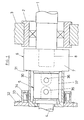
- the forme cylinder designated as a whole in FIG. 1 is accommodated with its ends in bearing shells 2 which, together with the forme cylinder 1, can be inserted into associated recesses in the machine side walls 3.
- a drive shaft 4 is provided, which is connected to the forme cylinder 1 via a joint 5 and a coupling 6 which can be released for installing and removing the forme cylinder 1.
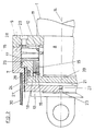
- the coupling 6, as shown in FIG. 2, consists of a pot-shaped housing 7 which is connected to the drive shaft 4 in a rotationally locking manner and into which a pin 8 which is coaxially attached to the forme cylinder 1 engages.
- a collar is provided to form a stop in the area of the cross-section of the spigot.
- the housing 7 and the pin 8 practically form two coupling halves which can be fixed to one another in a rotationally locking manner.
- the housing 7 is provided on the cylinder side with a removable cover 9, on which a bushing 10, which projects into the interior of the housing and comprises the pin 8, is formed, which, in order to bring about radial compliance, has two or more axially extending, from its free end to in In the area of the cross section 11 provided on the cover-side attachment cross section, extending slots 12 is provided.
- the diameter of the bores 11 is approximately 3 mm
- the clear width of the slots 12 is approximately 1 mm.
- the holes 11 ensure that the slots 12 cannot enlarge by tearing out the material in the area of the slot base.
- the molded on the screwed to the housing 7 cover 9 sleeve 10 can be pressed to transmit a torque from the housing 7 to the pin 8 by means of a ring package 13 received on its outer circumference on the pin 8.
- the ring assembly 13 consists of several plate rings, which are inclined in the shape of a plate against a radial plane perpendicular to the coupling axis 14 and vulcanized together to form a packet, which convert the axial force acting thereon into a radial force approximately in a ratio of 1: 5 when stressed in the axial direction.
- a plate spring 16 which consists of two plate elements and is arranged in the housing 7 and surrounds the bush 10, is provided to act on the ring packet 13.
- a displaceable actuating ring 17 is arranged between the plate spring 16 and the ring packet 13 to be acted upon by it.
- the ring packet 13 is secured in the axial direction by means of a stop opposite the actuating ring 17.
- a stop ring 18 is provided for this purpose, which is supported on a clamping ring 19 engaging in an assigned groove of the bush 10.
- the actuating ring 17 and in particular the stop ring 18 can be made of hardened material in order to achieve a high degree of dimensional stability and abrasion resistance.
- the rings 15 of the ring packet 13 are inclined with their outer circumference toward the actuating ring 17.
- the stop ring 18 made of hardened material is provided with sharp, unbroken edges.
- the ring assembly 13 can be relieved by means of a piston 20 arranged in the housing 7 so as to be displaceable in the axial direction, by means of which the plate spring 16 can be compressed against the force exerted on the ring assembly 13.
- the piston 20 delimits a pressure chamber 21 which can be acted upon by a pressure medium in order to displace the piston 20 against the force exerted by the plate spring 16.
- a centrally arranged threaded bore 22 is provided in the housing end wall adjacent to the piston 20, to which a pressure bore is indicated, which is only indicated here by its connecting nipple source leading supply line 23 can be connected.
- the supply line 23 can be guided centrally through the joint 5 and the drive shaft 4, the end of which opposite the joint 5 can be provided with a pressure medium feed designed as a rotary connection. Compressed air or preferably a hydraulic medium can be used as the pressure medium to act on the pressure chamber.
- the piston 20 is provided in the region of its end face facing away from the pressure chamber 21 with a blind bore 24 which receives the ring packet 13 and the area of the bush 10 and the pin 8 which receives it.
- the end face of the piston 20 facing away from the pressure chamber 21 can be set against the actuating ring 17.
- the diameter of the plate spring 16 is significantly larger than the diameter of the ring assembly 13. The same applies to the actuating ring 17.
- the piston 20 is provided on the spring side with an edge flange 25.
- the bore provided for receiving the piston 20 in the housing 7 is graduated accordingly.
- One or more sealing rings 26 arranged on the circumference of the piston 20 can be provided to seal the radially outer piston circumference from the associated housing bore.
- the housing wall is provided with a ventilation bore 27.
- the tension of the plate spring 16 can be adjusted by means of an adjusting device which has an adjusting ring 28 opposite the actuating ring 17, which is supported on adjusting screws 29 provided in the area of the housing cover 9. This also enables the ring set 13 and the plate spring 16 to be installed and removed in a de-energized state.
- the bush 30 is designed as a brake drum of a brake provided for braking the forme cylinder 1, which is provided with brake shoes 34 arranged in an annular housing 33 attached to the gearbox 32 on the drive shaft side, which can preferably be actuated by compressed air.
- the use of the brake drum as a centering sleeve results in a very compact design.
- flanges 35 are provided on the shaft side and on the housing side, which are each connected via a hinge pin 36 to a driver element 37 with an H-shaped cross section. This articulated connection enables the compensation of misalignments.
Abstract
Description
Die Erfindung betrifft eine Druckmaschine, insbesondere Tiefdruckmaschine, mit mindestens einem, über eine Kupplung mit einer Antriebseinrichtung kuppelbaren Zylinder, wobei die Kupplung eine mittels der Antriebseinrichtung antreibbare, in radialer Richtung nachgiebige Büchse aufweist, die einen zylinderseitige vorgesehenen Zapfen umgreift und an diesen mittels eines auf der Büchse aufgenommenen, aus tellerrandförmig gegen eine zur Drehachse lotrechte Radialebene schräg geneigten Ringen bestehenden Ringpakets anpreßbar ist, das im Bereich einer Stirnseite in axialer Richtung abgestützt und andererseits kraftbeaufschlagbar ist.The invention relates to a printing press, in particular gravure printing press, with at least one cylinder which can be coupled via a clutch to a drive device, the clutch having a flexible, drivable sleeve which can be driven in the radial direction and which engages around a pin provided on the cylinder and on it by means of a of the bushing, consisting of plate rim-shaped against a ring bundle inclined to the axis of rotation perpendicular to the radial plane rings pack can be pressed, which is supported in the region of an end face in the axial direction and on the other hand can be subjected to force.
Eine Anordnung dieser Art ist aus der DE-A 2402101 bekannt. Bei dieser bekannten Anordnung umfaßt die nachgiebige Büchse nicht nur den zylinderseitigen Zapfen, sondern auch einen diesem koaxial gegenüberliegenden, mit der Antriebseinrichtung drehfest verbundenen Zapfen. Beiden Zapfen ist jeweils ein Ringpaket zugeordnet. Diese beiden Ringpakete sind an den voneinander abgewandten Seiten an stationären Ringflanschen abgestützt und liegen mit den einander zugewandten Seiten an zwei Scheiben an, die eine im Querschnitt keilförmige Ringnut begrenzen und mittels in diese Ringnut eindringender Kugeln zur Beaufschlagung der beiden Ringpakete auseinandergefahren werden können. Zur Betätigung der Kugeln ist eine auf einen Ringflansch aufgeschraubte Schraubmutter mit konischem Kragen vorgesehen. Diese bekannte Anordnung erfordert ersichtlich einen hohen Bedienungsaufwand zur Betätigung der Kupplung in Ein- bzw. Auskuppelrichtung, da die mit den Kugeln zusammenwirkende Schraubmutter von Hand betätigt werden muß. Ein weiterer Nachteil der bekannten Anordnung ist darin zu sehen, daß hier die auf die Ringpakete ausgeübte Kraft und damit die zur Herstellung einer drehschlüssigen Verbindung zwischen Antriebseinrichtung und Zylinder wirksame Kraft vom Anzugsmoment der auf die Kugeln wirkenden Schraubmutter abhängig ist, was im Hinblick auf erwünschte konstante Verhältnisse ebenfalls negativ auf den Bedienungsaufwand durchschlägt. Als weiterer Nachteil kommt hinzu, daß die bekannte Anordnung gemäß DE-A 24 02 101 auch einen sehr hohen baulichen Aufwand erfordert. Diese Anordnung benötigt nämlich nicht nur zwei den beiden Zapfen zugeordnete Ringpakete samt den diesen zugeordneten Abstütz- und Verschiebeeinrichtungen, sondern auch eine sehr lange, den Abstand zwischen den beiden Zapfen überbrückende und beide Zapfen auf ausreichender Länge umfassende, in radialer Richtung nachgiebige Büchse, die im Bereich zwischen den beiden Zapfen zudem noch auf Torrsion beansprucht wird. Hinzu kommt, daß sich bei der bekannten Anordnung mit zwei einander gegenüberliegenden, in die nachgiebige Büchse eingreifenden Zapfen auch eine sehr große Baulänge in axialer Richtung ergiebt.An arrangement of this type is known from DE-A 2402101. In this known arrangement, the flexible bushing not only comprises the pin on the cylinder side, but also a pin which is located coaxially opposite the pin and is non-rotatably connected to the drive device. A ring set is assigned to each pin. These two ring packs are supported on the sides facing away from each other on stationary ring flanges and lie with the mutually facing sides on two disks which delimit a wedge-shaped ring groove in cross section and can be moved apart by means of balls penetrating into this ring groove to act on the two ring packs. A screw nut with a conical collar screwed onto an annular flange is provided to actuate the balls. This known arrangement obviously requires a high level of operating effort for actuating the coupling in the coupling or decoupling direction, since the screw nut cooperating with the balls must be actuated by hand. Another disadvantage of the known arrangement can be seen in the fact that here the force exerted on the ring assemblies and thus the force effective to produce a rotational connection between the drive device and the cylinder is dependent on the tightening torque of the screw nut acting on the balls, which is constant in view of the desired Conditions also have a negative impact on the operating effort. Another disadvantage is that the known arrangement according to DE-A 24 02 101 also requires a very high level of structural complexity. This arrangement not only requires two ring assemblies assigned to the two pins, together with the support and displacement devices assigned to them, but also a very long sleeve that bridges the distance between the two pins and comprises both pins of sufficient length in the radial direction Area between the two pegs is also claimed on Torrsion. In addition, in the known arrangement with two opposite pins which engage in the flexible bushing, there is also a very large overall length in the axial direction.
Die US-A 4185539 zeigt eine Blockiereinrichtung für eine Welle oder eine Kolbenstange mil einem die zu blokkierende Welle oder Stange umfassenden, geschlitzten Ring, der eine konische Außenkontur aufweist und mit einem eine entsprechend konische innenkontur aufweisenden Betätigungselement zusammenwirkt, das zur Bewirkung einer Blockierung bzw. Freigabe der Welle bzw. Stange in axialer Richtung verschiebbar ist. Bei einer Ausführung liegt dieses Betätigungselement einerseits an einer Tellerfeder an und begrenzt andererseits einen mit einem Druckmittel beaufschlagbaren Druckraum. Hierdurch wird zwar eine hohe Bedienungsfreundlichkeit erreicht. Die bekannte Anordnung gemäß US-A 4185539 ermöglicht jedoch lediglich eine Blockierung einer Welle bzw. Stange, jedoch keine Kupplung mit einem anderen bewegten Organ. Ganz abgesehen davon benötigt diese bekannte Anordnung ein mit dem geschlitzten Ring zusammenwirkendes Betätigungselement, was sich ebenfalls ungünstig auf den Bauaufwand auswirken kann.US-A 4185539 shows a blocking device for a shaft or a piston rod with a slotted ring comprising the shaft or rod to be blocked, which has a conical outer contour and interacts with an actuating element which has a correspondingly conical inner contour and which acts to effect a blocking or Release of the shaft or rod is displaceable in the axial direction. In one embodiment, this actuating element rests on the one hand on a plate spring and on the other hand delimits a pressure chamber which can be acted upon by a pressure medium. As a result, a high level of user friendliness is achieved. However, the known arrangement according to US-A 4185539 only allows a shaft or rod to be blocked, but not a coupling with another moving element. Quite apart from this, this known arrangement requires an actuating element which interacts with the slotted ring, which can also have an unfavorable effect on the construction effort.
Hiervon ausgehend ist es daher die Aufgabe der vorliegenden Erfindung, eine Anordnung eingangs erwähnter Art mit einfachen Mitteln so zu verbessern, daß eine hohe Bedienungsfreundlichkeit und gleichzeitig eine hohe Funktionssicherheit gewährleistet sind.Proceeding from this, it is therefore the object of the present invention to improve an arrangement of the type mentioned at the beginning with simple means in such a way that a high level of user-friendliness and at the same time a high level of functional reliability are ensured.
Diese Aufgabe wird erfindungsgemäß dadurch gelöst, daß die Kupplung ein drehschlüssig mit der Antriebseinrichtung verbundenes Gehäuse aufweist, in welches der koaxial hierzu angeordnete, zylinderseitig vorgesehene Zapfen eingreift und mit dem die den Zapfen umfassende, in radialer Richtung nachgiebige Büchse verbunden ist und daß das auf der Büchse aufgenommene, dem Zapfen zugeordnete Ringpaket auf der seiner axialen Abstützung gegenüberliegenden Seite mittels einer Federanordnung beaufschlagbar ist, die entgegen ihrer auf das Ringpaket wirkenden Kraft mittels eines im Gehäuse in axialer Richtung verschiebbaren Kolben beaufschlagbar ist, der eine der federanordnung gegenüberliegende, an eine Druckquelle anschließbare Druckkammer begrenzt.This object is achieved in that the clutch has a rotationally connected to the drive device housing, in which the coaxially arranged, provided on the cylinder side pin engages and with which the pin encompassing, flexible in the radial direction is connected and that on the The bushing received, assigned to the pin, can be acted upon on the side opposite its axial support by means of a spring arrangement which can be acted upon against its force acting on the ring packet by means of a piston which is displaceable in the axial direction in the housing and which can be connected to a pressure source and is opposite the spring arrangement Pressure chamber limited.
Durch Druckbeaufschlagung des Kolbens ist das Ringpaket, das bei Beaufschlagung durch die zugeordnete Federanordnung die Büchse zusammendrückt und damit eine kraftschlüssige Verbindung zwischen dem zylinderseitig vorgesehenen Zapfen und dem mit der Antriebseinrichtung verbundenen Gehäuse herstellt, entlastbar und damit der zylinderseitig vorgesehene Zapfen freigebbar. Die erfindungsgemäßen Maßnahmen ergeben somit praktisch eine Schaltkupplung, mit welcher die drehschlüssige Verbindung zwischen Gehäuse und Zapfen schnell, einfach und zuverlässig lösbar bzw. herstellbar ist. Außerdem wird durch die erfindungsgemäßen Maßnahmen sichergestellt, daß die auf das Ringpaket wirkende Axialkraft, die von diesem in eine um ein Vielfaches höhere Radialkraft umgesetzt wird, bei jeder Betätigung der Kupplung dieselbe Größe hat, was ebenfalls vorteilhaft auf die Zuverlässigkeit und die Bedienungsfreundlichkeit durchschlägt. Außerdem ergeben die erfindungsgemäßen Maßnahmen eine sehr kompakte Bauweise, wobei zudem der Außenumfang des zylindrischen Gehäuses in vorteilhafter Weise als Bremstrommel bzw. Aufnahme für eine Bremstrommel dienen kann.By pressurizing the piston, the ring assembly, which compresses the sleeve when acted upon by the associated spring arrangement and thus establishes a non-positive connection between the pin provided on the cylinder side and the housing connected to the drive device, can be relieved and the pin provided on the cylinder side can be released. The measures according to the invention thus practically result in a clutch with which the rotational connection between the housing and the pin can be released or produced quickly, easily and reliably. In addition, the measures according to the invention ensure that the ring packet acting axial force, which is converted into a much higher radial force, has the same size each time the clutch is actuated, which also has an advantageous impact on reliability and ease of use. In addition, the measures according to the invention result in a very compact design, and the outer circumference of the cylindrical housing can also advantageously serve as a brake drum or receptacle for a brake drum.
Gemäß einer vorteilhaften Weiterbildung des übergeordneten Maßnahmen kann das Gehäuse zylinderseitig mit einem abnehmbar festgelegten Deckel versehen sein, an dem die den Zapfen umgebende Büchse vorzugsweise durch Anformung befestigt ist. Hierdurch ist eine zuverlässige Lagesicherung der Büchse bei gleichzeitig gewährleisteter, besonders einfacher Ausführungsform sichergestellt.According to an advantageous development of the superordinate measures, the housing can be provided on the cylinder side with a detachably fixed cover, to which the bushing surrounding the pin is preferably attached by molding. This ensures a reliable securing of the position of the bushing while at the same time ensuring a particularly simple embodiment.
Eine weitere besonders vorteilhafte Maßnahme kann darin bestehen, daß die Büchse mit durchgehenden, von im Bereich ihres deckelseitigen Endes angeordneten Radialbohrungen ausgehenden Schlitzen versehen ist, deren lichte Weite kleiner als der Durchmesser der jeweils zugeordneten Bohrung ist. Hierdurch ergibt sich eine hohe Ausreißfestigkeit im Bereich des Schlitzgrundes und damit eine hohe Standzeit des die Büchse aufweisenden Bauteils.Another particularly advantageous measure can consist in that the bushing is provided with continuous slots extending from radial bores arranged in the region of its cover-side end, the clear width of which is smaller than the diameter of the respectively assigned bore. This results in a high pull-out strength in the area of the slot base and thus a long service life of the component having the bush.
Weitere vorteilhafte Ausgestaltungen und zu bevorzugende Weiterbildungen der übergeordneten Maßnahmen ergeben sich aus der nachstehenden Beschreibung eines Ausführungsbeispiels anhand der Zeichnung in Verbindung mit den restlichen Unteransprüchen.Further advantageous refinements and preferred further developments of the superordinate measures result from the following description of an exemplary embodiment with reference to the drawing in conjunction with the remaining subclaims.
In der Zeichnung zeigen :
Figur 1 eine Teilansicht eines mit einer Antriebswelle gekuppelten Formzylinders einer Tiefdruckmaschine undFigur 2 einen Längsschnitt durch die Kupplung der Anordnung gemäß Fig. 1.
- 1 shows a partial view of a forme cylinder coupled to a drive shaft of a gravure printing machine and
- FIG. 2 shows a longitudinal section through the coupling of the arrangement according to FIG. 1.
Der Aufbau und die Wirkungsweise einer Tiefdruckmaschine sind an sich bekannt und bedürfen daher im vorliegenden Zusammenhang keiner näheren Erläuterung mehr. Der in Fig. 1 als Ganzes mit 1 bezeichnete Formzylinder ist mit seinen Enden in Lagerschalen 2 aufgenommen, die zusammen mit dem Formzylinder 1 in zugeordnete Ausnehmungen der Maschinenseitenwände 3 einführbar sind. Zum Antrieb des Formzylinders 1 ist eine Antriebswelle 4 vorgesehen, die mit dem Formzylinder 1 über ein Gelenk 5 und eine zum Ein- und Ausbau des Formzylinders 1 lösbare Kupplung 6 verbunden ist.The structure and mode of operation of an intaglio printing machine are known per se and therefore require no further explanation in the present context. The forme cylinder designated as a whole in FIG. 1 is accommodated with its ends in
Die Kupplung 6 besteht, wie Fig. 2 zeigt, aus einem mit der Antriebswelle 4 drehschlüssig verbundenen, topfförmigen Gehäuse 7, in das ein an den Formzylinder 1 koaxial hierzu angesetzter Zapfen 8 eingreift. Zur Bildung eines Anschlags ist im Bereich des Zapfenansatzquerschnitts ein Bund vorgesehen. Das Gehäuse 7 und der Zapfen 8 bilden praktisch zwei Kupplungshälften, die drehschlüssig aneinander festiegbar sind. Das Gehäuse 7 ist zylinderseitig mit einem abnehmbaren Deckel 9 versehen, an den eine in das Gehäuseinnere hineinragende, den Zapfen 8 umfassende Büchse 10 angeformt ist, die zur Bewerkstelligung einer radialen Nachgiebigkeit mit zwei oder mehreren, axial verlaufenden, von ihrem freien Ende bis zu im Bereich ihres deckelseitigen Ansatzquerschnitts vorgesehenen Radialbohrungen 11 sich erstreckenden Schlitzen 12 versehen ist. Der Durchmesser der Bohrungen 11 beträgt etwa 3 mm, die lichte Weite der Schlitze 12 etwa 1 mm. Die Bohrungen 11 stellen sicher, daß die Schlitze 12 sich nicht durch Ausreißen des Materials im Bereich des Schlitzgrundes vergrößern können. Die an den mit dem Gehäuse 7 verschraubten Deckel 9 angeformte Büchse 10 ist zur Übertragung eines Drehmoments vom Gehäuse 7 auf den Zapfen 8 mittels eines auf ihrem Außenumfang aufgenommenen Ringpakets 13 an den zapfen 8 anpreßbar. Das Ringpaket 13 besteht aus mehreren, tellerrandförmig gegen eine zur Kupplungsachse 14 lotrechte Radialebene geneigten, zu einem Paket zusammenvulkanisierten Metallringen 15, die bei Beanspruchung in axialer Richtung die hierauf wirkende Axialkraft etwa im Verhältnis 1 : 5 in eine Radialkraft umsetzen.The
Zur Beaufschlagung des Ringpakets 13 ist eine hier aus zwei Tellerelementen bestehende, im Gehäuse 7 angeordnete, die Büchse 10 umgebende Tellerfeder 16 vorgesehen. Zwischen der Tellerfeder 16 und dem hiervon zu beaufschlagenden Ringpaket 13 ist ein verschiebbarer Betätigungsring 17 angeordnet. Das Ringpaket 13 ist mittels eines dem Betätigungsring 17 gegenüberliegenden Anschlags in axialer Richtung gesichert. Im dargestellten Ausführungsbeispiel ist hierzu ein Anschlagring 18 vorgesehen, der an einen in eine zugeordnete Nut der Büchse 10 eingreifenden Spannring 19 abgestützt ist. Der Betätigungsring 17 und insbesondere der Anschlagring 18 können zur Erzielung einer hohen Formstabilität und Abriebfestigkeit aus gehärtetem Material bestehen. Die Ringe 15 des Ringpakets 13 sind im dargestellten Ausführungsbeispiel mit ihrem äußeren Umfang zum Betätigungsring 17 hin geneigt. Zur Vermeidung eines Festfressens des im Bereich der radial inneren Kante des Anschlagrings 18 an diesem anliegenden Ringpakets 13 und zur Gewährleistung einer exakten Lagesicherung ist der aus gehärtetem Material bestehende Anschlagring 18 mit scharfen, ungebrochenen Kanten versehen. Das Ringpaket 13 ist mittels eines im Gehäuse 7 in axialer Richtung verschiebbar angeordneten Kolbens 20 entlastbar, mittels dessen die Tellerfeder 16 entgegen der auf das Ringpaket 13 ausgeübten Kraft zusammendrückbar ist. Der Kolben 20 begrenzt eine Druckkammer 21, die zum Verschieben des Kolbens 20 entgegen der von der Tellerfeder 16 ausgeübten Kraft mit einem Druckmittel beaufschlagbar ist. Hierzu ist in der dem Kolben 20 benachbarten Gehäusestirnwand eine zentral angeordnete Gewindebohrung 22 vorgesehen, an die eine hier lediglich durch ihren Anschlußnippel angedeutete, zu einer Druckquelle führende Versorgungsleitung 23 anschließbar ist. Die Versorgungsleitung 23 kann zentral durch das Gelenk 5 und die Antriebswelle 4 hindurchgeführt sein, deren dem Gelenk 5 gegenüberliegendes Ende mit einer als Drehverbindung ausgebildeten Druckmittelzuführung versehen sein kann. Als Druckmittel zur Beaufschlagung der Druckkammer kann Druckluft oder vorzugsweise ein Hydraulikmittel Verwendung finden.A
Der Kolben 20 ist im Bereich seiner von der Druckkammer 21 abgewandten Stirnseite mit einer Sackbohrung 24 versehen, welche das Ringpaket 13 und den dieses aufnehmenden Bereich der Büchse 10 und des Zapfens 8 aufnimmt. Die von der Druckkammer 21 abgewandte Stirnseite des Kolbens 20 ist an den Betätigungsring 17 anstellbar. Der Durchmesser der Tellerfeder 16 ist wesentlich größer als der Durchmesser des Ringpakets 13. Dasselbe gilt für den Betätigungsring 17. Zur Anpassung an diese radiale Weite ist der Kolben 20 federseitig mit einem Randflansch 25 versehen. Die zur Aufnahme des Kolbens 20 im Gehäuse 7 vorgesehene Bohrung ist dementsprechend abgestuft. Zur Abdichtung des radial äußeren Kolbenumfangs gegenüber der zugeordneten Gehäusebohrung können einer oder mehrere, am Umfang des Kolbens 20 angeordnete Dichtringe 26 vorgesehen sein. Zur Gewährleistung einer ordnungsgemäßen Be- und Entlüftung des durch die Gehäusestufe gebildeten, von der Druckkammer 21 abgesetzten Bohrungsabschnitt ist die Gehäusewandung mit einer Entlüftungsbohrung 27 versehen. Die Spannung der Tellerfeder 16 ist mittels einer Stelleinrichtung einstellbar, die einen dem Betätigungsring 17 gegenüberliegenden Stellring 28 aufweist, der an im Bereich des Gehäusedeskels 9 vorgesehenen Stellschrauben 29 abgestützt ist. Dies ermöglicht auch einen Ein- und Ausbau des Ringpakets 13 und der Tellerfeder 16 in spannungslosem Zustand.The
In der der Fig. 2 zugrunde liegenden Stellung des Kolbens 20 ist die Tellerfeder 16 zusammengeschoben und damit das Ringpaket 13 entlastet. Die Büchse 10 ist dabei vom Zapfen 8 gelöst, so daß dieser bei der Entnahme des zugehörigen Zylinders 1 aus dem Gehäuse 7 herausgefahren werden kann. Der Hub des Kolbens 20 wird dabei einfach durch die vordere Stirnseite der Büchse 10 begrenzt. Zur Zentrierung des gelenkig mit der Antriebswelle 4 verbundenen Gehäuses 7 bei herausgefahrenem Zapfen 8 ist, wie Fig. 1 am besten erkennen läßt, eine das Gelenk 5 übergreifende, an der Antriebswelle 4 befestigte Büchse 30 vorgesehen, die mit ihrem von der Antriebswelle 4 abgewandten Stirnrand das Gehäuse 7 übergreift, das einen der Büchse 30 zugeordneten, angedrehten Bund 31 aufweisen kann. Im dargestellten Ausführungsbeispiel ist die Büchse 30 als Bremstrommel einer zum Abbremsen des Formzylinders 1 vorgesehenen Bremse ausgebildet, die mit in einem am antriebswellenseitigen Getriebekasten 32 befestigten Ringgehäuse 33 angeordneten, vorzugsweise durch Druckluft betätigbaren Bremsbacken 34 versehen ist. Die Verwendung der Bremstrommel als Zentrierbüchse ergibt eine sehr kompakte Bauweise. Zur Übertragung des Drehmoments von der Antriebswelle 4 auf das Gehäuse 7 sind wellenseitig und gehäuseseitig angeflanschte Laschen 35 vorgesehen, die über jeweils einen Gelenkbolzen 36 mit einem im Querschnitt H-förmigen Mitnehmerelement 37 verbunden sind. Diese gelenkige Verbindung ermöglicht den Ausgleich von Fluchtungsfehlern.In the position of the
Claims (10)
Priority Applications (1)
| Application Number | Priority Date | Filing Date | Title |
|---|---|---|---|
| AT82110510T ATE17932T1 (en) | 1981-12-24 | 1982-11-12 | PRINTING PRESS WITH A CYLINDER CONNECTABLE TO A DRIVE DEVICE. |
Applications Claiming Priority (2)
| Application Number | Priority Date | Filing Date | Title |
|---|---|---|---|
| DE19818137709U DE8137709U1 (en) | 1981-12-24 | 1981-12-24 | PRINTING MACHINE |
| DE8137709U | 1981-12-24 |
Publications (2)
| Publication Number | Publication Date |
|---|---|
| EP0082945A1 EP0082945A1 (en) | 1983-07-06 |
| EP0082945B1 true EP0082945B1 (en) | 1986-02-12 |
Family
ID=6734204
Family Applications (1)
| Application Number | Title | Priority Date | Filing Date |
|---|---|---|---|
| EP82110510A Expired EP0082945B1 (en) | 1981-12-24 | 1982-11-12 | Printing machine with a cylinder which can be coupled to a driving device |
Country Status (4)
| Country | Link |
|---|---|
| US (1) | US4453464A (en) |
| EP (1) | EP0082945B1 (en) |
| AT (1) | ATE17932T1 (en) |
| DE (2) | DE8137709U1 (en) |
Families Citing this family (6)
| Publication number | Priority date | Publication date | Assignee | Title |
|---|---|---|---|---|
| DE3715536A1 (en) * | 1987-05-09 | 1988-12-01 | Roland Man Druckmasch | STORAGE FOR A PRINTING CYLINDER |
| DE4010192A1 (en) * | 1990-03-30 | 1991-10-02 | Roland Man Druckmasch | DEVICE FOR BENDING A ROLLER |
| DE4013462A1 (en) * | 1990-04-27 | 1991-11-07 | Heidelberger Druckmasch Ag | DEVICE FOR LACQUERING PRINTED SHEETS ON PRINTING MACHINES |
| DE10066068A1 (en) * | 2000-05-17 | 2002-09-26 | Koenig & Bauer Ag | Drive of a rotating component |
| DE10227448A1 (en) * | 2002-06-20 | 2004-01-15 | Widia Gmbh | Rotary printer detachable connector device for detachable connection of a motor drive shaft and a cylinder shaft forms a multi-part tension device with a hollow shaft and a spigot |
| DE10329429B4 (en) * | 2003-07-01 | 2006-10-12 | Koenig & Bauer Ag | Drives of a printing machine |
Family Cites Families (7)
| Publication number | Priority date | Publication date | Assignee | Title |
|---|---|---|---|---|
| FR1066771A (en) * | 1951-12-01 | 1954-06-09 | Zahnradfabrik Friedrichshafen | Friction coupling |
| US3011608A (en) * | 1960-12-20 | 1961-12-05 | Quinten A Hansen | Fluid pressure operated clutch having an integral and non-rotatable cylinder and piston assembly |
| DE1804857B2 (en) * | 1968-10-24 | 1971-11-25 | Hänchen, Siegfried, 7304 Ruit | DEVICE FOR CLAMPING AN AXIALLY MOVABLE PISTON ROD |
| US3791499A (en) * | 1972-01-03 | 1974-02-12 | J Ryan | Clutch |
| DE2402101C3 (en) * | 1974-01-17 | 1978-09-14 | Maschinenfabrik Augsburg-Nuernberg Ag, 8900 Augsburg | Device for connecting the form cylinder of a rotary printing press to its drive shaft |
| US4185539A (en) * | 1977-03-07 | 1980-01-29 | Andrew Stratienko | Locking device for hydraulic actuator |
| US4131185A (en) * | 1977-06-03 | 1978-12-26 | Dana Corporation | Friction clutch synchronizer with resilient gear coupling |
-
1981
- 1981-12-24 DE DE19818137709U patent/DE8137709U1/en not_active Expired
-
1982
- 1982-11-12 EP EP82110510A patent/EP0082945B1/en not_active Expired
- 1982-11-12 AT AT82110510T patent/ATE17932T1/en not_active IP Right Cessation
- 1982-11-12 DE DE8282110510T patent/DE3269097D1/en not_active Expired
- 1982-11-12 US US06/440,971 patent/US4453464A/en not_active Expired - Fee Related
Also Published As
| Publication number | Publication date |
|---|---|
| US4453464A (en) | 1984-06-12 |
| DE8137709U1 (en) | 1982-06-03 |
| DE3269097D1 (en) | 1986-03-27 |
| ATE17932T1 (en) | 1986-02-15 |
| EP0082945A1 (en) | 1983-07-06 |
Similar Documents
| Publication | Publication Date | Title |
|---|---|---|
| DE3340333C1 (en) | Swash plate axial piston pump | |
| DE3146992A1 (en) | CLUTCH UNIT | |
| EP3189235B1 (en) | Progressive cavity pump | |
| DE19831694A1 (en) | Printing unit for a web-fed rotary printing press | |
| EP0425936A2 (en) | Device for quickly registering, fixing and tensioning printing plates | |
| EP1179149B1 (en) | Sealing device for a piston which is subjected to the action of a pressure medium and which is arranged in a working cylinder | |
| EP0082945B1 (en) | Printing machine with a cylinder which can be coupled to a driving device | |
| DE3201140A1 (en) | FAN COUPLING | |
| DE2947242A1 (en) | HYDRAULICALLY OPERATED FRICTION CLUTCH | |
| EP0881072B1 (en) | Drive for a wiping cylinder in a die stamping press | |
| EP0209869B1 (en) | Pivoting device for a centrifugal traction assembly of a vehicle | |
| DE3008049A1 (en) | DEVICE FOR SHOCK ABSORBING ON A PRESS | |
| DE2510852C3 (en) | Disc refiner for shredding fiber material | |
| DE4435226C2 (en) | Device for gear train separation, i.e. for clamping or releasing a clamp connection of two gear wheels | |
| DE19754491A1 (en) | Vehicle multiple disk brake with piston unit | |
| DE2452221A1 (en) | Hydrodynamic working cylinder - incorporates sealing sleeve for working piston with gap between sleeve and cylinder | |
| EP0713023A1 (en) | Shaft coupling | |
| DE2233875A1 (en) | MECHANICAL SCREW PRESS | |
| DE10245235B4 (en) | clamping set | |
| DE2141857A1 (en) | Fluid pressure operated disc brake | |
| EP0088232B1 (en) | Control element, particularly a spring-actuated brake or coupling | |
| DE3801348A1 (en) | Friction clutch with operating device | |
| DE3744284A1 (en) | Coupling device for the releasable connection of two parts to one another | |
| EP0141189A1 (en) | Inking unit for a rotary printing machine | |
| DE4330634A1 (en) | Device for clamping an axially movable rod |
Legal Events
| Date | Code | Title | Description |
|---|---|---|---|
| PUAI | Public reference made under article 153(3) epc to a published international application that has entered the european phase |
Free format text: ORIGINAL CODE: 0009012 |
|
| AK | Designated contracting states |
Designated state(s): AT BE CH DE FR GB IT LI LU NL SE |
|
| 17P | Request for examination filed |
Effective date: 19831223 |
|
| GRAA | (expected) grant |
Free format text: ORIGINAL CODE: 0009210 |
|
| AK | Designated contracting states |
Designated state(s): AT BE CH DE FR GB IT LI LU NL SE |
|
| REF | Corresponds to: |
Ref document number: 17932 Country of ref document: AT Date of ref document: 19860215 Kind code of ref document: T |
|
| ITF | It: translation for a ep patent filed |
Owner name: ORGANIZZAZIONE D'AGOSTINI |
|
| REF | Corresponds to: |
Ref document number: 3269097 Country of ref document: DE Date of ref document: 19860327 |
|
| ET | Fr: translation filed | ||
| PLBE | No opposition filed within time limit |
Free format text: ORIGINAL CODE: 0009261 |
|
| STAA | Information on the status of an ep patent application or granted ep patent |
Free format text: STATUS: NO OPPOSITION FILED WITHIN TIME LIMIT |
|
| 26N | No opposition filed | ||
| ITTA | It: last paid annual fee | ||
| PGFP | Annual fee paid to national office [announced via postgrant information from national office to epo] |
Ref country code: GB Payment date: 19920928 Year of fee payment: 11 |
|
| PGFP | Annual fee paid to national office [announced via postgrant information from national office to epo] |
Ref country code: FR Payment date: 19921022 Year of fee payment: 11 |
|
| PGFP | Annual fee paid to national office [announced via postgrant information from national office to epo] |
Ref country code: SE Payment date: 19921027 Year of fee payment: 11 Ref country code: LU Payment date: 19921027 Year of fee payment: 11 Ref country code: CH Payment date: 19921027 Year of fee payment: 11 |
|
| PGFP | Annual fee paid to national office [announced via postgrant information from national office to epo] |
Ref country code: AT Payment date: 19921028 Year of fee payment: 11 |
|
| PGFP | Annual fee paid to national office [announced via postgrant information from national office to epo] |
Ref country code: BE Payment date: 19921029 Year of fee payment: 11 |
|
| PGFP | Annual fee paid to national office [announced via postgrant information from national office to epo] |
Ref country code: DE Payment date: 19921119 Year of fee payment: 11 |
|
| PGFP | Annual fee paid to national office [announced via postgrant information from national office to epo] |
Ref country code: NL Payment date: 19921130 Year of fee payment: 11 |
|
| EPTA | Lu: last paid annual fee | ||
| PG25 | Lapsed in a contracting state [announced via postgrant information from national office to epo] |
Ref country code: LU Free format text: LAPSE BECAUSE OF NON-PAYMENT OF DUE FEES Effective date: 19931112 Ref country code: GB Effective date: 19931112 Ref country code: AT Effective date: 19931112 |
|
| PG25 | Lapsed in a contracting state [announced via postgrant information from national office to epo] |
Ref country code: SE Effective date: 19931113 |
|
| PG25 | Lapsed in a contracting state [announced via postgrant information from national office to epo] |
Ref country code: LI Effective date: 19931130 Ref country code: CH Effective date: 19931130 Ref country code: BE Effective date: 19931130 |
|
| BERE | Be: lapsed |
Owner name: ALBERT-FRANKENTHAL A.G. Effective date: 19931130 |
|
| PG25 | Lapsed in a contracting state [announced via postgrant information from national office to epo] |
Ref country code: NL Effective date: 19940601 |
|
| GBPC | Gb: european patent ceased through non-payment of renewal fee |
Effective date: 19931112 |
|
| NLV4 | Nl: lapsed or anulled due to non-payment of the annual fee | ||
| PG25 | Lapsed in a contracting state [announced via postgrant information from national office to epo] |
Ref country code: FR Effective date: 19940729 |
|
| REG | Reference to a national code |
Ref country code: CH Ref legal event code: PL |
|
| PG25 | Lapsed in a contracting state [announced via postgrant information from national office to epo] |
Ref country code: DE Effective date: 19940802 |
|
| REG | Reference to a national code |
Ref country code: FR Ref legal event code: ST |
|
| EUG | Se: european patent has lapsed |
Ref document number: 82110510.3 Effective date: 19940610 |