EP0082584A2 - Windradwelle und deren Montage - Google Patents
Windradwelle und deren Montage Download PDFInfo
- Publication number
- EP0082584A2 EP0082584A2 EP82302720A EP82302720A EP0082584A2 EP 0082584 A2 EP0082584 A2 EP 0082584A2 EP 82302720 A EP82302720 A EP 82302720A EP 82302720 A EP82302720 A EP 82302720A EP 0082584 A2 EP0082584 A2 EP 0082584A2
- Authority
- EP
- European Patent Office
- Prior art keywords
- shaft
- rotor
- fluid
- space
- housing
- Prior art date
- Legal status (The legal status is an assumption and is not a legal conclusion. Google has not performed a legal analysis and makes no representation as to the accuracy of the status listed.)
- Withdrawn
Links
- 239000012530 fluid Substances 0.000 claims abstract description 187
- 244000309464 bull Species 0.000 claims abstract description 103
- 239000000725 suspension Substances 0.000 claims abstract description 37
- 238000007789 sealing Methods 0.000 claims abstract description 32
- 230000000630 rising effect Effects 0.000 claims abstract description 16
- 230000003028 elevating effect Effects 0.000 claims abstract description 7
- 230000008878 coupling Effects 0.000 claims description 46
- 238000010168 coupling process Methods 0.000 claims description 46
- 238000005859 coupling reaction Methods 0.000 claims description 46
- 238000005096 rolling process Methods 0.000 claims description 22
- 230000001105 regulatory effect Effects 0.000 claims description 7
- 238000013016 damping Methods 0.000 claims description 3
- 238000005304 joining Methods 0.000 claims description 3
- 230000004913 activation Effects 0.000 claims description 2
- 230000006872 improvement Effects 0.000 abstract description 4
- 230000006835 compression Effects 0.000 description 6
- 238000007906 compression Methods 0.000 description 6
- 239000002184 metal Substances 0.000 description 5
- 238000013459 approach Methods 0.000 description 4
- 230000005484 gravity Effects 0.000 description 4
- 230000008901 benefit Effects 0.000 description 3
- 230000001965 increasing effect Effects 0.000 description 3
- 238000004891 communication Methods 0.000 description 2
- 238000010276 construction Methods 0.000 description 2
- 238000006073 displacement reaction Methods 0.000 description 2
- 229910000831 Steel Inorganic materials 0.000 description 1
- 230000009471 action Effects 0.000 description 1
- 238000006243 chemical reaction Methods 0.000 description 1
- 230000001186 cumulative effect Effects 0.000 description 1
- 230000003247 decreasing effect Effects 0.000 description 1
- 230000007812 deficiency Effects 0.000 description 1
- 230000001419 dependent effect Effects 0.000 description 1
- 238000007667 floating Methods 0.000 description 1
- 238000005461 lubrication Methods 0.000 description 1
- 238000012423 maintenance Methods 0.000 description 1
- 238000004519 manufacturing process Methods 0.000 description 1
- 229910001220 stainless steel Inorganic materials 0.000 description 1
- 239000010935 stainless steel Substances 0.000 description 1
- 239000010959 steel Substances 0.000 description 1
Images


Classifications
-
- F—MECHANICAL ENGINEERING; LIGHTING; HEATING; WEAPONS; BLASTING
- F03—MACHINES OR ENGINES FOR LIQUIDS; WIND, SPRING, OR WEIGHT MOTORS; PRODUCING MECHANICAL POWER OR A REACTIVE PROPULSIVE THRUST, NOT OTHERWISE PROVIDED FOR
- F03D—WIND MOTORS
- F03D13/00—Assembly, mounting or commissioning of wind motors; Arrangements specially adapted for transporting wind motor components
- F03D13/20—Arrangements for mounting or supporting wind motors; Masts or towers for wind motors
-
- F—MECHANICAL ENGINEERING; LIGHTING; HEATING; WEAPONS; BLASTING
- F05—INDEXING SCHEMES RELATING TO ENGINES OR PUMPS IN VARIOUS SUBCLASSES OF CLASSES F01-F04
- F05B—INDEXING SCHEME RELATING TO WIND, SPRING, WEIGHT, INERTIA OR LIKE MOTORS, TO MACHINES OR ENGINES FOR LIQUIDS COVERED BY SUBCLASSES F03B, F03D AND F03G
- F05B2240/00—Components
- F05B2240/20—Rotors
- F05B2240/21—Rotors for wind turbines
- F05B2240/211—Rotors for wind turbines with vertical axis
- F05B2240/212—Rotors for wind turbines with vertical axis of the Darrieus type
-
- F—MECHANICAL ENGINEERING; LIGHTING; HEATING; WEAPONS; BLASTING
- F05—INDEXING SCHEMES RELATING TO ENGINES OR PUMPS IN VARIOUS SUBCLASSES OF CLASSES F01-F04
- F05B—INDEXING SCHEME RELATING TO WIND, SPRING, WEIGHT, INERTIA OR LIKE MOTORS, TO MACHINES OR ENGINES FOR LIQUIDS COVERED BY SUBCLASSES F03B, F03D AND F03G
- F05B2240/00—Components
- F05B2240/90—Mounting on supporting structures or systems
- F05B2240/91—Mounting on supporting structures or systems on a stationary structure
- F05B2240/912—Mounting on supporting structures or systems on a stationary structure on a tower
- F05B2240/9121—Mounting on supporting structures or systems on a stationary structure on a tower on a lattice tower
-
- F—MECHANICAL ENGINEERING; LIGHTING; HEATING; WEAPONS; BLASTING
- F05—INDEXING SCHEMES RELATING TO ENGINES OR PUMPS IN VARIOUS SUBCLASSES OF CLASSES F01-F04
- F05B—INDEXING SCHEME RELATING TO WIND, SPRING, WEIGHT, INERTIA OR LIKE MOTORS, TO MACHINES OR ENGINES FOR LIQUIDS COVERED BY SUBCLASSES F03B, F03D AND F03G
- F05B2270/00—Control
- F05B2270/10—Purpose of the control system
- F05B2270/101—Purpose of the control system to control rotational speed (n)
-
- Y—GENERAL TAGGING OF NEW TECHNOLOGICAL DEVELOPMENTS; GENERAL TAGGING OF CROSS-SECTIONAL TECHNOLOGIES SPANNING OVER SEVERAL SECTIONS OF THE IPC; TECHNICAL SUBJECTS COVERED BY FORMER USPC CROSS-REFERENCE ART COLLECTIONS [XRACs] AND DIGESTS
- Y02—TECHNOLOGIES OR APPLICATIONS FOR MITIGATION OR ADAPTATION AGAINST CLIMATE CHANGE
- Y02E—REDUCTION OF GREENHOUSE GAS [GHG] EMISSIONS, RELATED TO ENERGY GENERATION, TRANSMISSION OR DISTRIBUTION
- Y02E10/00—Energy generation through renewable energy sources
- Y02E10/70—Wind energy
- Y02E10/72—Wind turbines with rotation axis in wind direction
-
- Y—GENERAL TAGGING OF NEW TECHNOLOGICAL DEVELOPMENTS; GENERAL TAGGING OF CROSS-SECTIONAL TECHNOLOGIES SPANNING OVER SEVERAL SECTIONS OF THE IPC; TECHNICAL SUBJECTS COVERED BY FORMER USPC CROSS-REFERENCE ART COLLECTIONS [XRACs] AND DIGESTS
- Y02—TECHNOLOGIES OR APPLICATIONS FOR MITIGATION OR ADAPTATION AGAINST CLIMATE CHANGE
- Y02E—REDUCTION OF GREENHOUSE GAS [GHG] EMISSIONS, RELATED TO ENERGY GENERATION, TRANSMISSION OR DISTRIBUTION
- Y02E10/00—Energy generation through renewable energy sources
- Y02E10/70—Wind energy
- Y02E10/728—Onshore wind turbines
Definitions
- This invention relates to vertical axis wind turbines and components useful therefor, including, hydraulic suspension systems for supporting components of the vertical axis wind turbine, braking systems and an overspeed safety device.
- the present application deals with a more efficient approach to hydraulically supporting the bull gear, rotor and/or / guy wires of vertical axis wind turbines and particularly the bull gear, rotors and guy wires.
- the rotor is wholly supported by the bull gear. Therefore, when the bull gear is hydraulically lifted and supported, the rotor is also lifted.
- I also disclosed an emergency safety device for assisting to brake the wind turbine when the angular velocity of the rotor exceeded a predetermined velocity.
- the opening of a normally closed valve leading from the space between the bull gear and shaft occurred when the weighted pendulum that rotated with the rotor reached a predetermined extended position-when the angular velocity of the rotor exceeded a predetermined angular velocity. While this approach was an improvement to prior art approaches, its reliability to open at a predetermined angular velocity could not be assured because of for example, friction.
- improvements also include an improved hydraulic suspension system for hydraulically supporting the rotor shaft, bull gear and rotor shaft together and in some embodiments maintain the tension of the guy wires of the vertical axis wind turbines even when the bull gear has been braked, and more efficient components for these structures,and a reliable overspeed safety device which operates in emergency situations to effectively shut-down the operation of the vertical axis wind turbine.
- an improved hydraulic suspension system for supporting a rotor shaft of a vertical axis wind turbine, the improvement comprising the rotor shaft having a bottom surface sitting on a bearing surface (preferably an annular spherical bearing surface) supported for angular rotation by the bearing surface, and hydraulic fluid presented to a space below the bottom surface.
- the space is created between a support comprising an upstanding continuous wall provided to support the rotor shaft for rotation, and the bottom of the rotor.
- a fluid passageway leading into the space for feeding hydraulic fluid into the space, means for feeding the fluid into the space, sealing means for sealing the space and a reservoir for the fluid are all provided.
- the rotor shaft may be supported by hydraulic fluid in a space between the bottom of the rotor shaft and that part of the bull gear in which the rotor shaft is secured.
- the bull gear may be hydraulically supported as shown in co-pending application No. 82302631.5 or otherwise.
- an improved hydraulic suspension system for supporting a rotor and bull gear of a vertical axis wind turbine comprising a base, a bull gear adapted to rotate above the base, the bull gear and base presenting a housing and shaft terminating in an inner end wall and end surface respectively, the housing for receiving the shaft, one of said housing or shaft being stationary and the other being rotatable with respect thereto and secured to the bull gear and having a centrally disposed circular opening surrounded by an annular bearing surface (being preferably an annular spherical bearing surface), the rotor being of a diameter at its lower end to seat on the annular bearing surface and close the centrally disposed circular opening, the shaft, rotor and housing when secured together presenting a space between the inner end wall, end surface, and bottom of the rotor, bearing and sealing means between the housing and shaft, a fluid passageway opening into the space between the inner end wall, end surface and bottom of the rotor for feeding hydraulic fluid under pressure into the space for
- means precluding the bull gear from rising more than a predeterminea or controlled distance comprises the means for draining fluid from the space.
- a drain is exposed to the space which drains the fluid from the space.
- an improved hyraulic suspension system for supporting a rotor and bull gear of a vertical axis wind turbine, the vertical axis wind turbine comprising a base, a bull gear adapted to rotate above the base, a rotor oriented in the vertical direction coupled to the bull gear to rotate therewith, the base supporting a stationary centrally disposed cylindrical vertical shaft having an upper end, the bull gear having a centrally disposed annular hub of a predetermined inner diameter, the vertical shaft of a slightly lesser outer diameter than the internal diameter of the hub, the annular hub having a top having a circular opening centrally disposed therein surrounded by an annular bearing surface, (preferably an annular spherical bearing surface) surrounding the circular opening, the rotor being of a diameter at its lower end to sit against the annular bearing surface and close the opening, bearing and sealing means between the annular hub of the bull gear and stationary shaft, a fluid passageway opening into the space between the upper end of the shaft, top of the hub of the bull gear
- the means for draining fluid may comprise a passageway in the annular hub wall of the bull gear which opens into the space between the hub and shaft after the bull gear and rotor have been raised a predetermined level.
- brake pads may be interposed between the bottom of the bull gear and base to stop the motion of the bull gear relative to the base when the gear is lowered onto the base.
- the load transmitted at the bearing surface between the rotor and bull gear can be selected for optimal efficiency and depending upon the ratio of area (A) of the opening through the bull gear through which the rotor protrudes into the space divided by the cross-sectional area (B) of the space created between the bottom of the rotor, inner end wall and end surface proximate the opening.
- the upper end of a wind turbine comprises an upper head assembly for securing the guy wires of the wind turbine thereto, the upper head assembly comprising a guy wire coupling to which the guy wires are secured, a support for supporting the g uy wire coupling, the guy wire being vertically displacable relative to the support, the guy wire coupling and support presenting a housing and shaft, the shaft for being received in the housing and presenting a.space therebetween for receiving fluid therebetween for vertically displacing the guy wire coupling from the support, a fluid passageway opening into the space, means for supplying fluid through the fluid passageway to elevate the coupling relative to the support, sealing means for sealing the space between the shaft ana housing and means to drain the fluid from the space.
- a drain may also be provided which is exposed to the space to drain the space when t-ne shaft is displaced more than a given amount from the housing.
- the upper end of a rotor of a wind turbine may include a fluid passageway opening proximate the upper end of the rotor into a space between the rotor and a guy wire coupling (preferably opening through the top surface of the rotor into a head to which the guy wires may be secured or a guy wire coupling seated over the upper end of the rotor), means for supplying fluid through the fluid passageway to elevate the coupling relative to the rotor end, sealing means preferably between the coupling and the upper end of the rotor, and means to drain the fluid from the space.
- a guy wire coupling preferably opening through the top surface of the rotor into a head to which the guy wires may be secured or a guy wire coupling seated over the upper end of the rotor
- an upper head assembly for securing to the top of a rotor shaft of a vertical axis wind turbine for securing the guy wires thereto, the upper head assembly and rotor shaft presenting a housing and shaft terminating in an end wall and end surface respectively, the housing for receiving the shaft, one of said housing or shaft secured to the upper end of the rotor shaft and the other for securing to guy wires, the housing and shaft being vertically displacable with respect to one another by fluid being fed into a space between the end wall and end surface, a fluid passageway opening into the space through which fluid is fed into the space, means for precluding the guy wire coupling rising more than a predetermined or controlled distance, means for feeding the fluid under pressure to elevate the member secured to the guy wires and means for draining the fluid to lower the last member, and a reservoir for such fluid.
- the fluid passageway of the upper head assembly is connected to the space created by, the end wall, end surface and bottom of the rotor of the vertical axis wind turbine to which space hydraulic fluid is fed for hydraulically supporting the bull gear and rotor.
- the fluid passageway may lead from the space between bull gear, rotor and top of the shaft, to open into the space created in the upper head assembly and the fluid passageway may include a pressure regulating valve and one-way check valve between the pressure regulating valve and top of the wind turbine to preclude fluid transmitted to the upper end of the rotor from returning via said passageway when fluid is drained from the space created between the shaft, hub and rotor.
- a hydraulic damper may be provided between the check valve and upper head assembly the hydraulic damper for dissipating energy in the system.
- the hydraulic damper may comprise a restriction in a conduit.
- the hydraulic damper may include a restriction and a hydraulic accumulator connected in parallel to the restriction for dissipating energy.
- brake pads can be interposed between the base (above which the bull gear will rotate), and bull gear, for braking the bull gear as the bull gear is lowered by the drainage of fluid from the space.
- an overspeed safety device can be provided, secured to the rotor, to cause the rapid arainage of the fluid from the space between the bottom of the rotor, inner end wall and end surface lowering the bull gear onto the brake pads, the overspeed safety device comprising a passageway leading from the space containing the fluid between the inner end wall, end surface, and bottom of the rotor for permitting the fluid to leave the space via the passageway when the angular velocity of the rotor exceeds a predetermined angular velocity, means closing the passageway comprising a pivotal arm, preferably including means on the end of arm for closing the passageway, the last means preferably pivotable with respect to the arm, the pivotal arm pivotable about a
- the housing contains a rolling element (either a cylinder or sphere) for rolling up the length of a wall surface of the housing or tube when the predetermined angular velocity is reached.
- a rolling element either a cylinder or sphere
- the housing or tube is square in cross-section.
- the resultant is not sufficient to cause the element to roll up the incline of the housing until the rotor reaches a precetermined angular velocity.
- the resultant force maae up of the gravitational force and centrifugal force is directed above the center of rotation of the rolling element (when looking from the bottom of the tube or housing) causing the rolling element -to roll up the surface of the housing on which it lies to the upper end of the housing.
- the force exerted by the element (or fluid) is sufficient to cause the housing to pivot causing the pivotal arm to pivot about the pivot point opening the passageway, releasing the fluid.
- the rolling element sits on a hard steel plate in the housing to preclude the wearing away of the surface where it would normally seat precluding the creating of a rut in which the rolling element could become lodged.
- the normally closed passageway is centrifugally opened by the overspeed safety device when the rotor exceeds a predetermined angular velocity. Activation is not dependent on weather conditions but only on the setting. Because there is little to wear out in the construction of the device, the safety device has a long, useful life and provides substantially 100% reliability.
- this invention also provides an overspeed safety device for ensuring the operational safety of a body rotating about in a vertically oriented axis which body for safety reasons should-not exceed a predetermined angular velocity
- the safety device comprising a housing or tube pivotable about a pivot point proximate a lower end of the tube, or housing, radially away from the center of the rotating body, the housing or the tube having a surface inclined radially upwardly away from the rotating body from the bottom to the top to support a rolling element or fluid thereon, which element or fluid moves radially to the upper end of the tube or housing, when the rotating body exceeds a predetermined angular velocity causing the tube to pivot about the pivot point, and means preferably connected to the tube activated by the pivoting of the tube to operate in a predetermined manner, as for examples, a valve opened by the pivoting of the tube.
- the rotor shaft is preferably tapered at the ends from a broader central portion. While any cross-sectional shape of the rotor shaft is satisfactory (symmetrically octagonal for example), it is preferable that the rotor shaft be circular in cross-section. For ease of manufacture, it is preferable the rotor shaft be manufactured in two or more sections. Where two sections are employed, each section preferably comprises a broader end tapering to a narrower end. Annular flanges may extend radially or laterally of the section, from the broader end of each section for use in joining the sections together.
- the advantage of this configuration is that the wind loading under storm conditions ' is less. Additionally, because the rotor shaft of a vertical axis wind turbine can create aerodynamic interference with the blade passing behind the rotor shaft with respect to the wind direction, the use of the tapered shaft produces only a series of variable frequency vortices which provide less interference to the performance of the blade passing in the shadow of the rotor shaft than the vortices created by the constant diameter rotor. A further advantage is the cost of shipping--the ability to carry two or more sections of the rotor by truck with the tapered end of one section next to the broader end of another section.
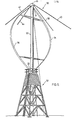
- 3arrieus vertical axis wind turbine 30 comprises vertical rotor shaft 32 ana rotor blades 34 ana 36 spaced from and secured to shaft 32, by connectors at 31 and 33.
- Four (4) guy wires shown as 38, 40, 42 and 44 are connected to, and support, wind turbine 30, through upper heaa assembly 46.
- the lower end of shaft 32 is secured for rotation in gear box assembly 50 (See Figures 8, 9, and 11) mounted in tower 52.
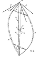
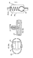
- rotor shaft 32 has been replaced by shaft 32 1 tapered from a broader central portion at 52 to reduced end portions at 54 and 56.
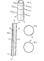
- Shaft 32 is made up of two tapered sections 58 and 60 (see also Figure 4) having angular flanges 61 extending radially from the sections at the broaaer ends 62 and 64 respectively for connecting the sections.
- Curved blades 34 and 36 are connected to shaft 32 proximate the ends in the same manner as in Figure 1.
- Figures 6 and 7 illustrate two cross-sections that shaft 32 1 may take.
- the circular cross-section shown in Figure 6 is preferred to the octagonal cross-section shown in Figure 7.
- Shaft 32 1 is preferred to shaft 32 in the construction of Darrieus vertical axis wind turbine 30. This is because constant diameter shaft 32 creates aerodynamic interference with eacn of the rotor blades 34 and 36 as each passes behind the rotor with respect to wind direction, reducing the efficiency of the rotor. The reason is the cumulative effect of the Von Karman vortex generation - The Von Karman vortex generation caused by the rotor shaft in the windstream is a function of shaft diameter. Since the diameter of the shaft 32 is constant, the frequency of the Von Karman vortices generated along the length of shaft 32 is constant, the vortices reinforce one another. The use of tapered shaft 32 1 tapering from a broader central portion to narrower ends produces a series of independent variable frequency vortices which are less disruptive to the performance of the blades passing in the "shadow" of the column.
- Figure 3 illustrates schematically the independent variable frequency vortices producea in the shadow of shaft 32 1 .
- tapered sections 58 and 60 connectea to form shaft 32 1.
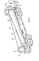
- tapered shaft 32 By producing tapered shaft 32 in two . sections, they may be shipped as shown in Figures 4 and 5. Particularly, highway regulations, regulate the maximum width of a vehicle and its capacity to carry oversized structures of large diameter. Where the load is oversized, special permits and/or a police escort are required. Because the diameter of large constant diameter rotors in excess of 120 feet is about 5', it is not ordinarily possible to ship the rotor in two sections loaded on one truck side by side. However, because the diameter of the section 58 and 60 taper from 5' to narrower 2' end portions, the sections may be shipped side by side as shown in Figure 5.
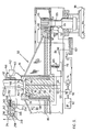
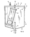
- gear box assembly 50 is shown, incorporating a hydraulic suspension system for supporting rotor shaft 32 or 32 (for simplifying description, rotor shaft 32 has been used) and bull gear 70 for rotation, and, for tensioning and supporting guy wires 38, 40, 42, and 44, under a constant tension whether or not the bull gear and rotor are operational.
- bull gear 70 has circular opening 72 at the top thereof surrounded by annular spherical bearing surface 74 for supporting the bottom surface 76 of shaft 32 proximate its radially outer bottom edge, shaft 32 seats in opening 32 on bearing surface 74 as shown.
- Bull gear 70 comprises (a) central hub 78 overlying end 80 of stationary shaft 82(of lesser diameter than hub 78), shaft 82 being secured to base 84 above which bull gear 70 will rotate (b) bottom plate 86 secured to hub 78, (c) gear ring 88 secured to the periphery of bottom plate 86 and (d) triangular stiffening webs 90 secured between plates 86 and hub 78.
- Base 84 supports brake pads 92 proximate the periphery of plate 26 for seating on brake pads 92 when Darrieus vertical axis wind turbine is not operational.
- end surface 80 of shaft 82 is either spaced from the inner end of hub 78 or in contact with it.
- Hydrodynamic bearings (not shown) are secured between the inner side wall of hub 78 and the outer side surface of vertical shaft 32 for sealing the space created between the end 80 of shaft 82, inner end wall of hub 94 ana the bottom surface 72 of rotor shaft 32 when bull gear 70 is raised relative to shaft 82.
- Hub 78 and rotor shaft 32 are free to rise with respect to shaft 82 limited by guy wire reaction and the hydraulic fluid permitted to enter space 102 between the shaft, hub and rotor, to support the hub and rotor as described herein.
- Bull gear 70 meshes with pinion gear 96 coupled to generator 98 for driving generator 98.
- Annular dam wall 100 sits on base 84 and separates the interior space under gear 70 from generator 98 and the remainder of equipment (not shown).
- Hub 70 and rotor shaft 32 are hydraulically supported with respect to stationary shaft 82 by hydraulic fluid fed into the space 102 created between the bottom surface 76 of rotor shaft 32, inner end 94, and end surface 80, as bull gear 70 and rotor 32 are elevated by fluid fed into space 102 from passageway 104 fed from reservoir 107 by hydraulic circuitry shown schematically in Figure 9.
- hydraulic fluid is fed into space 102 from reservoir 107 through passageway 104 by pump 110 operated by electric motor 112.
- Pump 114 operated on a common axis as pump 110 by motor 112 pumps fluid through passageway 116 to lubricate the gear/pinion mesh. Fluid passing down from the lubrication of the gear 88/pinion 96 mesh is collected through passageways 118 and 120 by returns 122 and 124.
- Fluid is normally drained from space 102 by outlet port 106 (of the same dimensions as passageway 104 ) througn drain passageway 108 in hubs 78 and returned to the reservoir 107 when bull gear 70 is elevated a predetermined distance above stationary shaft 82 exposing outlet port 106 to space 102. Therefore, gear 70 and rotor 32 cannot be elevated more than a predetermined distance because the feeding of hydraulic fluid into space 102 is maintained at a flow rate not to exceed the flow rate draining fluid through port 106 for return to reservoir 107.
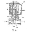
- valve 126--electrically operated two way direct-pilot-operated valve shown in cross-section in Figure 10-is normally closed and opens only upon electrical failure to the Darrieus vertical axis wind turbine 30.
- valve 126 is electrically powered to normally repel magnetic movable core 128 from stationary core 130 so long as electrically connected to a power source, compressing spring 132 of spring loaded sealing disc 134 to seal port 136 by stainless steel seat 138 .
- overspeed safety device 142 and associated components come into play.
- device 142 and associated components including passageway 144, leading from space 102 in rotor shaft 132 through branched portion 146 to device 142 are shown.
- Device 142 is secured by support bracket 145 to rotor 32 to rotate therewith, and is enclosed by housing 150 made up of reservoir 152 (See Figure 16) and weighted closure 154.
- Oil return and hold down pipe 156 extends upwardly through the bottom 158 of reservoir 152 and is releasably secured to top 154 by threaded bolt 160 secured into threaded end of pipe 156.
- Washer 163 compressingly seals the opening in top 154 through which bolt 160 extends and gasket 164 is positioned between top 154 and the top of continuous wall 166 of reservoir 152 to seal the space in housing 150 against leakage between the reservoir 152 and top 154.
- Pipe 156 has been notched at 162 to permit oil to orain from reservoir 152 to the sump (oil reservoir) 107.
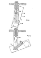
- Oil inlet 146 is secured to metal tube 168 passing through top 154 (See Figure 17) sealed by washer 155 and is closed by ball valve 170 supported on arm 172 to urge ball 170 to close tube 168 as shown 4n Figure 17.
- Arm 172 is in turn supported in pivotable upper valve lever arm 174 laterally pivotable in channel 180 of lower valve lever arm 182 with respect to arm 182.
- Channel 180 extends radially from rotor 32.
- Lower lever arm 182 is fixedly secured to rotatable shaft 184 (See Figure 20) passing therethrough to rotate therewith radially away from rotor shaft 32 from the position shown in Figure 17.
- Shaft 184 is fixed for rotation in support 186 secured to top 154 .
- Shaft 184 is in turn fixed to hollow square tubing 188 comprising elongated rectangular walls 190, 192, 194 and 196 so that when tubing 188 rotates, shaft 184, and arm 182 all rotate together away from the rotor shaft 32.
- Stop bolts 198 and 200 are secured across the center of the open ends of tubing 188 for stopping metal ball 202 from passing through the ends.
- Plate 204 (See Figures 18 and 21) is positioned on the inside surface of wall 192 proximate bolt 190.
- Tube 188 is secured to shaft 184 at an angle of to the vertical when ball valve 170 closes the opening 206 of inlet 168 sloping upwardly and radially outwardly from rotor shaft 32 (looking from the bottom of tubing 188) to provide radially upwardly anglea ramp 208 on the inside surface of wall 192.
- the resultant (R) approaches a position normal (N) to the plate until at the predetermined angular velocity, the resultant (R) passes the normal (N) exerting a clockwise moment about the center of gravity on sphere 202 causing sphere 202 to roll up ramp 208 altering the center of gravity of tubing 188, causing tubing 188 to rotate radially away from rotor shaft 32 on shaft 184 rotating shaft 184 and arm 182 thus opening inlet 168 (See Figure 9) permitting fluid in space 102 to drain through outlet 162, through passageway 156 to reservoir 107, causing bull gear 70 to settle on brake pads 92 stopping rotor 32 and bull gear 70.
- fluid fed through passageway 144 from space 102 normally passes through passageway 212 past Pressure Regulating Valve 214, check valve 216 and hydraulic damper 218 in passageway 212.
- upper head assembly 46 includes a shaft 220 secured to the top of rotor shaft 32 of lesser diameter than shaft 32 having passageway 222 passing therethrough in communication with passageway 212 and annular dam wall 223 surrounding shaft 220 spaced therefrom.
- Head 224 seats over shaft 220 and comprises annular wall 226, top 228 and downwardly opening annular endless channel 230 in wall 226 to accommodate dam wall 223.
- Annular seals 232 are positioned between dam wall 223 and annular channel wall 234 closest shaft 220 to seal a space between head 224 and 220.
- Hydrodynamic bearings 235 are secured between the inner surface of wall 226 and outer surface of shaft 220 for sealing the space created between the end of shaft 220 and the inner surface of top 228.
- Four triangular weos 236 extend from head 224 and secure guy wires 38, 40, 42 and 44 thereto.
- Drain 238 drains fluid from controlled bearing leakage past hydrodynamic bearings 235 from the space between seals 232 and hydrodynamic bearings 235.
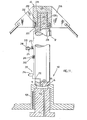
- upper head assembly 46 i comprises housing 300 secured to the top of shaft 32, housing 300 comprising base 301, annular wall 302 upstanding therefrom surrounding wall 303 and passageway 304 connecting passageway 212 and well 3 03.
- housing 300 comprising base 301, annular wall 302 upstanding therefrom surrounding wall 303 and passageway 304 connecting passageway 212 and well 3 03.
- shaft 305 Mounted and sealed by annular seals 306 within well 303 for vertical displacement relative to housing 303 and seals 306 is shaft 305.
- Fluid fed through passageways 212 and 304 against the bottom 307 of shaft 305 elevates shaft 305.
- Holes through top 308 of shaft 305 are used to secure the guy wires 38, 40, 42 and 44.
- Hydrodynamic bearings are also secured between the shaft 305 and inner wall of the housing 303.
- Drain 310 drains fluid from controlled bearing leakage past the hydrodynamic bearings from well 303.
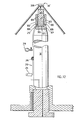
- Fluid pumped up passageway 144 entering passageway 212 and fed to head assembly 46 or 46 1 elevates head 224 relative to shaft 220 or shaft 305 from housing 300 respectively, thereby tensioning guy wires 38, 40, 42, and 44 .
- valve 214 To ensure guy tension is maintained relatively constant, direct acting pressure reducing valve 214(See Figure 9) has been inserted into passageway 212 and permits only enough oil to flow therethrough to maintain fluid pressure in the head assembly at the desired pressure.
- valve 214 comprises housing 240, spool 242, inlet port 244, outlet port 246, pressure sensing passage 248, compression spring 250, adjustment screw 252 extending through housing 240 and bleed passage 254.
- Valve 214 is held normally open by the force exerted by spring 250 (set by set screw 252) against spool 242. As the pressure in outlet port 246 increases (sensed by passage 248) the pressure of the fluid in passage 248 on the face 256 of spool 242 compresses spring 250 when the pressure exceeds the force of the spring, moving spool 242 to close outlet port 244. When valve 214 closes comoletely, a small quantity of fluid drains through passageway 258 to bleed passageway 254 to reservoir 107 (not shown) preventing reduced pressure from increasing because of valve leakage.
- Fluid passing valve 214 passes upwardly through one-way check valve 216 comprising housing 260 holding ball 262 at the bottom under compression by compression spring 264, under greater pressure than the pressure exerted by compression spring 264 tending to seat ball 262, through passageway 222 to raise head 224 or shaft 305 a predetermined amount as limited by the guys, tensioning the guys and maintaining the tension in the guys.
- one way check valve 216 precludes fluid from returning past valve 216 by closing under the compression force of spring 264 thereby maintaining the pressure in head assembly 210 and the guy tension in guy wires 38, 40 , 42 and 44.
- the "floating" of head 46 supplies damping to the entire rotor-gear box assembly.
- hydraulic damper 218 comprising air hydraulic accumulator 270 with hyaraulic restrictor 272 is provided.
- Figure 15 illustrates the tensioning of the guys employing head assembly 46 or 46'.
Landscapes
- Engineering & Computer Science (AREA)
- Life Sciences & Earth Sciences (AREA)
- Sustainable Development (AREA)
- Sustainable Energy (AREA)
- Chemical & Material Sciences (AREA)
- Combustion & Propulsion (AREA)
- Mechanical Engineering (AREA)
- General Engineering & Computer Science (AREA)
- Magnetic Bearings And Hydrostatic Bearings (AREA)
- Wind Motors (AREA)
Applications Claiming Priority (1)
| Application Number | Priority Date | Filing Date | Title |
|---|---|---|---|
| CA392524 | 1981-12-17 |
Publications (2)
| Publication Number | Publication Date |
|---|---|
| EP0082584A2 true EP0082584A2 (de) | 1983-06-29 |
| EP0082584A3 EP0082584A3 (de) | 1984-10-24 |
Family
ID=4121636
Family Applications (1)
| Application Number | Title | Priority Date | Filing Date |
|---|---|---|---|
| EP82302720A Withdrawn EP0082584A3 (de) | 1981-12-17 | 1982-05-26 | Windradwelle und deren Montage |
Country Status (2)
| Country | Link |
|---|---|
| EP (1) | EP0082584A3 (de) |
| AU (1) | AU8463682A (de) |
Family Cites Families (1)
| Publication number | Priority date | Publication date | Assignee | Title |
|---|---|---|---|---|
| NL7514750A (nl) * | 1975-12-18 | 1977-06-21 | Stichting Reactor Centrum | Windmoleninstallatie voor het opwekken van energie. |
-
1982
- 1982-05-26 EP EP82302720A patent/EP0082584A3/de not_active Withdrawn
- 1982-06-07 AU AU84636/82A patent/AU8463682A/en not_active Abandoned
Also Published As
| Publication number | Publication date |
|---|---|
| EP0082584A3 (de) | 1984-10-24 |
| AU8463682A (en) | 1983-06-23 |
Similar Documents
| Publication | Publication Date | Title |
|---|---|---|
| US4575311A (en) | Gear box assembly-upper head assembly | |
| US4664596A (en) | Vertical axis wind turbine and components therefor | |
| JP4351064B2 (ja) | 結合渦垂直軸風力タービン | |
| US4449053A (en) | Vertical axis wind turbine | |
| US4514145A (en) | Gear box assembly | |
| US4297075A (en) | Automatic storm protection control for wind energy system | |
| US4316096A (en) | Wind power generator and control therefore | |
| US5360290A (en) | Underground drainage facility, vertical-shaft multi-stage adjustable vane pump, and method of running drainage pump | |
| US4613282A (en) | Gear connection and brake assembly | |
| US20040076518A1 (en) | Tilt stabilized / ballast controlled wind turbine | |
| US4822239A (en) | Vertical axis windmill | |
| US4274807A (en) | Speed control system for a windmill | |
| US4659284A (en) | Wind turbines, improved gear box assemblies, and a braking system adaptable for use with such wind turbines and improved gear box assembly | |
| EP3353419B1 (de) | Schwimmende windenergiegewinnungsvorrichtung mit bremsanordnung und verfahren zur steuerung einer drehzahl der vorrichtung | |
| EP0082584A2 (de) | Windradwelle und deren Montage | |
| CA1252052A (en) | Rotor shaft (elliptical) | |
| CA1220390A (en) | Overspeed device | |
| CA1233122A (en) | Hydraulic suspension system | |
| CA1233123A (en) | Upper head assembly | |
| EP0775823A2 (de) | Von einer Windturbine angetriebene Wärme- oder Pumpvorrichtungen | |
| KR20120051973A (ko) | 풍력식 압축기 | |
| US4587435A (en) | Turbine | |
| GB2107794A (en) | Automatic storm protection control for wind energy system | |
| CA1241215A (en) | Gear connection and brake assembly | |
| JP2005083207A (ja) | ダリウス式風力発電装置 |
Legal Events
| Date | Code | Title | Description |
|---|---|---|---|
| PUAI | Public reference made under article 153(3) epc to a published international application that has entered the european phase |
Free format text: ORIGINAL CODE: 0009012 |
|
| AK | Designated contracting states |
Designated state(s): AT BE CH DE FR GB IT LI LU NL SE |
|
| PUAL | Search report despatched |
Free format text: ORIGINAL CODE: 0009013 |
|
| AK | Designated contracting states |
Designated state(s): AT BE CH DE FR GB IT LI LU NL SE |
|
| 17P | Request for examination filed |
Effective date: 19850424 |
|
| STAA | Information on the status of an ep patent application or granted ep patent |
Free format text: STATUS: THE APPLICATION IS DEEMED TO BE WITHDRAWN |
|
| 18D | Application deemed to be withdrawn |
Effective date: 19851231 |
|
| RIN1 | Information on inventor provided before grant (corrected) |
Inventor name: WOOD, CHARLES FRANCIS |