EP0082526A2 - Dispositif de mémoire à bulles magnétiques - Google Patents
Dispositif de mémoire à bulles magnétiques Download PDFInfo
- Publication number
- EP0082526A2 EP0082526A2 EP82111839A EP82111839A EP0082526A2 EP 0082526 A2 EP0082526 A2 EP 0082526A2 EP 82111839 A EP82111839 A EP 82111839A EP 82111839 A EP82111839 A EP 82111839A EP 0082526 A2 EP0082526 A2 EP 0082526A2
- Authority
- EP
- European Patent Office
- Prior art keywords
- ion
- bubble
- magnetic
- propagation path
- implanted region
- Prior art date
- Legal status (The legal status is an assumption and is not a legal conclusion. Google has not performed a legal analysis and makes no representation as to the accuracy of the status listed.)
- Ceased
Links
Images

Classifications
-
- G—PHYSICS
- G11—INFORMATION STORAGE
- G11C—STATIC STORES
- G11C19/00—Digital stores in which the information is moved stepwise, e.g. shift registers
- G11C19/02—Digital stores in which the information is moved stepwise, e.g. shift registers using magnetic elements
- G11C19/08—Digital stores in which the information is moved stepwise, e.g. shift registers using magnetic elements using thin films in plane structure
- G11C19/0875—Organisation of a plurality of magnetic shift registers
- G11C19/0883—Means for switching magnetic domains from one path into another path, i.e. transfer switches, swap gates or decoders
- G11C19/0891—Means for switching magnetic domains from one path into another path, i.e. transfer switches, swap gates or decoders using hybrid structure, e.g. ion doped layers
-
- G—PHYSICS
- G11—INFORMATION STORAGE
- G11C—STATIC STORES
- G11C19/00—Digital stores in which the information is moved stepwise, e.g. shift registers
- G11C19/02—Digital stores in which the information is moved stepwise, e.g. shift registers using magnetic elements
- G11C19/08—Digital stores in which the information is moved stepwise, e.g. shift registers using magnetic elements using thin films in plane structure
- G11C19/0875—Organisation of a plurality of magnetic shift registers
- G11C19/0883—Means for switching magnetic domains from one path into another path, i.e. transfer switches, swap gates or decoders
Definitions
- the present invention relates to a memory device for storing information in the form of bubbles of cylindrical magnetic domain, so-called magnetic bubbles, and more particularly, to a magnetic bubble memory device using a bubble propagation path formed by ion implantation and a bubble propagation path formed of magnetically soft elements in combination.
- ions such as He are implanted in accordance with a predetermined pattern on the surface of a bubble supporting layer, in which a magnetic bubble is held and propagated, so as to form a region in which magnetization is directed in the plane of the bubble supporting layer thereby to form a bubble propagation path.
- This propagation path (will be termed "ion-implantation propagation path" hereafter) is formed in a pattern without a gap, facilitating lithographical processes, and is advantageous for fabricating a device of high packaging density.
- the device needs to have functional portions for generating, replicating and detecting a magnetic bubble and controlling the propagation of the bubble, in addition to the storage loop formed by the propagation path.
- the ion-implantation propagation path there have not been achieved a replicater for making a replica of data on a propagation path and a swap gate for controlling data exchange between two propagation paths with satisfactory operational stability.
- soft-magnetic element propagation path an alignment of magnetically soft elements such as permalloy (will be hereafter termed "soft-magnetic element propagation path")
- soft-magnetic element propagation path although there have been realized replicaters and swap gates which operate stably, but it is disadvantageous for fabricating a device of high packaging density due to a certain gap width between patterns beyond which the gap can not be narrowed.
- a copending U.S. Patent Application, serial No. 375,344, Sugita et al. filed on May 5, 1982 discloses a compound magnetic bubble memory device which realizes high packing density and also stable operation.
- this compound magnetic bubble memory device the great part of storage loops (minor loops) are formed of an ion-implantation propagation path, and a read line for reading out data from the minor loops, a write line for writing data onto the minor loops, and a switch or replicater for connecting the read/write lines to the minor loops are formed of magnetically soft elements.
- One object of the present invention is to improve the marginal propagating performance of a soft-magnetic element propagation path in a compound magnetic bubble memory device.
- Another object of the invention is to provide a magnetic bubble memory device which presents a sufficient detection output.
- the present invention features that a magnetic bubble supporting layer beneath the soft-magnetic element propagation path and in the neighborhood thereof is given a condition of ion implantation which is different from the condition of ion implantation for forming the ion-implantation propagation path. More particularly, a portion for forming a soft-magnetic element pattern is provided with a thinner ion implantation layer, or the distortion in the plane of the layer caused by ion implantation is relieved, or both the measures are taken.
- the ion-implanted layer 2 is a magnetic layer with its magnetization directed in the plane of the layer, and therefore the magnetic flux from the soft-magnetic propagation path 5 is weakened by the ion-implanted layer 2, resulting in a weakened bubble driving force.
- the leakage flux from a magnetic bubble is also weakened and the output of a detector which senses the leakage flux from the magnetic bubble is reduced.
- Different thicknesses of the ion-implanted layer for the ion-implantation propagation path and the soft-magnetic element propagation path can be achieved by different conditions of ion implantation such as different acceleration voltages.
- the degree of distortion can be varied by varying the density of ion implantation or by selective heat treatment by means of such as laser-annealing following the ion implantation under the same condition.
- a write major line 11 and greater part of minor loops 9 were formed of an ion-implantation propagation path and the remaining part of the minor loops 9 and a read major line 7 were formed of permalloy propagation path.
- the permalloy propagation path is shown by the solid line, while the ion-implantation propagation path is shown by the dashed line.
- the ion-implantation propagation path is formed by the H 2 + implantation of 2x10 16 ions/ cm 2 at an acceleration voltage of 35 keV and by the H 2 + implantation of 4x10 16 ions/cm 2 at an acceleration voltage of 60 keV.
- the thickness of the ion-implanted 0 layer in this case was 3000 A approximately. Hatched region 12, i.e., portions above the detector 6, the read major line 7 and the minor loops 9, was simply processed by the Ne + implantation of 1x10 14 ions/cm 2 at an acceleration voltage of 50 keV for preventing the generation of a hard bubble. The thickness of the ion-implanted 0 layer in this case was 600 A approximately.
- a transfer gate 14 was used, which is identical to that disclosed in IEEE Transaction on Magnetics, Vol. MAG-17, No. 1, pp. 1134-1141.
- Various types of replicater can be used for replicater 8, and in this embodiment, a block replicater disclosed in IEEE Transcation on Magnetics, Vol. MAG-12, No. 6, pp. 614-617 was used.
- This type of device poses a problem on the bubble propagation characteristics in the boundary between the ion-implanted portion for creating the ion-implantation propagation path and the portion without such ion implantation.
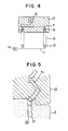
- Fig. 5 is an enlarged plan view showing the boundary portion.
- Region 2 is ion-implanted to form an ion-implanted path 21, and region 12 is processed by ion implantation for preventing the generation of a hard bubble.
- the latter ion implantation does not need to be limited to the region 12, but may be carried out for the entire surface of the device.
- a magnetic bubble propagated on the ion-implanted path 21 is attracted by a magnetic pole created on a permalloy element 51, then transferred along the outer edge of the element toward the top of the figure.
- the boundary between the ion-implanted region 2 and the ion-implanted region 12 is located midway on the permalloy element 51.
- the permalloy element 51 was made to have a length several times the pitch of the ion-implantation propagation path 21.
- the device was operated in the revolving magnetic field at a frequency of 100 kHz, and a marginal bias magnetic field of 8% relative to the total operating magnetic field was obtained. A large detection output of 1 mV/ 1 mA was also achieved.
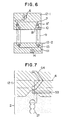
- Fig. 6 shows another embodiment of the present invention.
- a magnetic bubble generator 14, a write line ll.and a part of minor loops 9 connected to the write line 11 by swap gates 13 are formed of the soft-magnetic element propagation path, made of permalloy elements.
- the ion-implantation propagation path shown by the dashed line in the figure was processed by the Ne + implantation of 1x10 14 ions/cm 2 at 50 keV, the Ne + implantation of 2x10 14 ions/cm 2 at 180 keV, and the H 2 + implantation of 3x10 16 ions/cm 2 at 100 keV, and the remaining portions (regions 12-1 and 12-2 in Fig.
- Such deeper ion implantation is effective for preventing the generation of a hard bubble, and also effective for sharing the bias magnetic field range, where a magnetic bubble exists in the bubble supporting layer, for the portion of the ion-implantation propagation path and the portion of the permalloy propagation path.
- a magnetic bubble can exist in the bubble supporting layer only when the bias magnetic field applied perpendicularly to the layer falls in a certain range, and particularly, a critical field Ho which provides the upper limit of the range varies depending on the depth of ion implantation and the amount of ion implantation. It is undesirable for a magnetic bubble device to have portions with significantly different value of this.
- the regions 12-1 and 12-2 were also ion-implantated to a depth and in a density which are in a range where the propagation margin for the soft-magnetic propagation path and the detection output by the bubble detector are not adversely affected.
- the upper end of the minor loop 9 is connected to the permalloy propagation path using a transfer gate 10.
- a hairpin-shaped conductor 4 is disposed so as to connect the ion-implantation propagation path and the soft-magnetic element propagation path made of permalloy elements 53 and 54.
- a magnetic bubble is propagated on the ion-implantation propagation path 21 constituting a minor loop, and only when replication is needed, the magnetic bubble is transferred to the permalloy propagation path by supplying a current to the conductor 4.
- a replicater 8' used in this embodiment is different from the replicater 8 in Fig. 4, but is a passive replicater, and it divides each coming magnetic bubble into two without using any special pulse current.
- One of the divided magnetic bubble goes through a read line 7 to a bubble detector 6, and the other one returns through a bypass 81 to the minor loop 9 formed of the ion-implantation propagation path.
- the number of bits of the bypass 81 has been adjusted so that a magnetic bubble coming through the replicater returns to the original bit address in the minor loop.
- the above-mentioned passive replicater is disclosed in IEEE Transaction on Magnetics, Vol. MAG-16, p. 858, (1980), by L. Tao et al.
- the ion-implantation propagation path is connected directly to the soft-magnetic element propagation path on the side of the write line, and the arrangement is identical to that shown in Fig. 5 on this aspect.
- modification may be made such that the write line 11 is connected to the minor loop 9 formed of the soft-magnetic element propagation path using a transfer gate made of a hairpin-shaped conductor.
Landscapes
- Thin Magnetic Films (AREA)
Applications Claiming Priority (2)
| Application Number | Priority Date | Filing Date | Title |
|---|---|---|---|
| JP203723/81 | 1981-12-18 | ||
| JP56203723A JPS58108085A (ja) | 1981-12-18 | 1981-12-18 | 磁気バブル素子 |
Publications (2)
| Publication Number | Publication Date |
|---|---|
| EP0082526A2 true EP0082526A2 (fr) | 1983-06-29 |
| EP0082526A3 EP0082526A3 (fr) | 1986-05-14 |
Family
ID=16478776
Family Applications (1)
| Application Number | Title | Priority Date | Filing Date |
|---|---|---|---|
| EP82111839A Ceased EP0082526A3 (fr) | 1981-12-18 | 1982-12-20 | Dispositif de mémoire à bulles magnétiques |
Country Status (3)
| Country | Link |
|---|---|
| US (1) | US4601013A (fr) |
| EP (1) | EP0082526A3 (fr) |
| JP (1) | JPS58108085A (fr) |
Cited By (5)
| Publication number | Priority date | Publication date | Assignee | Title |
|---|---|---|---|---|
| US4584668A (en) * | 1984-04-24 | 1986-04-22 | Hitachi, Ltd. | Magnetic bubble memory device |
| FR2587823A1 (fr) * | 1985-09-20 | 1987-03-27 | Hitachi Ltd | Dispositif de memoire a bulles magnetiques |
| FR2593957A1 (fr) * | 1986-02-05 | 1987-08-07 | Commissariat Energie Atomique | Memoire a bulles magnetiques en technologie hybride |
| FR2593956A1 (fr) * | 1986-02-05 | 1987-08-07 | Commissariat Energie Atomique | Memoire a bulles magnetiques en technologie hybride |
| EP0174144A3 (en) * | 1984-08-27 | 1988-03-16 | Hitachi, Ltd. | Process for preparing magnetic layer and magnetic head prepared using the same |
Families Citing this family (2)
| Publication number | Priority date | Publication date | Assignee | Title |
|---|---|---|---|---|
| JPS607682A (ja) * | 1983-06-27 | 1985-01-16 | Fujitsu Ltd | 磁気バブルメモリ素子 |
| JPS6070577A (ja) * | 1983-09-27 | 1985-04-22 | Fujitsu Ltd | 磁気バブルメモリ素子 |
Citations (3)
| Publication number | Priority date | Publication date | Assignee | Title |
|---|---|---|---|---|
| US4040019A (en) * | 1974-08-23 | 1977-08-02 | Texas Instruments Incorporated | Ion implanted magnetic bubble memory device having major and minor rows |
| EP0026518A1 (fr) * | 1979-09-28 | 1981-04-08 | Koninklijke Philips Electronics N.V. | Structure à domaines magnétiques en forme de bulles |
| DE3217533A1 (de) * | 1981-05-11 | 1982-12-09 | Hitachi, Ltd., Tokyo | Magnetblasenspeicher-bauelement |
Family Cites Families (7)
| Publication number | Priority date | Publication date | Assignee | Title |
|---|---|---|---|---|
| US4171389A (en) * | 1975-03-13 | 1979-10-16 | Bell Telephone Laboratories, Incorporated | Process for suppressing hard bubbles in magnetic bubble devices |
| JPS5846793B2 (ja) * | 1976-12-24 | 1983-10-18 | 富士通株式会社 | 磁気バブル素子 |
| JPS5528518A (en) * | 1978-08-17 | 1980-02-29 | Fujitsu Ltd | Control method of magnetic bubble steady existence magnetic field for magnetic bubble memory element |
| JPS5538601A (en) * | 1978-08-30 | 1980-03-18 | Fujitsu Ltd | Magnetic bubble element |
| JPS56111178A (en) * | 1980-02-07 | 1981-09-02 | Fujitsu Ltd | Magnetic bubble element |
| JPS6059669B2 (ja) * | 1980-08-25 | 1985-12-26 | 富士通株式会社 | 高密度バブルメモリ素子 |
| JPS58125289A (ja) * | 1982-01-22 | 1983-07-26 | Hitachi Ltd | 磁気バブル素子 |
-
1981
- 1981-12-18 JP JP56203723A patent/JPS58108085A/ja active Pending
-
1982
- 1982-12-20 EP EP82111839A patent/EP0082526A3/fr not_active Ceased
-
1985
- 1985-02-27 US US06/706,182 patent/US4601013A/en not_active Expired - Lifetime
Patent Citations (3)
| Publication number | Priority date | Publication date | Assignee | Title |
|---|---|---|---|---|
| US4040019A (en) * | 1974-08-23 | 1977-08-02 | Texas Instruments Incorporated | Ion implanted magnetic bubble memory device having major and minor rows |
| EP0026518A1 (fr) * | 1979-09-28 | 1981-04-08 | Koninklijke Philips Electronics N.V. | Structure à domaines magnétiques en forme de bulles |
| DE3217533A1 (de) * | 1981-05-11 | 1982-12-09 | Hitachi, Ltd., Tokyo | Magnetblasenspeicher-bauelement |
Non-Patent Citations (2)
| Title |
|---|
| IBM TECHNICAL DISCLOSURE BULLETIN, vol. 20, no. 10, March 1978, pages 4207-4208, New York, US; Y.S. LIN: "Ion-implanted bubble domain devices" * |
| IEEE TRANSACTIONS ON MAGNETICS, vol. MAG-13, no. 6, November 1977, pages 1744-1764, IEEE, New York, US; Y.S LIN et al.: "Contiguous-disk bubble domain devices" * |
Cited By (11)
| Publication number | Priority date | Publication date | Assignee | Title |
|---|---|---|---|---|
| US4584668A (en) * | 1984-04-24 | 1986-04-22 | Hitachi, Ltd. | Magnetic bubble memory device |
| EP0174144A3 (en) * | 1984-08-27 | 1988-03-16 | Hitachi, Ltd. | Process for preparing magnetic layer and magnetic head prepared using the same |
| US4772976A (en) * | 1984-08-27 | 1988-09-20 | Hitachi, Ltd. | Process for preparing magnetic layer and magnetic head prepared using the same |
| US4894098A (en) * | 1984-08-27 | 1990-01-16 | Hitachi, Ltd. | Process for preparing magnetic layer and magnetic head prepared using the same |
| FR2587823A1 (fr) * | 1985-09-20 | 1987-03-27 | Hitachi Ltd | Dispositif de memoire a bulles magnetiques |
| FR2593957A1 (fr) * | 1986-02-05 | 1987-08-07 | Commissariat Energie Atomique | Memoire a bulles magnetiques en technologie hybride |
| FR2593956A1 (fr) * | 1986-02-05 | 1987-08-07 | Commissariat Energie Atomique | Memoire a bulles magnetiques en technologie hybride |
| EP0237374A1 (fr) * | 1986-02-05 | 1987-09-16 | Commissariat A L'energie Atomique | Mémoire à bulles magnétique en technologie hybride |
| EP0238370A1 (fr) * | 1986-02-05 | 1987-09-23 | Commissariat A L'energie Atomique | Mémoire à bulles magnétiques en technologie hybride |
| US4773054A (en) * | 1986-02-05 | 1988-09-20 | Commissariat A L'energie Atomique | Magnetic bubble memory with a hybrid junction |
| US4791605A (en) * | 1986-02-05 | 1988-12-13 | Commissariat A L'energie Atomique | Hybrid junction for a magnetic bubble memory |
Also Published As
| Publication number | Publication date |
|---|---|
| JPS58108085A (ja) | 1983-06-28 |
| US4601013A (en) | 1986-07-15 |
| EP0082526A3 (fr) | 1986-05-14 |
Similar Documents
| Publication | Publication Date | Title |
|---|---|---|
| US3967002A (en) | Method for making high density magnetic bubble domain system | |
| US4086572A (en) | Magnetic bubble domain replicator | |
| US4164029A (en) | Apparatus for high density bubble storage | |
| US4601013A (en) | Magnetic bubble memory device | |
| EP0011137A1 (fr) | Fabrication d'un chip à domaines magnétiques à bulles ayant des marges de propagation améliorées | |
| US4528645A (en) | Magnetic bubble memory device | |
| US4104422A (en) | Method of fabricating magnetic bubble circuits | |
| US3832701A (en) | Transfer circuit for single wall domains | |
| EP0081215B1 (fr) | Mémoire à bulles magnétiques | |
| US3996573A (en) | Bubble propagation circuits and formation thereof | |
| US4525808A (en) | Hybrid magnetic bubble memory device | |
| US4164026A (en) | Contiguous element field access bubble lattice file | |
| US4434476A (en) | Magnetic bubble memory device and method for operating the same | |
| JPS6059669B2 (ja) | 高密度バブルメモリ素子 | |
| US4744052A (en) | Hybrid magnetic bubble memory device | |
| GB1582471A (en) | Magnetic memories for the storage of data | |
| US4516222A (en) | Laminated magnetic bubble device | |
| US4494216A (en) | Magnetic bubble memory device | |
| US4507755A (en) | Magnetic bubble memory device | |
| US4584668A (en) | Magnetic bubble memory device | |
| US4559617A (en) | Magnetic bubble memory device | |
| US4578775A (en) | Magnetic bubble memory device | |
| US4357683A (en) | Magnetic bubble memory with ion-implanted layer | |
| JP2763917B2 (ja) | ブロッホラインメモリデバイス | |
| US4547865A (en) | Magnetic bubble replicator |
Legal Events
| Date | Code | Title | Description |
|---|---|---|---|
| PUAI | Public reference made under article 153(3) epc to a published international application that has entered the european phase |
Free format text: ORIGINAL CODE: 0009012 |
|
| AK | Designated contracting states |
Designated state(s): DE FR GB |
|
| PUAL | Search report despatched |
Free format text: ORIGINAL CODE: 0009013 |
|
| AK | Designated contracting states |
Kind code of ref document: A3 Designated state(s): DE FR GB |
|
| 17P | Request for examination filed |
Effective date: 19860909 |
|
| 17Q | First examination report despatched |
Effective date: 19871204 |
|
| STAA | Information on the status of an ep patent application or granted ep patent |
Free format text: STATUS: THE APPLICATION HAS BEEN REFUSED |
|
| 18R | Application refused |
Effective date: 19891002 |
|
| REG | Reference to a national code |
Ref country code: DK Ref legal event code: CTFG Free format text: DKCTFGCA 1996 00018, 960909, EXPIRES: 20110808 |
|
| RIN1 | Information on inventor provided before grant (corrected) |
Inventor name: SUZUKI, RYO Inventor name: KODAMA, NAOKI Inventor name: SUGITA, YUTAKA Inventor name: TAKEUCHI, TERUAKI Inventor name: TAKESHITA, MASATOSHI |