EP0082152B1 - Coupling device for the coupling up or uncoupling preferably of a drive roller for a roller conveyor - Google Patents
Coupling device for the coupling up or uncoupling preferably of a drive roller for a roller conveyor Download PDFInfo
- Publication number
- EP0082152B1 EP0082152B1 EP19820900673 EP82900673A EP0082152B1 EP 0082152 B1 EP0082152 B1 EP 0082152B1 EP 19820900673 EP19820900673 EP 19820900673 EP 82900673 A EP82900673 A EP 82900673A EP 0082152 B1 EP0082152 B1 EP 0082152B1
- Authority
- EP
- European Patent Office
- Prior art keywords
- coupling
- control
- arms
- control ring
- drive roller
- Prior art date
- Legal status (The legal status is an assumption and is not a legal conclusion. Google has not performed a legal analysis and makes no representation as to the accuracy of the status listed.)
- Expired
Links
Images


Classifications
-
- B—PERFORMING OPERATIONS; TRANSPORTING
- B65—CONVEYING; PACKING; STORING; HANDLING THIN OR FILAMENTARY MATERIAL
- B65G—TRANSPORT OR STORAGE DEVICES, e.g. CONVEYORS FOR LOADING OR TIPPING, SHOP CONVEYOR SYSTEMS OR PNEUMATIC TUBE CONVEYORS
- B65G13/00—Roller-ways
- B65G13/02—Roller-ways having driven rollers
- B65G13/06—Roller driving means
- B65G13/073—Roller driving means comprising free-wheel gearing
-
- B—PERFORMING OPERATIONS; TRANSPORTING
- B65—CONVEYING; PACKING; STORING; HANDLING THIN OR FILAMENTARY MATERIAL
- B65G—TRANSPORT OR STORAGE DEVICES, e.g. CONVEYORS FOR LOADING OR TIPPING, SHOP CONVEYOR SYSTEMS OR PNEUMATIC TUBE CONVEYORS
- B65G47/00—Article or material-handling devices associated with conveyors; Methods employing such devices
- B65G47/22—Devices influencing the relative position or the attitude of articles during transit by conveyors
- B65G47/26—Devices influencing the relative position or the attitude of articles during transit by conveyors arranging the articles, e.g. varying spacing between individual articles
- B65G47/261—Accumulating articles
-
- F—MECHANICAL ENGINEERING; LIGHTING; HEATING; WEAPONS; BLASTING
- F16—ENGINEERING ELEMENTS AND UNITS; GENERAL MEASURES FOR PRODUCING AND MAINTAINING EFFECTIVE FUNCTIONING OF MACHINES OR INSTALLATIONS; THERMAL INSULATION IN GENERAL
- F16D—COUPLINGS FOR TRANSMITTING ROTATION; CLUTCHES; BRAKES
- F16D11/00—Clutches in which the members have interengaging parts
- F16D11/02—Clutches in which the members have interengaging parts disengaged by a contact of a part mounted on the clutch with a stationarily-mounted member
- F16D11/06—Clutches in which the members have interengaging parts disengaged by a contact of a part mounted on the clutch with a stationarily-mounted member with clutching members movable otherwise than only axially, e.g. rotatable keys
Definitions
- the present invention relates to a coupling device for the coupling up or uncoupling of a drive roller mounted for rotation about a pivot shaft, for example for a roller conveyor, and comprising two coupling members which are rotatable coaxially with the pivot shaft of the drive roller and which are adapted to be changed over, by means of a control member between a coupled together state in which they are held against rotation in relation to one another and a state in which they are uncoupled from one another and in which the coupling members are permitted to rotate in relation to one another, one of the coupling members being connected to the drive roller which is held against rotation in relation thereto and the other coupling member being connected to a rotatable drive device, said one coupling member comprising at least one coupling surface and said other coupling member comprising at least three coupling portions each of which is pivotable about its own pivot shaft substantially parallel to the pivot shaft of the drive roller and at least three coupling members which can be changed over, by means of the coupling arms, between a release position and a coupling position.
- a coupling device having pivotable coupling arms which are adjustable between a coupling position and releasing position.
- the known device has an outer annular element which is a coupling member which is to be coupled into and out of respectively engagement with the central drive shaft.
- a bushing is displaced for each arm axially in order to come out of engagement with cam surfaces of the outer coupling member.
- the actuation of the known device is consequently relatively complicated and makes the known device utilizable for merely very special applications.
- This reference does not mention any solution to the difficult problem to establish an actuation movement from a control member which is not rotatable and positioned outside of the coupling and to the rotatable members which are to be adjusted.
- the object of the present invention is to provide a simple and operationally reliable coupling device which can be produced at relatively low cost.
- the other coupling member includes a circular control ring which is situated radially outside the coupling arms and is displaceable substantially radially, said control ring having an inner contact surface, by means of which the control ring is arranged to cooperate with a control portion of the coupling arms and with an outer contact surface, by means of which the control ring is arranged to cooperate with the control member, the coupling arms being spring-loaded into a coupling position in which the control ring is held centered about the pivot shaft of the drive roller and the coupling members are in engagement with the coupling surface or surfaces of the one coupling member and can be changed over into a release position to change over the coupling members from a coupling position to a release position by pressing the control member against the outer contact surface of the control ring, causing substantially radial displacement of the control ring to an eccentric position relatively to said pivot shaft and a pressing of the control ring with its inner contact surface against the control portions of the coupling arms for said pivoting movement of
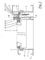
- FIG. 1 shows a partially broken view of a coupling device according to the invention in a second embodiment mounted on a drive roller for a roller conveyor
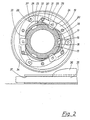
- Figs. 2 and 3 are sections through the coupling device of Fig. 1 in the coupled position and uncoupled position respectively, on the line 11-11 in Fig. 1
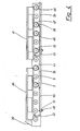
- Fig. 4 is a partially broken view of a part of a roller conveyor with drive rollers provided with coupling devices according to the invention
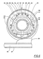
- Fig. 5 and 6 show sectional views through the coupling device in a second embodiment in the coupled and uncoupled position respectively
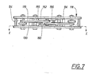
- Fig. 7 is an end view of the coupling device according to the second embodiment.
- the coupling device 1 is particularly suitable for coupling in and uncoupling drive rollers 2, one of which is shown in Fig. 1 rotatably mounted about a pivot shaft 3 which is secured in a frame 4 and forms, together with this and a further number of drive rollers and non-driven rollers so called supporting rollers 5, a roller conveyor, one end of which is shown in Fig. 4.
- the frame consists mainly of two longitudinal beams 6, 7 which in the example shown, have C-shaped cross-section.
- the two beams 6, 7 are carried by a chassis 8 which is included in the frame 4 and which is only indicated by a line in Fig. 1.
- the drive roller 2 is rotatably mounted about its pivot shaft 3 by means of a ball bearing 9 at one end and, in the example shown, three ball bearings 10, 11, 12 at its other end, by means of which the coupling device 1 is also rotatably mounted about the pivot shaft 3 of the drive roller.
- the coupling device 1 is provided with a first coupling member 13 which is rotatably mounted about the pivot shaft 3 by means of the bearings 11, 12 and which carries a pinion 14 mounted on this coupling member for rotation therewith but not in relation thereto.
- the pinion 14 is adapted to be in communication, via a drive chain not shown, with a drive device, not shown, for example an electric motor together with corresponding pinions on a number of other drive rollers in the roller conveyor.
- the bearing 10 is mounted between the first coupling member and the drive roller 2 and, in the uncoupled position of the coupling device 1, permits relative rotational movement between the first coupling member and the drive roller, as will be described in more detail below.
- the first coupling member 13 comprises a plurality of radially directed engagement portions 15, of which there are six in the example shown and which comprise two engagement edges 16, 17 facing one another.
- the pivot shaft 3 and the bearing 11 have been omitted for the sake of clarity.
- the coupling device is further composed of a second coupling member 18 which is connected to the drive roller 2 for rotation therewith but not in relation thereto and comprises a plurality of coupling hook elements 19, of which there are six in the example shown, and which are each pivotally mounted about their own pivot shafts 20 in a holder which, in the example shown, consists of two annular disc elements 21, 22 which are parallel with one another and which are rigidly mounted for example by welding to the cylindrical body 23 of the drive roller (see Fig. 1).
- Each of the coupling hook elements 19 is constructed in the form of a swinging lever with a hooking portion 24 and a control portion 25.
- the coupling hook elements 19 face one another in pairs and are apportioned to one another both in the hooking portion 24 and in the control portion 25 and connected to one another by means of a pin 26, 27 which is mounted in each end of each coupling nuok element and which is rigidly mounted in one of two portions associated with one another and is inserted in a somewhat oblong opening 28, 29 which forms a guide for the associated pin.
- every other coupling hook element 19 may be duplicated and so comprise double elements which are mutually rigidly connected with spacing by means of the pins 26, 27. In this case, the simple elements are inserted in the gap between the double elements.
- the coupling hook element 19 is spring loaded by means of the spring element 30, which in the example shown, is mounted on three of the hook elements 19 and more precisely round the associated pivot shaft 20.
- each spring element 30 is secured by its one end 31 in a bore in the associated hook element 29 and is supported, at its other end 32 against the cylindrical body of the drive roller. This comprises three openings 33 through which the hook elements can extend with their hooking portions 24.
- the spring element tends to pivot the coupling hook element 19 so that its hooking portion 24 is pressed radially inwards and tends to come into engagement with the engagement portions 15 on the first coupling member 13 while the opposite end of the coupling hook element, that is to say the control portion 25, tends to be pressed radially outwards.
- control ring 34 which is carried by the coupling hook element 19 and which rests with its inside against the control portion 25 of the coupling hook element and is guided sideways between the two disc elements 21, 22 of the holder. Nevertheless, there is a certain play between the control ring 34 and the disc element so that the control ring is able to be displaced in a plane perpendicular to the pivot shaft 3 and substantially radially in the coupling position of the coupling device. In addition, the ring can slide, that is to say rotate, in relation to the hook element. In Fig. 2, the control ring 34 is shown situated coaxially with the pivot shaft 3, the coupling hook element being in engagement with. the engagement portion 15 of the first coupling member. The control ring 34 is thus held in this position under the influence of the spring element 30 via the coupling hook element 19.
- the coupling device 1 also includes a control arm 35 which comprises a control portion 36.
- the control arm 35 is adapted to be displaced along a guide 37 between a lower position as shown in Fig. 2 in which the control portion 36 does not act on the control ring 34 so that the coupling device is in the coupling position, and an activated position as shown in Fig. 3 in which the control arm 35 is displaced along the guide 37 parallel to the direction of the tangent to the control ring 34, as a result of which the control arm with its control end 36 causes a substantially radially displacement of the control ring 34 into a position which is eccentric in relation to the pivot shaft 3.
- the control ring 34 is braked during the changeover of the coupling device to the uncoupled position first by its friction against the control end 36, while the coupling hook element is able to slide with its control portion 25 against the inside of the control ring until the coupling hook element is swung over into the release position and the engagement position ceases, whereupon all the elements in the second coupling member cease to rotate and so also does the drive roller, while the first coupling member 11 can continue its rotation.
- the coupling device is changes over from the uncoupled position to the coupling position by pulling the control arm 35 down.
- the control ring 34 is relieved of the pressure from the control end 36 whereupon the control ring and hence the coupling hook elements resume their position shown in Fig. 2 under the influence of the spring elements 30.
- the hooking portions 24 are pressed radially inwards towards the first coupling member 13 and slide against its peripheral surface 38 and as soon as the coupling member 13 which is constantly in rotation so long as the roller conveyor is in operation, is in such a torsional position that its engagement portions 15 come immediately in front of the hook portions 24 of the hook elements 19, these are pressed into the engagement portions and assume the coupling position, entraining the second coupling member and hence the drive roller 2.
- engagement is obtained regardless of the direction of rotation of the first coupling member 13.
- Fig. 4 shows one end of a roller conveyor which comprises a stop element 39 up to which articles are conveyed for unloading from the roller conveyor. These articles are represented by loading pallets 40, 41 in the example shown.
- a detecting arm 42 for each group of drive rollers.
- the drive rollers in a first group are designated by 2, 44, 45 and 46, while a second group of drive rollers which can be coupled in and uncoupled comprise an equally great number, of which two drive rollers 47, 48 are shown.
- the articles are conveyed along the roller conveyor being driven forward by means of the drive rollers which, by being driven by means of an associated drive device, are caused to rotate and so to convey the loading pallets.
- the detecting arms 42, 43 project upwards between two rollers and are pivotally mounted in the frame of the roller conveyor about a shaft 49 and are loaded by means of a spring, not shown, so that they tend to assume a swung-upwards position projecting between two rollers.
- the detecting arm 42 Via an articulated arm 50, the detecting arm 42 is articulately connected to the control arm 35 which is common to each of the groups of drive rollers. Therefore, four control portions 36 are mounted on each control arm 35, one for each drive roller which can be coupled up and uncoupled in each group.
- the control portions 36 are so situated that they are in the activated position, uncoupling the coupling device, when the detecting arm 42 is in the pressed down position as shown in Fig. 4. This is brought about as a result of the fact that the articulated arm 50 is articulately connected to the control arm at a joint 51 which is a short distance away from the pivot pin 49 of the detecting arm, as a result of which leverage occurs which leads to a displacement movement of the control arm 35 so that the detecting portions 36 can be changed over between a lowered and an activated position.
- the control arms 35 and the associated control portion 36 are in the lowered position, in which case the coupling devices in each of the drive rollers is in a coupling position, meaning that the drive rollers are coupled in for driving and are so in driving connection with the drive device.
- the loading pallets can thus be conveyed along the roller conveyor.
- the drive rollers 2, 44, 45, 46 are changed over from the driving state when the coupling device in the coupling position to the uncoupled state in which these drive rollers stop.
- the corresponding group of drive rollers 47, 48 is changed over in a corresponding manner from the driving state to the uncoupled state, as a result of which these are stopped and the drive rollers are prevented from sliding against the loading pallet.
- the detecting arm 42 When the loading pallet 40 is removed from the roller conveyor the detecting arm 42 is raised under the action of its spring which means that the associated drive rollers 2, 44, 45, 46 are changed over to the driving state, as a result of which the loading pallet 41 is conveyed forwards to the end of the conveyor despite the fact that the detecting arm 43 is pressed down. After the load pallet 41 has passed the detecting arm 23, this is also raised so that the associated group of drive rollers can be changed over to the driving state and following load pallets can be conveyed forwards in a corresponding manner.
- the coupling device is not constructed in the form of a claw coupling with positive locking between the two coupling members but is of the friction coupling type with frictional engagement.
- This second form of embodiment is shown by way of example in Fig. 5 which shows the coupling in the coupling position, Fig. 6 shows the coupling in the release position and Fig. 7 which shows the coupling in a partially cut-away view from above.
- Figs. 5 and 6 are sections on the line V-V in Fig. 7.
- the first coupling member 113 that is to say the coupling member situated at the drive side in the example, comprises an axially symmetrical coupling surface 116 round the pivot shaft of the drive roller.
- coupling jaws 152 with friction linings 153 are coupled to the coupling arms 119 and are adapted to be pressed against the coupling surface 116 of the coupling member 113 in the coupling position of the device.
- the coupling arms 119 are coupled together and are articulately connected to one another by means of pivot pins 127.
- Said pins 127 form a number of pivoting points between the coupling arms which together form a closed endless unit.
- the coupling jaws 152 are situated in connection with every second pivoting point between the coupling arms.
- three coupling jaws are provided which are articulately connected to each coupling arm by means of two pivot pins 155, 156, one pivot pin for each coupling arm.
- the coupling jaws 152 are orientated to one end 154 of the coupling arms, the opposite end 125 of which forming control portions supporting the control ring 134.
- the coupling jaws 152 are provided with lateral slits 129 for engagement with the pivoting pins 155, 156, said pins 155, 156 are positioned between the pivot axis 120 of each coupling arm 119 and the pivot pin 127 at each coupling jaw 152.
- the coupling arms 119 are articulately connected to the holder 118 by means of a pivot shaft 120 which extends between the two annular disc elements 121 of the holder, one of which is removed by the section.
- the control portion 125 of the coupling arms is adapted to cooperate with the inside of the control ring 134 which in the coupling position of the device is situated substantially symmetrically in relation to the axis of rotation of the drive roller and of the device.
- each coupling jaw 152 comprises a groove 160 which the pivot pin 155 bridges and extends through a bore in the coupling arm 119. Every coupling jaw 152 has a recess 157 engaging the pivot pin 127 for lateral positioning of the coupling jaw. At every pivoting point between the coupling arms 119 the openings 129 for the pivoting pins 127 are oblong in order to allow the necessary movements.
- the control arm 135 In the coupling position of the coupling device, as in the first exampIe, the control arm 135 is in a lowered position with its control portion 136 which is thus not in contact with the control ring 134. In this position the coupling jaws 152 are held pressed under the influence of springs 130 (as in the previous example) with their friction linings 153 against the coupling surface 116, as a result of which the two coupling members 121, 122 are coupled together without mutual turning and the drive roller can be entrained by the drive device.
- the control arm 135 When the coupling device is to be changed over into the release position for example to uncouple the drive roller from the drive device, the control arm 135 is displaced along its guide 137, the control portion 136 being pressed substantially tangentially or parallel to the tangent against the control ring 134. This is then displaced substantially radially whereupon the control ring is braked by friction against the control portion 136 and slides in relation to the other parts of the coupling device which rotate together with the drive roller in the coupling position.
- the coupling arms 119 When the control ring is displaced, the coupling arms 119 are pressed in by pressing of the inside of the control ring against the radially outer ends of the coupling arms, that is to say their control portions 125.
- control arms are swung into the position shown in Fig. 6 and form coherent arcuate-shaped portions in each pair.
- the opposite ends 154 of the control arms swing out which means that the coupling jaws 152 by means of the pivot pins 155 are lifted radially outwards from bearing against the coupling surfaces 116 against the action of the springs 130, whereupon the coupling device is released and the one coupling member and hence also the drive roller stops, while the other coupling member to which the coupling surface 116 belongs, is permitted to rotate.
- the device When the coupling device is to be changed over from the release to the coupling position, the device acts in the same manner in principle but with the opposite movements.
- the control arm 135 When the control arm 135 is displaced so that the control portion 136 is again brought into the position shown in Fig. 5, the control ring 134 is enabled to assume its symmetrical position.
- the coupling arms 119 are able to swing out when their control portions 125 by the action of their springs 130 leading to the fact that the coupling jaws 152 are again pressed inwards against the coupling surface 116 by means of the pivot pins, whereupon the drive roller is again entrained by the rotating coupling member and accompanies its rotational- movement.
- a more gentle transition between the various coupling positions is naturally obtained by the friction of the coupling jaws 152, slipping against the coupling surface 116 occurring at the beginning.
- a slight clearance may be an advantage between the control ring 134 and the control portions 125 of any one of the coupling arms 119 to ensure the pressing of the coupling jaws 152 into the coupling position, not least in view of the changes in position which are caused by wear of the friction lining of the coupling jaws.
- the coupling arms comprise, at one end, coupling members which can be. changed over between a coupling position and a release position by displacement of the coupling member. These are exposed to spring forces which tend to bring the coupling members into the coupling position.
- the actual coupling arms are formed as a coupling member at one end while in the second case the coupling member consists of a separate element which is connected to the coupling arm.
- the coupling device according to the second example can be used in precisely the same manner as the device according to the first example, so that the application as shown in Fig. 4 can comprise coupling devices according to one example or the other.
- the coupling hook elements may be formed in various ways and may, for example, be constructed in the form of a one-armed lever with its pivotal axis situated at one end of the element.
- the activation of the control ring 34 can be effected in another manner for example by means of an element directed more radially rather than tangentially.
- the coupling device is intended primarily for the drive rollers of roller conveyors, other applications are conceivable where couplings of the present type, that is to say claw couplings, occur.
Abstract
Description
- The present invention relates to a coupling device for the coupling up or uncoupling of a drive roller mounted for rotation about a pivot shaft, for example for a roller conveyor, and comprising two coupling members which are rotatable coaxially with the pivot shaft of the drive roller and which are adapted to be changed over, by means of a control member between a coupled together state in which they are held against rotation in relation to one another and a state in which they are uncoupled from one another and in which the coupling members are permitted to rotate in relation to one another, one of the coupling members being connected to the drive roller which is held against rotation in relation thereto and the other coupling member being connected to a rotatable drive device, said one coupling member comprising at least one coupling surface and said other coupling member comprising at least three coupling portions each of which is pivotable about its own pivot shaft substantially parallel to the pivot shaft of the drive roller and at least three coupling members which can be changed over, by means of the coupling arms, between a release position and a coupling position.
- From Derwent abstract A 5564B/03, SU 594 365 a coupling device is prior known having pivotable coupling arms which are adjustable between a coupling position and releasing position. The known device has an outer annular element which is a coupling member which is to be coupled into and out of respectively engagement with the central drive shaft. For adjustment to releasing position a bushing is displaced for each arm axially in order to come out of engagement with cam surfaces of the outer coupling member. The actuation of the known device is consequently relatively complicated and makes the known device utilizable for merely very special applications. This reference does not mention any solution to the difficult problem to establish an actuation movement from a control member which is not rotatable and positioned outside of the coupling and to the rotatable members which are to be adjusted.
- The object of the present invention is to provide a simple and operationally reliable coupling device which can be produced at relatively low cost.
- Said object is achieved by means of a device which is characterized in that the other coupling member includes a circular control ring which is situated radially outside the coupling arms and is displaceable substantially radially, said control ring having an inner contact surface, by means of which the control ring is arranged to cooperate with a control portion of the coupling arms and with an outer contact surface, by means of which the control ring is arranged to cooperate with the control member, the coupling arms being spring-loaded into a coupling position in which the control ring is held centered about the pivot shaft of the drive roller and the coupling members are in engagement with the coupling surface or surfaces of the one coupling member and can be changed over into a release position to change over the coupling members from a coupling position to a release position by pressing the control member against the outer contact surface of the control ring, causing substantially radial displacement of the control ring to an eccentric position relatively to said pivot shaft and a pressing of the control ring with its inner contact surface against the control portions of the coupling arms for said pivoting movement of the control arms.
- The invention will be described in more detail below with reference to the accompanying drawings in which Fig. 1 shows a partially broken view of a coupling device according to the invention in a second embodiment mounted on a drive roller for a roller conveyor, Figs. 2 and 3 are sections through the coupling device of Fig. 1 in the coupled position and uncoupled position respectively, on the line 11-11 in Fig. 1, while Fig. 4 is a partially broken view of a part of a roller conveyor with drive rollers provided with coupling devices according to the invention. Fig. 5 and 6 show sectional views through the coupling device in a second embodiment in the coupled and uncoupled position respectively, whereas Fig. 7 is an end view of the coupling device according to the second embodiment.
- The
coupling device 1 according to the invention is particularly suitable for coupling in anduncoupling drive rollers 2, one of which is shown in Fig. 1 rotatably mounted about a pivot shaft 3 which is secured in aframe 4 and forms, together with this and a further number of drive rollers and non-driven rollers so called supportingrollers 5, a roller conveyor, one end of which is shown in Fig. 4. The frame consists mainly of twolongitudinal beams beams frame 4 and which is only indicated by a line in Fig. 1. - The
drive roller 2 is rotatably mounted about its pivot shaft 3 by means of a ball bearing 9 at one end and, in the example shown, threeball bearings coupling device 1 is also rotatably mounted about the pivot shaft 3 of the drive roller. - The
coupling device 1 according to the invention is provided with afirst coupling member 13 which is rotatably mounted about the pivot shaft 3 by means of thebearings pinion 14 mounted on this coupling member for rotation therewith but not in relation thereto. Thepinion 14 is adapted to be in communication, via a drive chain not shown, with a drive device, not shown, for example an electric motor together with corresponding pinions on a number of other drive rollers in the roller conveyor. Thebearing 10 is mounted between the first coupling member and thedrive roller 2 and, in the uncoupled position of thecoupling device 1, permits relative rotational movement between the first coupling member and the drive roller, as will be described in more detail below. - As can be seen from Figs. 2 and 3, the
first coupling member 13 comprises a plurality of radially directedengagement portions 15, of which there are six in the example shown and which comprise twoengagement edges bearing 11 have been omitted for the sake of clarity. The coupling device is further composed of asecond coupling member 18 which is connected to thedrive roller 2 for rotation therewith but not in relation thereto and comprises a plurality ofcoupling hook elements 19, of which there are six in the example shown, and which are each pivotally mounted about theirown pivot shafts 20 in a holder which, in the example shown, consists of twoannular disc elements cylindrical body 23 of the drive roller (see Fig. 1). Each of thecoupling hook elements 19 is constructed in the form of a swinging lever with ahooking portion 24 and acontrol portion 25. Thecoupling hook elements 19 face one another in pairs and are apportioned to one another both in the hookingportion 24 and in thecontrol portion 25 and connected to one another by means of apin oblong opening coupling hook element 19 may be duplicated and so comprise double elements which are mutually rigidly connected with spacing by means of thepins coupling hook element 19 is spring loaded by means of thespring element 30, which in the example shown, is mounted on three of thehook elements 19 and more precisely round the associatedpivot shaft 20. In the example shown, eachspring element 30 is secured by its oneend 31 in a bore in the associatedhook element 29 and is supported, at itsother end 32 against the cylindrical body of the drive roller. This comprises threeopenings 33 through which the hook elements can extend with their hookingportions 24. The spring element tends to pivot thecoupling hook element 19 so that its hookingportion 24 is pressed radially inwards and tends to come into engagement with theengagement portions 15 on thefirst coupling member 13 while the opposite end of the coupling hook element, that is to say thecontrol portion 25, tends to be pressed radially outwards. - Included in the
second coupling member 18 is acontrol ring 34 which is carried by thecoupling hook element 19 and which rests with its inside against thecontrol portion 25 of the coupling hook element and is guided sideways between the twodisc elements control ring 34 and the disc element so that the control ring is able to be displaced in a plane perpendicular to the pivot shaft 3 and substantially radially in the coupling position of the coupling device. In addition, the ring can slide, that is to say rotate, in relation to the hook element. In Fig. 2, thecontrol ring 34 is shown situated coaxially with the pivot shaft 3, the coupling hook element being in engagement with. theengagement portion 15 of the first coupling member. Thecontrol ring 34 is thus held in this position under the influence of thespring element 30 via thecoupling hook element 19. - The
coupling device 1 also includes acontrol arm 35 which comprises acontrol portion 36. Thecontrol arm 35 is adapted to be displaced along aguide 37 between a lower position as shown in Fig. 2 in which thecontrol portion 36 does not act on thecontrol ring 34 so that the coupling device is in the coupling position, and an activated position as shown in Fig. 3 in which thecontrol arm 35 is displaced along theguide 37 parallel to the direction of the tangent to thecontrol ring 34, as a result of which the control arm with itscontrol end 36 causes a substantially radially displacement of thecontrol ring 34 into a position which is eccentric in relation to the pivot shaft 3. This means that thecoupling hook element 19, since itscontrol portion 25 is pressed radially inwards, is swung into the position shown in Fig. 3 against the action of thespring element 30. As thecontrol ring 34 is displaced radially, thehook elements 19 together assume more and more the shape of a circular ring. The circular shaped is formed completely in the uncoupled position shown in Fig. 3. This ring has a radius of curvature which is less than the radius of curvature of the control ring. While thecoupling device 1 is in the coupling position as shown in Fig. 2, the second coupling member, that is to say the outer portion of the coupling and hence the drive roller, is entrained which means that thecontrol ring 34 also rotates. As a result of the fact that its outside is completely circular and as a result of the fact that the control ring is suspended "floating" and is able to rotate in relation to thecoupling hook element 19, thecontrol ring 34 is braked during the changeover of the coupling device to the uncoupled position first by its friction against thecontrol end 36, while the coupling hook element is able to slide with itscontrol portion 25 against the inside of the control ring until the coupling hook element is swung over into the release position and the engagement position ceases, whereupon all the elements in the second coupling member cease to rotate and so also does the drive roller, while thefirst coupling member 11 can continue its rotation. - In the reverse manner, the coupling device is changes over from the uncoupled position to the coupling position by pulling the
control arm 35 down. In the course of this, thecontrol ring 34 is relieved of the pressure from thecontrol end 36 whereupon the control ring and hence the coupling hook elements resume their position shown in Fig. 2 under the influence of thespring elements 30. In the course of this, the hookingportions 24 are pressed radially inwards towards thefirst coupling member 13 and slide against itsperipheral surface 38 and as soon as thecoupling member 13 which is constantly in rotation so long as the roller conveyor is in operation, is in such a torsional position that itsengagement portions 15 come immediately in front of thehook portions 24 of thehook elements 19, these are pressed into the engagement portions and assume the coupling position, entraining the second coupling member and hence thedrive roller 2. As a result of the shape of the engagement portions and the doubly directed action of the hook portions as a result of the hook elements facing one another, engagement is obtained regardless of the direction of rotation of thefirst coupling member 13. - Fig. 4 shows one end of a roller conveyor which comprises a
stop element 39 up to which articles are conveyed for unloading from the roller conveyor. These articles are represented byloading pallets arm 42 for each group of drive rollers. In Fig. 4, the drive rollers in a first group are designated by 2, 44, 45 and 46, while a second group of drive rollers which can be coupled in and uncoupled comprise an equally great number, of which twodrive rollers - The articles are conveyed along the roller conveyor being driven forward by means of the drive rollers which, by being driven by means of an associated drive device, are caused to rotate and so to convey the loading pallets. In the absence of articles in the roller conveyor, the detecting
arms 42, 43 project upwards between two rollers and are pivotally mounted in the frame of the roller conveyor about ashaft 49 and are loaded by means of a spring, not shown, so that they tend to assume a swung-upwards position projecting between two rollers. Via an articulatedarm 50, the detectingarm 42 is articulately connected to thecontrol arm 35 which is common to each of the groups of drive rollers. Therefore, fourcontrol portions 36 are mounted on eachcontrol arm 35, one for each drive roller which can be coupled up and uncoupled in each group. Thecontrol portions 36 are so situated that they are in the activated position, uncoupling the coupling device, when the detectingarm 42 is in the pressed down position as shown in Fig. 4. This is brought about as a result of the fact that the articulatedarm 50 is articulately connected to the control arm at ajoint 51 which is a short distance away from thepivot pin 49 of the detecting arm, as a result of which leverage occurs which leads to a displacement movement of thecontrol arm 35 so that the detectingportions 36 can be changed over between a lowered and an activated position. - Thus, so long as no article holds the detecting
arms 42, 43 pressed down, thecontrol arms 35 and the associatedcontrol portion 36 are in the lowered position, in which case the coupling devices in each of the drive rollers is in a coupling position, meaning that the drive rollers are coupled in for driving and are so in driving connection with the drive device. The loading pallets can thus be conveyed along the roller conveyor. When there is no loading pallet at the end of the roller conveyor, a conveying of the loading pallets takes place even when they press down the first detecting arm 43 and so uncouple the associated group ofdrive rollers arm 42. This means that the loading pallets are driven forwards by means of the twodrive rollers other rollers arm 42 situated closest to the end of the conveyor. When theloading pallet 40 has reached the end of the conveyor and so been stopped by means of theend stop 39 and the detectingarm 42 has been pressed down, thedrive rollers loading pallet 41 has pressed down the detecting arm 43, the corresponding group ofdrive rollers loading pallet 40 is removed from the roller conveyor the detectingarm 42 is raised under the action of its spring which means that the associateddrive rollers loading pallet 41 is conveyed forwards to the end of the conveyor despite the fact that the detecting arm 43 is pressed down. After theload pallet 41 has passed the detectingarm 23, this is also raised so that the associated group of drive rollers can be changed over to the driving state and following load pallets can be conveyed forwards in a corresponding manner. - According to another form of embodiment, the coupling device is not constructed in the form of a claw coupling with positive locking between the two coupling members but is of the friction coupling type with frictional engagement. This second form of embodiment is shown by way of example in Fig. 5 which shows the coupling in the coupling position, Fig. 6 shows the coupling in the release position and Fig. 7 which shows the coupling in a partially cut-away view from above. Figs. 5 and 6 are sections on the line V-V in Fig. 7.
- In this form of embodiment, all the parts which correspond to parts in the form of embodiment shown in Figs. 2 and 3 are designated by corresponding numerals with the addition of the number 100. The friction coupling as shown in Figs. 5, 6 and 7 can be mounted in the
drive roller 2 as shown in Fig. 1 in the same manner as the claw coupling, but the construction of the coupling differs in certain parts. Thus thefirst coupling member 113, that is to say the coupling member situated at the drive side in the example, comprises an axiallysymmetrical coupling surface 116 round the pivot shaft of the drive roller. Furthermore, couplingjaws 152 withfriction linings 153 are coupled to thecoupling arms 119 and are adapted to be pressed against thecoupling surface 116 of thecoupling member 113 in the coupling position of the device. In this example also, the couplingarms 119 are coupled together and are articulately connected to one another by means of pivot pins 127. Said pins 127 form a number of pivoting points between the coupling arms which together form a closed endless unit. Thecoupling jaws 152 are situated in connection with every second pivoting point between the coupling arms. Thus, in the example shown, three coupling jaws are provided which are articulately connected to each coupling arm by means of twopivot pins coupling jaws 152 are orientated to oneend 154 of the coupling arms, theopposite end 125 of which forming control portions supporting thecontrol ring 134. Thecoupling jaws 152 are provided withlateral slits 129 for engagement with the pivoting pins 155, 156, saidpins pivot axis 120 of eachcoupling arm 119 and thepivot pin 127 at eachcoupling jaw 152. By analogy with the preceding example the couplingarms 119 are articulately connected to theholder 118 by means of apivot shaft 120 which extends between the twoannular disc elements 121 of the holder, one of which is removed by the section. Thecontrol portion 125 of the coupling arms is adapted to cooperate with the inside of thecontrol ring 134 which in the coupling position of the device is situated substantially symmetrically in relation to the axis of rotation of the drive roller and of the device. - As can be seen from Fig. 7, each
coupling jaw 152 comprises agroove 160 which thepivot pin 155 bridges and extends through a bore in thecoupling arm 119. Everycoupling jaw 152 has arecess 157 engaging thepivot pin 127 for lateral positioning of the coupling jaw. At every pivoting point between the couplingarms 119 theopenings 129 for the pivoting pins 127 are oblong in order to allow the necessary movements. - In the coupling position of the coupling device, as in the first exampIe, the
control arm 135 is in a lowered position with itscontrol portion 136 which is thus not in contact with thecontrol ring 134. In this position thecoupling jaws 152 are held pressed under the influence of springs 130 (as in the previous example) with theirfriction linings 153 against thecoupling surface 116, as a result of which the twocoupling members 121, 122 are coupled together without mutual turning and the drive roller can be entrained by the drive device. - When the coupling device is to be changed over into the release position for example to uncouple the drive roller from the drive device, the
control arm 135 is displaced along itsguide 137, thecontrol portion 136 being pressed substantially tangentially or parallel to the tangent against thecontrol ring 134. This is then displaced substantially radially whereupon the control ring is braked by friction against thecontrol portion 136 and slides in relation to the other parts of the coupling device which rotate together with the drive roller in the coupling position. When the control ring is displaced, the couplingarms 119 are pressed in by pressing of the inside of the control ring against the radially outer ends of the coupling arms, that is to say theircontrol portions 125. In the course of this, the control arms are swung into the position shown in Fig. 6 and form coherent arcuate-shaped portions in each pair. At the same time the opposite ends 154 of the control arms swing out which means that thecoupling jaws 152 by means of the pivot pins 155 are lifted radially outwards from bearing against the coupling surfaces 116 against the action of thesprings 130, whereupon the coupling device is released and the one coupling member and hence also the drive roller stops, while the other coupling member to which thecoupling surface 116 belongs, is permitted to rotate. - When the coupling device is to be changed over from the release to the coupling position, the device acts in the same manner in principle but with the opposite movements. When the
control arm 135 is displaced so that thecontrol portion 136 is again brought into the position shown in Fig. 5, thecontrol ring 134 is enabled to assume its symmetrical position. In this case, the couplingarms 119 are able to swing out when theircontrol portions 125 by the action of theirsprings 130 leading to the fact that thecoupling jaws 152 are again pressed inwards against thecoupling surface 116 by means of the pivot pins, whereupon the drive roller is again entrained by the rotating coupling member and accompanies its rotational- movement. - Through the friction coupling, a more gentle transition between the various coupling positions is naturally obtained by the friction of the
coupling jaws 152, slipping against thecoupling surface 116 occurring at the beginning. As indicated in the drawing a slight clearance may be an advantage between thecontrol ring 134 and thecontrol portions 125 of any one of the couplingarms 119 to ensure the pressing of thecoupling jaws 152 into the coupling position, not least in view of the changes in position which are caused by wear of the friction lining of the coupling jaws. - Thus common to both forms of embodiment is the simple construction of the coupling with pivotable control arms which are surrounded by a control ring which is displaceable substantially radially in relation to the axis of rotation of the drive roller so as to change the coupling over between the coupling position and the release position as a result of the fact that. the coupling arms comprise, at one end, coupling members which can be. changed over between a coupling position and a release position by displacement of the coupling member. These are exposed to spring forces which tend to bring the coupling members into the coupling position. In the first example the actual coupling arms are formed as a coupling member at one end while in the second case the coupling member consists of a separate element which is connected to the coupling arm.
- The coupling device according to the second example can be used in precisely the same manner as the device according to the first example, so that the application as shown in Fig. 4 can comprise coupling devices according to one example or the other.
- The invention is not restricted to the example of embodiment described above and shown in the drawings but can be varied in a plurality of ways within the scope of the following claims. For example, the coupling hook elements may be formed in various ways and may, for example, be constructed in the form of a one-armed lever with its pivotal axis situated at one end of the element. The activation of the
control ring 34 can be effected in another manner for example by means of an element directed more radially rather than tangentially. Although the coupling device is intended primarily for the drive rollers of roller conveyors, other applications are conceivable where couplings of the present type, that is to say claw couplings, occur.
Claims (11)
Applications Claiming Priority (2)
| Application Number | Priority Date | Filing Date | Title |
|---|---|---|---|
| SE8101243 | 1981-02-26 | ||
| SE8101243A SE427020B (en) | 1981-02-26 | 1981-02-26 | CLUTCH DEVICE FOR CONNECTING OR DISCONNECTING BUSINESS A DRIVE ROLLER FOR ROLL TRANSPORTERS |
Publications (2)
| Publication Number | Publication Date |
|---|---|
| EP0082152A1 EP0082152A1 (en) | 1983-06-29 |
| EP0082152B1 true EP0082152B1 (en) | 1986-07-16 |
Family
ID=20343219
Family Applications (1)
| Application Number | Title | Priority Date | Filing Date |
|---|---|---|---|
| EP19820900673 Expired EP0082152B1 (en) | 1981-02-26 | 1982-02-24 | Coupling device for the coupling up or uncoupling preferably of a drive roller for a roller conveyor |
Country Status (6)
| Country | Link |
|---|---|
| EP (1) | EP0082152B1 (en) |
| CA (1) | CA1181022A (en) |
| DE (1) | DE3271975D1 (en) |
| DK (1) | DK150575C (en) |
| SE (1) | SE427020B (en) |
| WO (1) | WO1982002869A1 (en) |
Families Citing this family (5)
| Publication number | Priority date | Publication date | Assignee | Title |
|---|---|---|---|---|
| DE3540299C1 (en) * | 1985-11-13 | 1987-04-30 | Fredenhagen Kg | Drive arrangement for a conveying device |
| SE462483B (en) * | 1987-02-19 | 1990-07-02 | Lars Sirefelt | actuator |
| DK161591C (en) * | 1989-03-01 | 1991-12-30 | Univeyor As | accumulation conveyor |
| ITUD20020130A1 (en) | 2002-06-10 | 2003-12-10 | Edoardo Facchini | TRANSMISSION DEVICE |
| CN111824695A (en) * | 2019-04-17 | 2020-10-27 | 梅特勒-托利多安全线有限公司 | Drive roller assembly for a conveyor system and conveyor system comprising same |
Family Cites Families (5)
| Publication number | Priority date | Publication date | Assignee | Title |
|---|---|---|---|---|
| US1118456A (en) * | 1912-10-01 | 1914-11-24 | Joseph A Wilkin | Clutch device. |
| DE909428C (en) * | 1952-04-26 | 1954-04-15 | Eickhoff Geb | Slipping clutch for conveyor belt drives |
| DK103230A (en) * | 1959-12-02 | |||
| SU594365A2 (en) * | 1976-11-15 | 1978-02-25 | Предприятие П/Я А-7114 | Clutch |
| GB1584432A (en) * | 1977-04-29 | 1981-02-11 | Fenner Co Ltd J H | Pulley assemblies |
-
1981
- 1981-02-26 SE SE8101243A patent/SE427020B/en not_active IP Right Cessation
-
1982
- 1982-02-24 WO PCT/SE1982/000054 patent/WO1982002869A1/en active IP Right Grant
- 1982-02-24 DE DE8282900673T patent/DE3271975D1/en not_active Expired
- 1982-02-24 EP EP19820900673 patent/EP0082152B1/en not_active Expired
- 1982-02-25 CA CA000397109A patent/CA1181022A/en not_active Expired
- 1982-10-26 DK DK473582A patent/DK150575C/en not_active IP Right Cessation
Also Published As
| Publication number | Publication date |
|---|---|
| SE8101243L (en) | 1982-11-05 |
| DE3271975D1 (en) | 1986-08-21 |
| WO1982002869A1 (en) | 1982-09-02 |
| DK150575B (en) | 1987-03-30 |
| DK473582A (en) | 1982-10-26 |
| CA1181022A (en) | 1985-01-15 |
| DK150575C (en) | 1987-10-19 |
| SE427020B (en) | 1983-02-28 |
| EP0082152A1 (en) | 1983-06-29 |
Similar Documents
| Publication | Publication Date | Title |
|---|---|---|
| CA1242467A (en) | Feeding means for feeding a material web in a packaging machine | |
| US5014864A (en) | Conveyor system | |
| EP0082152B1 (en) | Coupling device for the coupling up or uncoupling preferably of a drive roller for a roller conveyor | |
| JPH0416371B2 (en) | ||
| US3858707A (en) | Conveyor system | |
| US5087163A (en) | Stitching press for book blocks | |
| RU2529092C2 (en) | Coupling unit with connection elements built-in in friction rolling surface, coupler and conveyor | |
| US6378440B1 (en) | Overhead conveyor rotator system | |
| US5467860A (en) | Chain for accumulating conveyor | |
| JP2525596B2 (en) | A device that winds or unwinds the flexible sheet material that is continuously fed. | |
| CN1025312C (en) | Roller conveyor | |
| CN113751348B (en) | Swing arm device for logistics sorting | |
| US6843358B1 (en) | Rotatable transfer track device | |
| SU1288130A1 (en) | Belt conveyer intermediate drive | |
| EP0461164A1 (en) | An accumulation conveyor. | |
| CZ185995A3 (en) | Press with gripping rails | |
| US4355581A (en) | Truck driving apparatus | |
| KR200183960Y1 (en) | Automatic centering return roller having a break pad | |
| CN220149197U (en) | Filling machine and bottle clamping device thereof | |
| CN217577656U (en) | Material receiving and discharging device | |
| JPH0120332Y2 (en) | ||
| CN212686643U (en) | Continuous type lane device | |
| US3896922A (en) | Proofing box plant | |
| SU1247318A2 (en) | Overhead pushing conveyer for conveying automobiles | |
| SU1046148A1 (en) | Apparatus for automatic release of railway cars |
Legal Events
| Date | Code | Title | Description |
|---|---|---|---|
| PUAI | Public reference made under article 153(3) epc to a published international application that has entered the european phase |
Free format text: ORIGINAL CODE: 0009012 |
|
| 17P | Request for examination filed |
Effective date: 19830324 |
|
| AK | Designated contracting states |
Designated state(s): BE DE FR GB NL |
|
| GRAA | (expected) grant |
Free format text: ORIGINAL CODE: 0009210 |
|
| AK | Designated contracting states |
Kind code of ref document: B1 Designated state(s): BE DE FR GB NL |
|
| REF | Corresponds to: |
Ref document number: 3271975 Country of ref document: DE Date of ref document: 19860821 |
|
| ET | Fr: translation filed | ||
| PLBE | No opposition filed within time limit |
Free format text: ORIGINAL CODE: 0009261 |
|
| STAA | Information on the status of an ep patent application or granted ep patent |
Free format text: STATUS: NO OPPOSITION FILED WITHIN TIME LIMIT |
|
| 26N | No opposition filed | ||
| PGFP | Annual fee paid to national office [announced via postgrant information from national office to epo] |
Ref country code: GB Payment date: 19910225 Year of fee payment: 10 |
|
| PGFP | Annual fee paid to national office [announced via postgrant information from national office to epo] |
Ref country code: FR Payment date: 19910227 Year of fee payment: 10 |
|
| PGFP | Annual fee paid to national office [announced via postgrant information from national office to epo] |
Ref country code: NL Payment date: 19910228 Year of fee payment: 10 |
|
| PGFP | Annual fee paid to national office [announced via postgrant information from national office to epo] |
Ref country code: BE Payment date: 19910305 Year of fee payment: 10 |
|
| PG25 | Lapsed in a contracting state [announced via postgrant information from national office to epo] |
Ref country code: GB Effective date: 19920224 |
|
| PG25 | Lapsed in a contracting state [announced via postgrant information from national office to epo] |
Ref country code: BE Effective date: 19920228 |
|
| PGFP | Annual fee paid to national office [announced via postgrant information from national office to epo] |
Ref country code: DE Payment date: 19920321 Year of fee payment: 11 |
|
| BERE | Be: lapsed |
Owner name: WASSBERG KURT Effective date: 19920228 Owner name: SIREFELT LARS Effective date: 19920228 |
|
| PG25 | Lapsed in a contracting state [announced via postgrant information from national office to epo] |
Ref country code: NL Effective date: 19920901 |
|
| NLV4 | Nl: lapsed or anulled due to non-payment of the annual fee | ||
| GBPC | Gb: european patent ceased through non-payment of renewal fee | ||
| PG25 | Lapsed in a contracting state [announced via postgrant information from national office to epo] |
Ref country code: FR Effective date: 19921030 |
|
| REG | Reference to a national code |
Ref country code: FR Ref legal event code: ST |
|
| PG25 | Lapsed in a contracting state [announced via postgrant information from national office to epo] |
Ref country code: DE Effective date: 19931103 |