EP0082004B1 - Verfahren zur Herstellung eines Versandmittels mit beigefügtem Antwortumschlag - Google Patents
Verfahren zur Herstellung eines Versandmittels mit beigefügtem Antwortumschlag Download PDFInfo
- Publication number
- EP0082004B1 EP0082004B1 EP82306636A EP82306636A EP0082004B1 EP 0082004 B1 EP0082004 B1 EP 0082004B1 EP 82306636 A EP82306636 A EP 82306636A EP 82306636 A EP82306636 A EP 82306636A EP 0082004 B1 EP0082004 B1 EP 0082004B1
- Authority
- EP
- European Patent Office
- Prior art keywords
- sheet
- envelope
- outer envelope
- enclosure
- sheets
- Prior art date
- Legal status (The legal status is an assumption and is not a legal conclusion. Google has not performed a legal analysis and makes no representation as to the accuracy of the status listed.)
- Expired
Links
- 238000000034 method Methods 0.000 title claims description 41
- 230000004044 response Effects 0.000 claims description 57
- 239000002131 composite material Substances 0.000 claims description 55
- 238000004519 manufacturing process Methods 0.000 claims description 12
- 238000009966 trimming Methods 0.000 claims description 9
- 230000013011 mating Effects 0.000 claims description 5
- 239000000853 adhesive Substances 0.000 description 13
- 230000001070 adhesive effect Effects 0.000 description 13
- 238000005520 cutting process Methods 0.000 description 10
- 239000011324 bead Substances 0.000 description 9
- 230000009172 bursting Effects 0.000 description 6
- 238000005304 joining Methods 0.000 description 4
- 230000002349 favourable effect Effects 0.000 description 3
- 238000002788 crimping Methods 0.000 description 2
- 230000000737 periodic effect Effects 0.000 description 2
- 238000000926 separation method Methods 0.000 description 2
- 239000004831 Hot glue Substances 0.000 description 1
- 238000004026 adhesive bonding Methods 0.000 description 1
- 230000006872 improvement Effects 0.000 description 1
- 238000003780 insertion Methods 0.000 description 1
- 230000037431 insertion Effects 0.000 description 1
- 239000007788 liquid Substances 0.000 description 1
- 239000000463 material Substances 0.000 description 1
- 238000012015 optical character recognition Methods 0.000 description 1
- 230000008520 organization Effects 0.000 description 1
- 238000002360 preparation method Methods 0.000 description 1
- 230000008569 process Effects 0.000 description 1
- 238000003908 quality control method Methods 0.000 description 1
- 238000007789 sealing Methods 0.000 description 1
- 239000002699 waste material Substances 0.000 description 1
Images
Classifications
-
- B—PERFORMING OPERATIONS; TRANSPORTING
- B42—BOOKBINDING; ALBUMS; FILES; SPECIAL PRINTED MATTER
- B42D—BOOKS; BOOK COVERS; LOOSE LEAVES; PRINTED MATTER CHARACTERISED BY IDENTIFICATION OR SECURITY FEATURES; PRINTED MATTER OF SPECIAL FORMAT OR STYLE NOT OTHERWISE PROVIDED FOR; DEVICES FOR USE THEREWITH AND NOT OTHERWISE PROVIDED FOR; MOVABLE-STRIP WRITING OR READING APPARATUS
- B42D5/00—Sheets united without binding to form pads or blocks
- B42D5/02—Form sets
- B42D5/023—Continuous form sets
- B42D5/025—Mailer assemblies
- B42D5/026—Mailer assemblies with return letter or return card
-
- B—PERFORMING OPERATIONS; TRANSPORTING
- B31—MAKING ARTICLES OF PAPER, CARDBOARD OR MATERIAL WORKED IN A MANNER ANALOGOUS TO PAPER; WORKING PAPER, CARDBOARD OR MATERIAL WORKED IN A MANNER ANALOGOUS TO PAPER
- B31B—MAKING CONTAINERS OF PAPER, CARDBOARD OR MATERIAL WORKED IN A MANNER ANALOGOUS TO PAPER
- B31B2150/00—Flexible containers made from sheets or blanks, e.g. from flattened tubes
-
- B—PERFORMING OPERATIONS; TRANSPORTING
- B31—MAKING ARTICLES OF PAPER, CARDBOARD OR MATERIAL WORKED IN A MANNER ANALOGOUS TO PAPER; WORKING PAPER, CARDBOARD OR MATERIAL WORKED IN A MANNER ANALOGOUS TO PAPER
- B31B—MAKING CONTAINERS OF PAPER, CARDBOARD OR MATERIAL WORKED IN A MANNER ANALOGOUS TO PAPER
- B31B2160/00—Shape of flexible containers
- B31B2160/10—Shape of flexible containers rectangular and flat, i.e. without structural provision for thickness of contents
-
- B—PERFORMING OPERATIONS; TRANSPORTING
- B31—MAKING ARTICLES OF PAPER, CARDBOARD OR MATERIAL WORKED IN A MANNER ANALOGOUS TO PAPER; WORKING PAPER, CARDBOARD OR MATERIAL WORKED IN A MANNER ANALOGOUS TO PAPER
- B31B—MAKING CONTAINERS OF PAPER, CARDBOARD OR MATERIAL WORKED IN A MANNER ANALOGOUS TO PAPER
- B31B2170/00—Construction of flexible containers
- B31B2170/20—Construction of flexible containers having multi-layered walls, e.g. laminated or lined
-
- Y—GENERAL TAGGING OF NEW TECHNOLOGICAL DEVELOPMENTS; GENERAL TAGGING OF CROSS-SECTIONAL TECHNOLOGIES SPANNING OVER SEVERAL SECTIONS OF THE IPC; TECHNICAL SUBJECTS COVERED BY FORMER USPC CROSS-REFERENCE ART COLLECTIONS [XRACs] AND DIGESTS
- Y10—TECHNICAL SUBJECTS COVERED BY FORMER USPC
- Y10S—TECHNICAL SUBJECTS COVERED BY FORMER USPC CROSS-REFERENCE ART COLLECTIONS [XRACs] AND DIGESTS
- Y10S493/00—Manufacturing container or tube from paper; or other manufacturing from a sheet or web
- Y10S493/916—Pliable container
- Y10S493/917—Envelope
- Y10S493/921—Envelope having integrally formed insert
Definitions
- This invention relates to the manufacture of articles suitable for mailing comprising an outer envelope containing at least one pre-printed enclosure and a pre-formed return envelope, one or more of which can be personalized.
- the method described herein is particularly suited for commercial production of articles such as advertisements, solicitations, billings and the like, in which the printed contents are for the most part the same, and tens of thousands, or even millions of articles must be mailed. Such mailings often include a return envelope to encourage a favorable and prompt reply.
- a mailed article is personalized when information more or less unique to the intended recipient is printed on the article and/or on its enclosures.
- the information that can be personalized includes the recipient's name, address, sex, age, account or billing number, and other data.
- the information can be represented by either alpha-numeric characters or indicia particularly adapted to be read by electronic character recognition devices, such as bar codes and the like.
- the present invention provides a method for producing from two composite sheets an article which is suitable for mailing and includes an outer envelope containing a plurality of enclosure sheets, the first composite sheet consisting of an outer envelope sheet comprising a flap, a front panel and a rear panel and a first enclosure sheet, which is integral with the outer envelope sheet and is joined along a transverse line to its rear panel, and the second composite sheet consisting of a second enclosure sheet and a further sheet, which is integral with the second enclosure sheet and is joined to it along a transverse line; the method including the steps of
- a response device is positioned between the second enclosure sheet and the reply envelope sheet, one transverse line of perforations joining the response device to the second enclosure sheet, and another transverse line of perforations joining the reply envelope sheet to the response device.
- the resulting article comprises an outer envelope containing a separate first and a second enclosure sheet, a separate reply envelope, and optionally, a response device detachably joined to the reply envelope.
- the method can be adapted to provide additional separate enclosure sheets with the outer envelope. It is also possible to eliminate enclosure sheets entirely, the only enclosure then being a response device along with the reply envelope.
- the invention provides a method for producing an article which is suitable for mailing and includes an outer envelope, characterised in that the outer envelope contains a response device detachably connected to a preformed reply envelope; the article is produced from a single composite sheet which consists of an outer envelope sheet comprising a flap, a front panel and a rear panel, the response device joined along a transverse line to the rear panel of the outer envelope and a reply envelope sheet comprising a flap, a front panel and a rear panel, said reply envelope sheet being joined along a transverse line of perforations to the response device; and in that the method comprises: (a) folding the composite sheet to superpose the front and rear panels of the reply envelope, (b) bonding together the longitudinal edges of the superposed front and rear reply envelope panels to form a reply envelope pocket, (a) folding the composite sheet to superpose the front and
- the method described is particularly advantageous for preparing large numbers of enclosures and reply envelopes, each of which is imprinted with one or more personalized messages.
- the method described herein substantially eliminates the mismatching of the personalized enclosures and reply envelope.
- a personalized reply envelope is particularly advantageous for use in periodic billing. It is not uncommon for organizations that perform periodic billing to. request customers to write their billing or account number on the reply envelope. It is also not uncommon for such customers to fail to do so. Consequently, having the customer or account number already entered on the reply envelope greatly improves record keeping. Efficiency results, since the customer or account number will be printed in a uniform, clear manner which can be machine readable. It also eliminates the problem which arises when a customer encloses a check but neglects to return the statement, paper or card containing information identifying him. Because the reply envelope can contain personalized information, identification is assured.
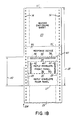
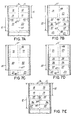
- FIG. 1 B there is shown web 10B which is likewise divided by perforated transverse cutting and folding lines 11' into repeating composite sheets 22.
- Webs 10A and 10B are continuous web forms having line holes 14 that are engaged by a computer directed printer. This permits high speed feeding and proper indexing of the forms for insertion of the personalized messages, and facilitates the bursting operation described below. Webs 10A and 10B are also optionally provided with perforated folding lines 13 and 13', respectively, to facilitate fan folding.
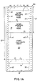
- the composite sheet 12 contains an outer envelope sheet 15 defining a flap 16, to which a remoistenable gum adhesive 17 can be applied.
- Composite sheet 12 also contains an outer envelope front panel 18, an outer envelope rear panel 19 and a first enclosure sheet 20.
- Outer envelope sheet 15 and enclosure sheet 20 are integral, being joined along transverse perforated folding line 13.
- composite sheet 22 contains a second enclosure sheet 23, a response device 35 joined along transverse line 13' to second enclosure sheet 23, and a reply envelope sheet 40 joined along a transverse line of perforations 38 to response device 35.
- the reply envelope sheet 40 defines a reply envelope flap 39, a reply envelope front panel 36 and a reply envelope rear panel 37. Remoistenable gum adhesive 34 can be applied to flap 39.
- the distance between the longitudinal edges of reply envelope sheet 40 is equal to that of sheets 15 and 20.
- Envelope sheet 15 and second enclosure sheet 23 on respective webs 10A and 10B are the same length.
- first enclosure sheet 20 is the same length as the aggregate length of reply envelope sheet 40 and response device 35.
- blank web 10A is fed into a form printer, such as a flexigraphic, lithographic, gravure or letter press. Each of these presses can print, for example, a form letter appropriately positioned to correspond to the field of first enclosure sheet 20 on web 10A.
- a form printer which can print the fields of second enclosure sheet 23 and response device 35.
- This form printer also prints the reply mailing address on reply envelope front panel 36 and optionally a return postage mailing permit and any form message which the sender desires to have within the fields of reply envelope front panel 36 or rear panel 37. Both sides of sheets 20, 23 and response device 35 can be printed, if desired.
- portion 46 can be die-cut and removed by the form printer.
- the transverse width of portion 46 determines the transverse width of response device 35.
- each portion 45 having substantially the configuration shown in Figure 1A, can also be die-cut and removed by the form printer. Their removal lessens the chance of a subsequent trimming operation, described below, leaving unsightly notches in envelope rear panel 19.
- Triangular portions 44 can also be removed by the form printer to provide the desired tapering configuration to the envelope flap 16.
- the shoulder 47, between response device 35 and flap 39, can also be die-cut on the printer to facilitate subsequent bursting steps described below.
- the continuous webs exiting from the form printers are next indexed and fed into computer directed printers for personalization.
- panel 18 of envelope sheet 15 will be printed with the name and address of the recipient.
- first enclosure sheet 20 is in a letter format
- the name and address can be entered and a personal salutation printed, along with any other desired personal data references in the body of the letter.
- Second enclosure sheet 23 may similarly be personalized, with further personal data references in the body of the letter.
- Response device 35 can also advantageously be personalized, as by printing the recipient's name and address to indicate acceptance of a solicitation contained on enclosure sheets 20 and 23.
- the recipient's reply address can be entered either on reply envelope front panel 36 or flap 39. It is also possible to include a unique customer or account number, or other personalized information.
- beads or spots 25 of liquid adhesive or hot melt adhesive are applied just inside the opposite longitudinal edges of either enclosure sheet 20 or reply envelope sheet 40.
- the position of these beads or spots 25 are shown in Figure 1B.
- beads or spots 25 can be applied to a more limited area of either sheets 20 or 40. For example, it is satisfactory to apply -spots 25 only to the lower left portion of reply envelope rear panel 37.
- webs 10A and 10B are brought into an aligned superposed configuration for mating. They are then pressed together so that they are joined and bonded by means of the adhesive beads or spots 25.
- bonding can be accomplished by passing composite sheets 12 and 22 through crimping wheels or other crimping means which are known in the art.
- Composite sheets 12 and 22 remain joined together during subsequent steps and through one of the folding operations.
- the joining of composite sheets 12 and 22 together entirely eliminates any risk of a subsequent mismatching and its attendant waste, and reduces greatly the need for quality control checks on the finished product.
- this method of joining composite sheets 12 and 22 substantially eliminates shifting and misalignment during the high speed folding process.
- Mating and glued webs 10A and 10B are next subject to a line hole slitting and removal operation that occurs on a burster. Specifically, those portions of composite sheet 22 lying outside the field of envelope sheet 15 and first enclosure sheet 20 are removed. In a similar manner, those portions of composite sheet 22 which lie outside the fields of second enclosure sheet 23, response device 35 and reply envelope sheet 40 are removed.
- Line hole slitting and removal preferably is accomplished by appropriately positioned slitting apparatus that makes the necessary longitudinal cuts.
- the longitudinal edge portions of webs 10A and 10B, which contain the line holes, are then removed.
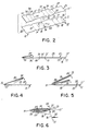
- Figure 2 illustrates, in an exploded perspective view, sections of webs 10A and 10B, comprising adjacent composite sheets following the line hole cutting and removal operation and prior to bursting.
- the burster also separates, or "bursts," the mated sheets along transverse cutting lines 11 and 11'.
- a bead of adhesive 42 is applied inwardly of each opposite longitudinal edge of either reply envelope front panel 36 or rear panel 37. It is preferable to apply adhesive inwardly of the edges of reply envelope front panel 36, as shown in Figure 1 B.
- reply envelope rear panel 37 is folded towards reply envelope front panel 36 along transverse fold line 30.
- This folding step is shown in Figure 3.
- the position of fold line 30 is somewhat less than one third of the distance between, on the first part, the free ends of first enclosure sheet 20 and reply envelope rear panel 37, and, on the second part, perforated folding lines 13 and 13'.
- This fold line position is preferred since it prevents further folding in a subsequent folding step of the free ends of first enclosure sheet 20 and reply envelope rear panel 37, as illustrated in Figure 5.
- reply envelope rear panel 37 Upon folding, reply envelope rear panel 37 is superposed and brought into overlying alignment with reply envelope front panel 36. Pressure is then applied to seal the opposite edges to form a reply envelope pocket.
- Figures 4 through 6 show reply envelope front and rear panels 36 and 37 as separate panels, even though they. are sealed to form a reply envelope pocket, so that the structure produced by the present method can be described with clarity.
- mated and joined composite sheets 12 and 22 are next folded along a second transverse fold line corresponding to perforated fold lines 13 and 13', respectively.
- the opposite longitudinal edges of first enclosure sheet 20, and the reply envelope pocket made from reply envelope front panel 36 and rear panel 37 are trimmed off, as by a cutting wheel.
- the transverse width of the reply envelope pocket is approximately equal to that of second enclosure sheet 23. Since adhesive beads 42 were applied inwardly of the edges that were trimmed, the reply envelope pocket remains intact subsequent to trimming.
- the foregoing trimming operation completely removes those portions of the sheets that were glued together to hold the sheets in a mated aligned superposed configuration.
- no undesirable shifting or misalignment during subsequent processing results, because the two previous folds result in composite sheets 12 and 22 being in a folded and securely nested configuration.
- beads of adhesive are applied along the opposite longitudinal edges of the inside of either outer envelope front or rear panel 18 or 19, and the panel edges are brought into overlying alignment and pressure is applied to seal the opposite edges to form the outer envelope pocket containing the various enclosures. It is preferred that the adhesive be applied to the opposite edges 32 of outer envelope front panel 18, as illustrated in Figure 1A.
- the folded first enclosure sheet 20 is separated from the outer envelope rear panel 19 along line 13 and second enclosure sheet 23 is separated from response device 35 along line 13'.
- These separation operations can advantageously be combined into a single step with the final trimming of the exposed edges that appear behind the front panel of the envelope sheet.
- any portion of second enclosure sheet 23 which overlaps flap 16 should be removed so that the finished envelope can be sealed.
- a slitting device comprising scissor slitting wheels, is adjusted to the thickness of the paper stock to trim cleanly away the layers comprising: both ends of second enclosure sheet 23; portions of first enclosure sheet 20 and outer envelope rear panel 19 lying adjacent to fold line 13; and the portion of response device 35 lying adjacent to fold line 13'.
- the paper to be trimmed is made accessible to the slitting device by means of a flap deflector 50, which temporarily bends down outer envelope flap 16.
- the edges of the above-identified materials can then be passed into slitting wheels 55.
- Figure 6, is a cutaway sectional view showing the enclosures and upper edge of rear envelope panel 19 being engaged by cutting wheels 55, while flap 16 is held out of the way by flap deflector 50.
- this particular embodiment of the method of this invention results in a personalized envelope containing two separate enclosure sheets in a nested configuration with a preformed reply envelope, to which is detachably connected a response device.
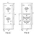
- FIG. 1C there is shown a third web 10C which is divided by perforated cutting lines 11" into repeating composite sheets 62.
- Composite sheet 62 contains a third enclosure sheet 70 and a fourth enclosure sheet 80.
- Perforated folding lines 13" are again preferably provided to facilitate fan folding.
- third enclosure sheet 70 are positioned inside the longitudinal edges of fourth enclosure sheet 80.
- fourth enclosure sheet 80 The distance between the longitudinal edges of fourth enclosure sheet 80 is equal to that of first enclosure sheet 20 and outer envelope rear panel 19.
- web 10C can be aligned in a superposed configuration between webs 10A and 10B so that response device 35 and reply envelope sheet 40 are over fourth enclosure sheet 80, which in turn is over first enclosure sheet 20, and second enclosure sheet 23 is over third enclosure sheet 70 which in turn is over envelope sheet 15.
- the three webs 10A, 10B, and 10C can be moved as a unit.
- the method of fabrication described above for two webs is substantially identical to the method used for three webs.
- the only additional necessary step is the application of beads or spots of adhesive 85 to fourth enclosure sheet 80 at a position just inside of its opposite longitudinal edges prior to bringing the webs together in an aligned and mated configuration. After the webs are joined and bonded together, subsequent processing is identical to that employed with two webs only.
- FIG. 1D shows web 10D, wherein the longitudinal dimensions of flap 39, reply envelope front panel 36 and reply envelope rear panel 37 are increased so that response device 35 is eliminated.
- Web 10D can be used according to the methods described above. Web 10D can also be used in combination with web 10C to provide additional enclosure sheets as desired.
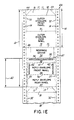
- FIG. 1E Yet another embodiment of the present invention is shown in Figure 1E.
- response device 35 is joined along transverse line 13 to outer envelope rear panel 19, and reply envelope 40 is joined along transverse line of perforations 38 to response device 35.
- composite sheet 12 comprises outer envelope panel 15, response device 35 and reply envelope panel 40.
- This embodiment results in a personalized outer envelope containing a response device detachably connected to a preformed reply envelope. It is useful where the response device satisfactorily serves to contain both the sender's message and the recipient's reply, such that other enclosures would prove unnecessary.
- a second composite sheet eithei as shown in Figures 1 B or 1D, is not used with the embodiment shown in Figure 1E. Nonetheless, the folding and gluing steps illustrated in and associated with Figures 3 through 5 are equally applicable to the embodiment of Figure 1E.
- Figures 7A, 7B, 7C, 7D and 7E typical parallel composite sheets, each of which comprises a line hole punch paper web containing in parallel configuration, pairs of sheets corresponding respectively to those shown in Figures 1A, 1B, 1C, 1D and 1E.
- the parts of Figure 7 correspond to those of Figure 1.
Landscapes
- Credit Cards Or The Like (AREA)
Claims (15)
dadurch gekennzeichnet, daß das weitere Blatt (40) ein Antwortumschlagsblatt aufweist mit einer Klappe (39), einer Vorderseite (36) und einer Rückseite (37); und
Applications Claiming Priority (2)
| Application Number | Priority Date | Filing Date | Title |
|---|---|---|---|
| US330320 | 1981-12-14 | ||
| US06/330,320 US4437852A (en) | 1981-12-14 | 1981-12-14 | Method of producing mailer with self contained reply envelope |
Publications (3)
| Publication Number | Publication Date |
|---|---|
| EP0082004A2 EP0082004A2 (de) | 1983-06-22 |
| EP0082004A3 EP0082004A3 (en) | 1985-01-02 |
| EP0082004B1 true EP0082004B1 (de) | 1988-05-11 |
Family
ID=23289242
Family Applications (1)
| Application Number | Title | Priority Date | Filing Date |
|---|---|---|---|
| EP82306636A Expired EP0082004B1 (de) | 1981-12-14 | 1982-12-13 | Verfahren zur Herstellung eines Versandmittels mit beigefügtem Antwortumschlag |
Country Status (4)
| Country | Link |
|---|---|
| US (1) | US4437852A (de) |
| EP (1) | EP0082004B1 (de) |
| CA (1) | CA1199210A (de) |
| DE (1) | DE3278464D1 (de) |
Families Citing this family (32)
| Publication number | Priority date | Publication date | Assignee | Title |
|---|---|---|---|---|
| US4543082A (en) * | 1982-09-17 | 1985-09-24 | Kurt H. Volk, Inc. | Method of making direct mail article with reply envelope and detachable reply devices visible within reply envelope |
| US4651920A (en) * | 1982-09-17 | 1987-03-24 | Kurt H. Volk, Inc. | Direct mail article with reply envelope and detachable reply devices visible within reply envelope |
| US4668212A (en) * | 1984-12-19 | 1987-05-26 | Iseto Shiko Co. Ltd. | Process for manufacturing sealed postal envelope assemblies |
| GB2180501A (en) * | 1985-09-20 | 1987-04-01 | Promotions Impressions Limited | Personalised data carrying assembly and method and apparatus for forming same |
| US4731142A (en) * | 1987-04-24 | 1988-03-15 | Kurt H. Volk, Inc. | Method of making a personalized folder with pockets and page inserts from a continuous web |
| US4972655A (en) * | 1987-06-30 | 1990-11-27 | Iseto Shiko Co., Ltd. | Apparatus for manufacturing sealed postal mails or the like envelope assemblies |
| DE3889222D1 (de) * | 1988-03-04 | 1994-05-26 | Volk Inc Kurt H | Gegenstand für den unmittelbaren versand per post mit einer postversandfähigen antwortkarte. |
| US4960237A (en) * | 1988-08-09 | 1990-10-02 | Bruce Bendel | Self-contained insert mailer |
| US4915287A (en) * | 1988-11-03 | 1990-04-10 | Moore Business Forms, Inc. | Intelligently imaged envelopes with intelligently imaged integral tear-off flaps |
| US5039000A (en) * | 1990-02-22 | 1991-08-13 | Moore Business Forms, Inc. | Mailer with tear strip on outgoing and return envelopes |
| US5071399A (en) * | 1990-02-22 | 1991-12-10 | Moore Business Forms, Inc. | Method of making a mailer with tear strip on outgoing and return envelopes |
| US5196083A (en) * | 1990-03-12 | 1993-03-23 | Pitney Bowes Inc. | System and method for producing items in selected configurations |
| US5104036A (en) * | 1990-07-11 | 1992-04-14 | Avery International Corporation | Mailer with reply envelope |
| US5064115A (en) * | 1990-08-06 | 1991-11-12 | Wallace Computer Services, Inc. | Mailer and method and apparatus for making |
| US5568717A (en) * | 1993-03-30 | 1996-10-29 | Moore Business Forms, Inc. | Forming an envelope around inserts |
| US5366146A (en) * | 1993-07-09 | 1994-11-22 | Moore Business Forms, Inc. | Single-part statement mailer |
| US5607100A (en) * | 1994-08-12 | 1997-03-04 | Kurt H. Volk, Inc. | Direct mail packet with plurality of detachably joined envelopes and method of manufacture |
| US5797541A (en) * | 1995-05-24 | 1998-08-25 | Kurt H. Volk, Inc. | Direct mail article comprising oversized card and integral envelope and reply device and method of manufacture |
| US7100348B2 (en) * | 1996-03-06 | 2006-09-05 | Megaspirea N.V. | Continuous strip of detachably interconnected folded products |
| US5967403A (en) * | 1998-07-01 | 1999-10-19 | Tension Envelope Corporation | Remailable envelope and method for making a remailable envelope from a single blank |
| US20040101646A1 (en) * | 2001-05-22 | 2004-05-27 | Hodsdon Jerry G. | Compact disc label construction |
| US7275678B2 (en) * | 2002-04-19 | 2007-10-02 | Avery Dennison Corporation | Printable envelope with removable business card for compact discs |
| US7260921B2 (en) * | 2002-12-16 | 2007-08-28 | Pitney Bowes Inc. | Method and apparatus for enveloping documents |
| US20050051613A1 (en) * | 2003-09-09 | 2005-03-10 | William Settle | Mailer and method of forming mailers |
| US7254931B2 (en) * | 2005-02-18 | 2007-08-14 | Pitney Bowes Inc. | Method and system for creating mailpieces from a single continuous web of printed material |
| US7357080B2 (en) * | 2005-02-18 | 2008-04-15 | Pitney Bowes Inc. | Method for creating a single continuous web from which to fabricate mailpieces |
| US7231750B2 (en) * | 2005-02-18 | 2007-06-19 | Pitney Bowes Inc. | Method and system for creating mailpieces from a single continuous web of printed material |
| FR2888774A1 (fr) * | 2005-07-25 | 2007-01-26 | Megaspirea Production Soc Par | Procede de fabrication de plis courriers et machine mettant en oeuvre ledit procede |
| US9604493B2 (en) * | 2009-11-25 | 2017-03-28 | Bell And Howell, Llc | Method and system to manufacture an integrated return mailpiece on wrapping document processing system |
| US8544720B2 (en) * | 2009-11-25 | 2013-10-01 | Bell And Howell, Llc | Article of manufacture for usage as an integrated bidirectional mailpiece and method of manufacturing integrated bidirectional mailpieces |
| US20110192892A1 (en) * | 2010-02-09 | 2011-08-11 | Bowe Bell + Howell Company | Mailpiece with personalized communication and return slip and related method utilizing wrapper system |
| GB201519859D0 (en) * | 2015-11-10 | 2015-12-23 | Inline Graphic Solutions Ltd | Method and apparatus |
Family Cites Families (8)
| Publication number | Priority date | Publication date | Assignee | Title |
|---|---|---|---|---|
| CA572222A (en) | 1959-03-17 | B. Coffin Harry | Mailing piece including return envelope forming portion | |
| US3557519A (en) | 1968-09-04 | 1971-01-26 | Volk Inc Kurt H | Combination letter sheet and envelope |
| US3579947A (en) | 1969-04-07 | 1971-05-25 | Goodway Inc | Method of printing and folding a mailing piece |
| US3955750A (en) | 1974-05-13 | 1976-05-11 | Huffman Harold W | Multi-panel envelope form |
| US4071997A (en) * | 1976-04-27 | 1978-02-07 | Gunther Business Systems, Inc. | Mechanism and method of making an envelope |
| US4067171A (en) | 1977-02-07 | 1978-01-10 | Kurt H. Volk, Inc. | Method of making multiple enclosure mailer |
| US4189895A (en) * | 1977-12-16 | 1980-02-26 | Compak Systems, Inc. | Method and apparatus for making envelope assemblies |
| US4161091A (en) | 1978-03-08 | 1979-07-17 | Paper Converting Machine Company | Apparatus for making a connected series of stuffed sealed envelope assemblies |
-
1981
- 1981-12-14 US US06/330,320 patent/US4437852A/en not_active Expired - Lifetime
-
1982
- 1982-12-13 CA CA000417522A patent/CA1199210A/en not_active Expired
- 1982-12-13 EP EP82306636A patent/EP0082004B1/de not_active Expired
- 1982-12-13 DE DE8282306636T patent/DE3278464D1/de not_active Expired
Also Published As
| Publication number | Publication date |
|---|---|
| CA1199210A (en) | 1986-01-14 |
| US4437852A (en) | 1984-03-20 |
| EP0082004A3 (en) | 1985-01-02 |
| EP0082004A2 (de) | 1983-06-22 |
| DE3278464D1 (en) | 1988-06-16 |
Similar Documents
| Publication | Publication Date | Title |
|---|---|---|
| EP0082004B1 (de) | Verfahren zur Herstellung eines Versandmittels mit beigefügtem Antwortumschlag | |
| EP0104067B1 (de) | Briefumschlag mit einem Rückumschlag und verschiedenen abtrennbaren und durch den Rückumschlag sichtbaren Antworteinlagen | |
| CA1066935A (en) | Multiple enclosure mailer | |
| US4651920A (en) | Direct mail article with reply envelope and detachable reply devices visible within reply envelope | |
| US4915287A (en) | Intelligently imaged envelopes with intelligently imaged integral tear-off flaps | |
| US4912909A (en) | Direct mail article with mailable reply card | |
| EP0288131B1 (de) | Fensterbriefumschlag mit Rückumschlag | |
| US4852795A (en) | Mailing cover with reply envelope and response device made from integral web | |
| US6053855A (en) | Direct mail article with cover and one or more interior sheets and integral business reply envelope | |
| US5797541A (en) | Direct mail article comprising oversized card and integral envelope and reply device and method of manufacture | |
| EP0354758A1 (de) | Verschlossener Faltbrief für Einlagen | |
| EP0364500B1 (de) | Broschüre mit zentralem, abreissbarem geschäftsrückumschlag und wahlweiser bantwortungsanordnung, hergestellt aus einer einzigen bahn sowie herstellungsverfahren | |
| EP0274822B1 (de) | Verfahren zum Herstellen eines mit Personendaten versehenen Faltblattes mit Taschen und Beilagen aus einer endlosen Bahn | |
| US4726802A (en) | Mailing cover with reply envelope and response device from integral web | |
| EP0562788A1 (de) | Einteiliges Poststück und Verfahren zu seiner Herstellung | |
| US5031382A (en) | Return card system | |
| US6402022B1 (en) | Mailing form for non-impact printing | |
| US5263637A (en) | Self-mailer with return order envelope and the method for producing the same | |
| CA2007682A1 (en) | Dual mailer construction | |
| EP0128738B1 (de) | Sendumschlag mit darin enthaltenem Rückumschlag und Antwortvorrichtung | |
| US5607100A (en) | Direct mail packet with plurality of detachably joined envelopes and method of manufacture | |
| EP0695649A1 (de) | Einteiliges Poststück und Verfahren zu seiner Herstellung | |
| JPH0517267Y2 (de) | ||
| EP0349128A2 (de) | Informationsanzeige mit einer gleitenden Datenkarte | |
| GB1590307A (en) | Set of sub-assemblies for forming envelopes mailers or the like |
Legal Events
| Date | Code | Title | Description |
|---|---|---|---|
| PUAI | Public reference made under article 153(3) epc to a published international application that has entered the european phase |
Free format text: ORIGINAL CODE: 0009012 |
|
| AK | Designated contracting states |
Designated state(s): BE DE FR GB IT NL |
|
| PUAL | Search report despatched |
Free format text: ORIGINAL CODE: 0009013 |
|
| AK | Designated contracting states |
Designated state(s): BE DE FR GB IT NL |
|
| 17P | Request for examination filed |
Effective date: 19850607 |
|
| 17Q | First examination report despatched |
Effective date: 19860321 |
|
| ITF | It: translation for a ep patent filed | ||
| GRAA | (expected) grant |
Free format text: ORIGINAL CODE: 0009210 |
|
| AK | Designated contracting states |
Kind code of ref document: B1 Designated state(s): BE DE FR GB IT NL |
|
| REF | Corresponds to: |
Ref document number: 3278464 Country of ref document: DE Date of ref document: 19880616 |
|
| ET | Fr: translation filed | ||
| PLBE | No opposition filed within time limit |
Free format text: ORIGINAL CODE: 0009261 |
|
| STAA | Information on the status of an ep patent application or granted ep patent |
Free format text: STATUS: NO OPPOSITION FILED WITHIN TIME LIMIT |
|
| 26N | No opposition filed | ||
| ITTA | It: last paid annual fee | ||
| PGFP | Annual fee paid to national office [announced via postgrant information from national office to epo] |
Ref country code: DE Payment date: 19941230 Year of fee payment: 13 |
|
| PGFP | Annual fee paid to national office [announced via postgrant information from national office to epo] |
Ref country code: NL Payment date: 19950918 Year of fee payment: 14 |
|
| PGFP | Annual fee paid to national office [announced via postgrant information from national office to epo] |
Ref country code: FR Payment date: 19950920 Year of fee payment: 14 |
|
| PGFP | Annual fee paid to national office [announced via postgrant information from national office to epo] |
Ref country code: GB Payment date: 19950922 Year of fee payment: 14 |
|
| PGFP | Annual fee paid to national office [announced via postgrant information from national office to epo] |
Ref country code: BE Payment date: 19950926 Year of fee payment: 14 |
|
| PG25 | Lapsed in a contracting state [announced via postgrant information from national office to epo] |
Ref country code: DE Effective date: 19960903 |
|
| PG25 | Lapsed in a contracting state [announced via postgrant information from national office to epo] |
Ref country code: GB Effective date: 19961213 |
|
| PG25 | Lapsed in a contracting state [announced via postgrant information from national office to epo] |
Ref country code: BE Effective date: 19961231 |
|
| BERE | Be: lapsed |
Owner name: KURT H. VOLK INC. Effective date: 19961231 |
|
| PG25 | Lapsed in a contracting state [announced via postgrant information from national office to epo] |
Ref country code: NL Effective date: 19970701 |
|
| GBPC | Gb: european patent ceased through non-payment of renewal fee |
Effective date: 19961213 |
|
| PG25 | Lapsed in a contracting state [announced via postgrant information from national office to epo] |
Ref country code: FR Effective date: 19970829 |
|
| NLV4 | Nl: lapsed or anulled due to non-payment of the annual fee |
Effective date: 19970701 |
|
| REG | Reference to a national code |
Ref country code: FR Ref legal event code: ST |