EP0081978B1 - Kathodenstrahlanzeigeeinrichtung mit einem rekonfigurierbaren Format - Google Patents
Kathodenstrahlanzeigeeinrichtung mit einem rekonfigurierbaren Format Download PDFInfo
- Publication number
- EP0081978B1 EP0081978B1 EP82306566A EP82306566A EP0081978B1 EP 0081978 B1 EP0081978 B1 EP 0081978B1 EP 82306566 A EP82306566 A EP 82306566A EP 82306566 A EP82306566 A EP 82306566A EP 0081978 B1 EP0081978 B1 EP 0081978B1
- Authority
- EP
- European Patent Office
- Prior art keywords
- deflection
- signals
- horizontal
- display
- ray tube
- Prior art date
- Legal status (The legal status is an assumption and is not a legal conclusion. Google has not performed a legal analysis and makes no representation as to the accuracy of the status listed.)
- Expired
Links
- 238000010894 electron beam technology Methods 0.000 claims description 12
- 230000008859 change Effects 0.000 claims description 3
- 230000008878 coupling Effects 0.000 claims description 2
- 238000010168 coupling process Methods 0.000 claims description 2
- 238000005859 coupling reaction Methods 0.000 claims description 2
- 230000007246 mechanism Effects 0.000 description 9
- 238000010586 diagram Methods 0.000 description 3
- 230000001419 dependent effect Effects 0.000 description 2
- 238000000034 method Methods 0.000 description 2
- 230000009471 action Effects 0.000 description 1
- 238000009125 cardiac resynchronization therapy Methods 0.000 description 1
- JBTHDAVBDKKSRW-UHFFFAOYSA-N chembl1552233 Chemical compound CC1=CC(C)=CC=C1N=NC1=C(O)C=CC2=CC=CC=C12 JBTHDAVBDKKSRW-UHFFFAOYSA-N 0.000 description 1
- 230000000694 effects Effects 0.000 description 1
- 230000035515 penetration Effects 0.000 description 1
Images

Classifications
-
- G—PHYSICS
- G09—EDUCATION; CRYPTOGRAPHY; DISPLAY; ADVERTISING; SEALS
- G09G—ARRANGEMENTS OR CIRCUITS FOR CONTROL OF INDICATING DEVICES USING STATIC MEANS TO PRESENT VARIABLE INFORMATION
- G09G1/00—Control arrangements or circuits, of interest only in connection with cathode-ray tube indicators; General aspects or details, e.g. selection emphasis on particular characters, dashed line or dotted line generation; Preprocessing of data
- G09G1/04—Deflection circuits ; Constructional details not otherwise provided for
-
- G—PHYSICS
- G09—EDUCATION; CRYPTOGRAPHY; DISPLAY; ADVERTISING; SEALS
- G09G—ARRANGEMENTS OR CIRCUITS FOR CONTROL OF INDICATING DEVICES USING STATIC MEANS TO PRESENT VARIABLE INFORMATION
- G09G1/00—Control arrangements or circuits, of interest only in connection with cathode-ray tube indicators; General aspects or details, e.g. selection emphasis on particular characters, dashed line or dotted line generation; Preprocessing of data
- G09G1/28—Control arrangements or circuits, of interest only in connection with cathode-ray tube indicators; General aspects or details, e.g. selection emphasis on particular characters, dashed line or dotted line generation; Preprocessing of data using colour tubes
- G09G1/285—Interfacing with colour displays, e.g. TV receiver
Definitions
- This invention relates to a CRT display, and more particularly, to such a CRT including means for quickly and easily rotating the format to an alternate configuration.
- a cathode ray tube (CRT) 10 having at least one electron beam is provided as are deflection means including a deflection yoke 12 mounted upon the neck of the CRT for receiving deflection signals from deflection circuit 20 for effecting deflection of the at least one electron beam.
- deflection means including a deflection yoke 12 mounted upon the neck of the CRT for receiving deflection signals from deflection circuit 20 for effecting deflection of the at least one electron beam.
- Means are provided in the form of switching mechanism 30 for redirecting the deflection signals to effect reconfiguration of the display presentation.
- channel S is the normal horizontal deflection channel and it provides deflection signals to what are normally the horizontal coils 13 and 13'
- channel T is the normal vertical deflection and its deflection signals are provided to coils 14 and 14'
- deflection signals will be provided through the switch mechanism 30 as shown in Figure 2.
- switches 31, 32, 33 and 34 can be rotated from contact with the A position to the B position, thereby to reconfigure the circuit.
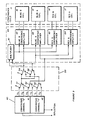
- the convergence coil assembly 11 includes a blue convergence A coil 15 and a blue convergence B coil 16, a red convergence A coil 17 and a red convergence B coil 18.
- the convergence circuitry 40 which has inputs from the deflection circuit 20 as shown in Figure 1, includes two channels: S convergence channel 41 and T convergence channel 42.
- S convergence channel 41 provides three output signals S1, S2 and S3 and T convergence channel 42 provides likewise three output signals, T1, T2, and T3.
- Switch mechanism 50 includes a plurality of switches 51, 52, 53, 54 and 55.
- Switches 51, 52 and 53 are of the single-pole, double-throw type and are arranged to receive convergence signals from the convergence channels 41 and 42. As determined by the specific state of arrangement of switches 51, 52, 53, 54 and 55, three of the six input convergence correction signals (S1, S2, S3, T1, T2, T3) are selected and applied to the convergence amplifier, dynamic convergence module 60.
- Blue B convergence amplifier combines its two respective input signals and, through active drive techniques, provides a proportional current in its associated beam convergence coil (Blue B).
- Convergence amplifiers 62, 63 and 64 function in a similar manner as just described.
- switch 30 redirects the output signals from deflection channels "S" and "T” to the magnetic deflection yoke 12 which is of the single ended form.
- Coils 13 and 13' constitute a beam position mechanism for one axis of CRT deflection.
- Coils 14 and 14' similarly constitute a beam positioning mechanism for the other axis of CRT deflection.
- the "S” OUTPUT is routed through switch 31 to one side of deflection coil 13.
- the current thus produced by action of this "S” OUTPUT drive signal flows through coil 13' and is returned to deflection channel "S" through switch 32.
- the "T” OUTPUT drive signal applied to coil 14 through switch 33, produces a resulting current which flows through coil 14' and is returned to deflection channel "T" through switch 34.
- switch 50 consists of five inddividual switches of the single-pole, double-throw type - 51, 52, 53, 54 and 55. With the switches arranged as shown, the switches collectively redirect the six input signals from convergence channels "S" and "T” into three output signals which provide the correction terms required to converge the three beams of the color CRT. As can be seen, input signal S 1 is routed through switches 51 and 54 to form one of the output signals.
- signal S 3 is selected by switch 52 and appears as the second output correction signal.
- input signal T1 is routed through the contacts of switches 53 and 55 to provide the third output correction signal.
- any three of the six input signals can be redirected to the output signal lines from switch 50.
- the exact arrangement of the selected output signals is dependent on the reqirement of the mathematical equations used to converge the beams of the CRT.
- a display format may be reconfigured in a multitude of ways over and above those described herein.
- the horizontal scan lines may proceed from right to left of the viewed screen as opposed to the typical left to right for the horizontal scan lines.
- one may scan from right to left but the vertical movement may be from bottom to top; such is also within the contemplation of the present invention.
- the switching technique described can be expanded to provide any orientation of the displayed picture with respect to the display mounting.
- alternate forms of switching may be utilized such as, for example, electrically driven relays and electronic switches in addition to the mechanical type described and shown herein.
Landscapes
- Engineering & Computer Science (AREA)
- Radar, Positioning & Navigation (AREA)
- Remote Sensing (AREA)
- Physics & Mathematics (AREA)
- Computer Hardware Design (AREA)
- General Physics & Mathematics (AREA)
- Theoretical Computer Science (AREA)
- Video Image Reproduction Devices For Color Tv Systems (AREA)
Claims (3)
Applications Claiming Priority (2)
| Application Number | Priority Date | Filing Date | Title |
|---|---|---|---|
| US329215 | 1981-12-10 | ||
| US06/329,215 US4551657A (en) | 1981-12-10 | 1981-12-10 | Format reconfigurable CRT display |
Publications (3)
| Publication Number | Publication Date |
|---|---|
| EP0081978A2 EP0081978A2 (de) | 1983-06-22 |
| EP0081978A3 EP0081978A3 (en) | 1983-08-10 |
| EP0081978B1 true EP0081978B1 (de) | 1986-10-29 |
Family
ID=23284382
Family Applications (1)
| Application Number | Title | Priority Date | Filing Date |
|---|---|---|---|
| EP82306566A Expired EP0081978B1 (de) | 1981-12-10 | 1982-12-09 | Kathodenstrahlanzeigeeinrichtung mit einem rekonfigurierbaren Format |
Country Status (4)
| Country | Link |
|---|---|
| US (1) | US4551657A (de) |
| EP (1) | EP0081978B1 (de) |
| JP (1) | JPS58108576A (de) |
| DE (1) | DE3274029D1 (de) |
Families Citing this family (9)
| Publication number | Priority date | Publication date | Assignee | Title |
|---|---|---|---|---|
| US4631454A (en) * | 1985-03-25 | 1986-12-23 | Ballard Paul T | Quasi-resonant random access deflection system for a calligraphic display monitor |
| US4782270A (en) * | 1987-04-30 | 1988-11-01 | Ncr Corporation | CRT raster reversal board |
| US4876488A (en) * | 1987-09-30 | 1989-10-24 | The Boeing Company | Raster rotation circuit |
| US6437829B1 (en) | 1997-01-16 | 2002-08-20 | Display Laboratories, Inc. | Alignment of cathode ray tube displays using a video graphics controller |
| US6285397B1 (en) | 1997-01-16 | 2001-09-04 | Display Laboratories, Inc. | Alignment of cathode ray tube video displays using a host computer processor |
| US5969486A (en) * | 1997-01-16 | 1999-10-19 | Display Laboratories, Inc. | Detecting horizontal blanking time in cathode ray tube devices |
| US6417133B1 (en) | 1998-02-25 | 2002-07-09 | Monsanto Technology Llc | Deeply reduced oxidation catalyst and its use for catalyzing liquid phase oxidation reactions |
| CN103368539B (zh) * | 2012-03-26 | 2016-08-31 | 通用电气公司 | 开关元件和开关系统 |
| US9739611B2 (en) * | 2013-10-09 | 2017-08-22 | Mid-Continent Instruments Co., Inc. | Aircraft instrumentation module |
Family Cites Families (4)
| Publication number | Priority date | Publication date | Assignee | Title |
|---|---|---|---|---|
| US2287307A (en) * | 1940-10-29 | 1942-06-23 | Farnsworth Television & Radio | Television receiving system |
| US3435276A (en) * | 1966-02-14 | 1969-03-25 | Rca Corp | Convergence apparatus for nullifying unwanted induced deflection currents |
| US4183063A (en) * | 1978-06-26 | 1980-01-08 | Lewis Earl C | Electronic switching means for television projection arrangement |
| US4267555A (en) * | 1979-06-29 | 1981-05-12 | International Business Machines Corporation | Rotatable raster scan display |
-
1981
- 1981-12-10 US US06/329,215 patent/US4551657A/en not_active Expired - Fee Related
-
1982
- 1982-12-09 EP EP82306566A patent/EP0081978B1/de not_active Expired
- 1982-12-09 DE DE8282306566T patent/DE3274029D1/de not_active Expired
- 1982-12-10 JP JP57215621A patent/JPS58108576A/ja active Pending
Also Published As
| Publication number | Publication date |
|---|---|
| US4551657A (en) | 1985-11-05 |
| DE3274029D1 (en) | 1986-12-04 |
| JPS58108576A (ja) | 1983-06-28 |
| EP0081978A3 (en) | 1983-08-10 |
| EP0081978A2 (de) | 1983-06-22 |
Similar Documents
| Publication | Publication Date | Title |
|---|---|---|
| EP0376332B1 (de) | Wiedergabevorrichtung | |
| EP0081978B1 (de) | Kathodenstrahlanzeigeeinrichtung mit einem rekonfigurierbaren Format | |
| JP2611942B2 (ja) | カラー表示装置及びカラー陰極線管 | |
| EP0235894A1 (de) | Farbkathodenstrahlrohrvorrichtung | |
| KR960706185A (ko) | 다중-모드의, 하이브리드타입의 음극선관 및 그에 대한 전자총 | |
| US4758884A (en) | Electronically switched field sequential color video display having parallel color inputs | |
| US4788470A (en) | Deflection yoke apparatus with compensation magnetic field generating means | |
| KR0141589B1 (ko) | 칼라음극선관시스템및편향유니트 | |
| KR930002655B1 (ko) | 컬러음극선관내에서 수렴을 개선하기 위한 유효한 전극을 가진 전자총과 그것을 구비한 컬러음극선관 | |
| US4130829A (en) | Apparatus for adjusting operating conditions of a cathode ray tube | |
| EP0913851A2 (de) | Farbkathodenstrahlröhre | |
| US4217566A (en) | In-line type color picture tube apparatus | |
| GB2085698A (en) | Stigmator for cathode ray tube | |
| US3789258A (en) | Electron beam and deflection yoke alignment for producing convergence of plural in-line beams | |
| US5498939A (en) | Deflection yoke and cathode ray tube having the same | |
| US4633143A (en) | Convergence correction apparatus for delta-gun color cathode ray tube displays | |
| EP0660364B1 (de) | Anzeigegerät mit Ablenkeinheit | |
| US4763040A (en) | Picture display device | |
| US5491382A (en) | Color picture tube apparatus | |
| US4039987A (en) | Color television display device | |
| US5644197A (en) | Cathode ray tube display apparatus with rotatable raster | |
| EP0823724B1 (de) | Kathodenstrahlröhre | |
| US4375046A (en) | Network and method for correcting vertical non-linearity and mis-convergence in a television projection system | |
| USRE31552E (en) | Electron beam and deflection yoke alignment for producing convergence of plural in-line beams | |
| CA1339621C (en) | Video display system |
Legal Events
| Date | Code | Title | Description |
|---|---|---|---|
| PUAI | Public reference made under article 153(3) epc to a published international application that has entered the european phase |
Free format text: ORIGINAL CODE: 0009012 |
|
| PUAL | Search report despatched |
Free format text: ORIGINAL CODE: 0009013 |
|
| AK | Designated contracting states |
Designated state(s): DE FR GB IT |
|
| AK | Designated contracting states |
Designated state(s): DE FR GB IT |
|
| 17P | Request for examination filed |
Effective date: 19840114 |
|
| GRAA | (expected) grant |
Free format text: ORIGINAL CODE: 0009210 |
|
| AK | Designated contracting states |
Kind code of ref document: B1 Designated state(s): DE FR GB IT |
|
| REF | Corresponds to: |
Ref document number: 3274029 Country of ref document: DE Date of ref document: 19861204 |
|
| ITF | It: translation for a ep patent filed | ||
| ET | Fr: translation filed | ||
| PLBE | No opposition filed within time limit |
Free format text: ORIGINAL CODE: 0009261 |
|
| STAA | Information on the status of an ep patent application or granted ep patent |
Free format text: STATUS: NO OPPOSITION FILED WITHIN TIME LIMIT |
|
| 26N | No opposition filed | ||
| GBPC | Gb: european patent ceased through non-payment of renewal fee | ||
| PG25 | Lapsed in a contracting state [announced via postgrant information from national office to epo] |
Ref country code: FR Free format text: LAPSE BECAUSE OF NON-PAYMENT OF DUE FEES Effective date: 19880831 |
|
| PG25 | Lapsed in a contracting state [announced via postgrant information from national office to epo] |
Ref country code: DE Effective date: 19880901 |
|
| REG | Reference to a national code |
Ref country code: FR Ref legal event code: ST |
|
| PG25 | Lapsed in a contracting state [announced via postgrant information from national office to epo] |
Ref country code: GB Free format text: LAPSE BECAUSE OF NON-PAYMENT OF DUE FEES Effective date: 19881122 |