EP0081620A2 - Grout injection method and apparatus - Google Patents
Grout injection method and apparatus Download PDFInfo
- Publication number
- EP0081620A2 EP0081620A2 EP82100809A EP82100809A EP0081620A2 EP 0081620 A2 EP0081620 A2 EP 0081620A2 EP 82100809 A EP82100809 A EP 82100809A EP 82100809 A EP82100809 A EP 82100809A EP 0081620 A2 EP0081620 A2 EP 0081620A2
- Authority
- EP
- European Patent Office
- Prior art keywords
- injection
- grout
- pipe member
- pipe
- liquid
- Prior art date
- Legal status (The legal status is an assumption and is not a legal conclusion. Google has not performed a legal analysis and makes no representation as to the accuracy of the status listed.)
- Granted
Links
Images


Classifications
-
- E—FIXED CONSTRUCTIONS
- E02—HYDRAULIC ENGINEERING; FOUNDATIONS; SOIL SHIFTING
- E02D—FOUNDATIONS; EXCAVATIONS; EMBANKMENTS; UNDERGROUND OR UNDERWATER STRUCTURES
- E02D3/00—Improving or preserving soil or rock, e.g. preserving permafrost soil
- E02D3/12—Consolidating by placing solidifying or pore-filling substances in the soil
Definitions
- This invention relates to a grout injection method and apparatus for injecting a grout into the ambient earth.
- a grout injection method has been widely employed for the stabilization of a poor subsoil and developed after many changes. Among these changes, a view point of the penetration of a grout has also been changed.
- the penetration of the grout into the soil should be effected slowly to provide effective stabilization of the ground, and a grout having a gellation time of at least 60 seconds, usually, as long as several minutes to several tenminutes was employed. In fact, this method is very effective for the stabilization of a homogeneous sandy soil.
- a slow-curable grout having a long gellation time does not work effectively in a heterogeneous poor subsoil such as a diluvium deposit or an alluvium deposit, a sandy soil abundantly containing ground water, or a complicated ground condition with cohesive soil mingled.
- the slow-curable grout may often be diluted by ground water contained in the soil, during the grout injection operation, to such an extent that the desired compression strength of the stabilized mass cannot be developed, or escaped with the ground water from the area to be treated, or flowed out the surface through a gap between an injection pipe and a wall of a bored hole.
- the slow-curable grout requires a long hardening time and accordingly requires a long standby time. By these reasons, the slow-curable grout is not always effective and not economical.
- the spool valve is normally in an unoperated position, so as to jet a boring water pumped into a first flow passage formed in an outer pipe member, through a nozzle provided at a tip end of the boring and injecting pipe.
- a grout comprised of two liquids which are hardened when combined (hereinafter referred to as "two-liquid type grout") is fed through the first passage and a second passage, respectively, so that the spool valve is pressed down by the liquid fed through the second passage to feed the liquid into a mixing space.
- the liquid fed through the first passage is prevented from flowing to the nozzle but allowed to flow, from the first passage, into the mixing chamber.
- the two.liquids are combined, contacted and mixed with each other.
- the mixing chamber should be provided within the injection pipe so as to allow the liquids to be combined, contacted and mixed in the mixing chamber before injection of the grout.
- the liquids cannot always be mixed sufficiently because the mixing space of the conventional injection pipe is a narrow, restricted space and is located on one side of the injection pipe and, in addition, the liquids are discharged in linear forms to be combined with each other.
- the injection pipe should be rotated around its axis, during the injection operation, for providing uniform solidification around the injection pipe, because only one injection orifice is provided in the injection pipe.
- the spool valve does not always operate smoothly, because the liquid in the first passage is forced to flow around or through the spool valve.
- the inventors have made intensive and extensive study with a view to solving the problems as described above and found that (1) the structure can be simplified and the operation of the spool valve can be more smooth by an arrangement in which the liquid in the first passage communicates directly with the mixing chamber instead of introducing the liquid into the mixing chamber from a by-pass formed between the outer and inner pipe members, traversing the spool valve, and (2.) a plurality of injection orifices can be provided by providing an annular mixing chamber, to enable uniform injection in the limited area around the injection pipe, without rotating the injection pipe around its axis.
- the inventors have made the present invention.
- a grout injection method for injecting a grout composed of a first liquid and a second liquid and curable when the liquids are combined which. comprises: feeding said first liquid through a peripheral portion of an injection pipe comprised of an inner pipe member and an outer pipe member having one or more injection orifices formed in the sidewall thereof, in parallel with the axis of said injection pipe, to introduce said first liquid into an annular mixing chamber; feeding said second liquid to said inner pipe member to depress, by a.pressure of the liquid, a spool valve fitted in said inner pipe member, so as to introduce said second liquid into said annular mixing chamber, combining, contacting and mixing the liquids in said annular mixing chamber; and injecting the mixture of the liquids into the ambient soil through said one or more injection orifices.
- a grout injection apparatus comprising an injection pipe which comprises: an inner pipe member; an outer pipe member having one or more injection orifices formed in the sidewall thereof; a first passage formed at a peripheral portion of said injection pipe in parallel with an axis of the pipe; a second passage formed in said inner pipe member; a spool valve fitted in said inner pipe member and biased towards the base side of said injection pipe; one or more exit ports which are formed in a sidewall of said inner pipe member and adapted to be closed normally and communicate with said second passage when said spool valve is displaced towards the tip side of said injection pipe, against a biasing force thereof, upon application of a fluid pressure upon said second passage; and an annular mixing chamber formed between said inner and outer pipe members so as to communicate with said one or more injection orifices and said one or more exit ports.
- a grout injection apparatus comprising an injection pipe which comprises: an inner pipe member; an outer pipe member having one or more injection orifices formed in a sidewall thereof; a first passage formed at a peripheral portion of said injection pipe in parallel with an axis of said pipe; a second passage - formed in said inner pipe member; a spool valve inserted in said inner pipe member at a lower portion thereof and biased towards the base end of said injection pipe; said spool valve normally closing an exit port formed at a lower end of said inner pipe member and disengaging from said lower end of said inner pipe member to open said exit port when displaced towards the tip'-end of said injection pipe upon application of a fluid pressure onto said second passage; and an annular mixing chamber formed between said outer pipe member and said inner pipe member to communicate with said one or more injection or.ifices and said exit port.
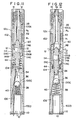
- Figs. 1 to 4 are schematic views showing the outline of the grout injection method according to the present invention.
- a grout injection pipe 4 is held by a chuck 2 and a tip arrangement 6 as will be described in detail referring to Figs. 5 to 13 is connected to a tip end of the injection pipe 4.
- a two-liquids type grout having a short gellation time preferably, 30 seconds or less is supplied. More specifically, a first liquid G and a second liquid G 2 are supplied through a first passage P 1 and a second passage P 2 which are formed in the injection pipe 4, respectively.
- the liquids are combined, contacted and mixed in a mixing chamber and injected from one or more injection orifices 12 into an ambient area to form a columnar sealing mass 14 of the grout which functions as a packer.
- the injecting pipe is raised, as a whole, by given distance or kept in situ without raising the pipe 4 to inject the first liquid G 1 and a second liquid G 2 into the ambient soil while mixing the liquids.
- the gellation time of the grout is preferably 30 seconds or less.
- the liquids injected from the injection orifice or orifices 12 break out the sealing mass 14 and begin to be hardened there. When the liquids are further injected, they, in turn, break out the partially hardened liquids. Thus, a stabilized mass 16 is finally formed around the injection pipe 4. Thereafter, as illustrated in Fig. 4, the injection pipe 4 is raised step by step to repeat the similar operations to form a stabilized mass 16a of a desired length. When the stabilized mass 16a is formed, the injection pipe 4 is removed.
- Figs. 5 and 6 show an operation for feeding boring water and Fig. 6 shows an operation for feeding the grout, i.e., the first and second liquids G 1 and G 2 .
- the tip arrangement 6 is connected to the injection pipe 4 comprised of an outer pipe member 18 and an inner pipe member 20.
- Numerals 22A to 22C each designates a section of an outer pipe member of the tip arrangement 6.
- the lowermost pipe section 22C is provided with a boring bit 24 which functions as a digging edge in the boring operation as shown in Fig. 1.
- Numeral 26 designates an inner pipe member of the tip arrangement having a second passage formed therein which communicates with a passage in the inner pipe member 20 of the injection pipe 4.
- the inner pipe member-26 is disposed in the pipe section 22A concentrically therewith, the gap defined between the pipe member 26 and the pipe section 22A forms the first passage P 1 .
- the inner pipe 26 has, at an -intermediate portion, three holding shoulders 26a projected radially and abuttable against the inner wall of the outer pipe member 22A as illustrated in Fig. 7.
- An annular check valve 28 is disposed at a gap between the upper faces of the shoulders 26a and the lower face of the outer pipe member 18 of the injection pipe 4.
- the check valve 28 has a lug 28a made of a flexible material such as a rubber etc. and in abutment against the outer periphery of the inner pipe 26 so as to partition the first passage P 1 . Therefore, when a fluid is supplied from the above, the lug 28a is bent to disengage from the outer peripheral face of the inner pipe 26, allowing the flow of the fluid. On the other hand, when a fluid pressure acts from the lower side, the lug 28a is pressed hard against the outer periphery of the inner pipe 26 to block the flow of the fluid in the upward direction.
- the sidewall of the pipe section 22A is formed with, for example, 2 to 8 injecting openings 12 which are arranged circumferentially at equal angular spaces.
- the pipe section 22A is screw threadedly engaged with the pipe section 22B through a threaded portion 30.
- the pipe section 22B is, in turn, threadedly coupled to the pipe section 22C through a threaded portion 32.
- the pipe section 22B has, at the upper portion thereof, a guide path 34 which communicates, at a lower portion thereof, with a check valve encasing chamber 38 encasing a ball type check valve 36.
- the check valve 36 is biased towards the base end of the tip arrangement (upwardly as viewed in Fig. 5) by a compression spring 40 resting on the upper face of the pipe section 22C and blocks the guide path 34 when no fluid is applied.
- Numeral 42 is a spool valve which is comprised of a spool portion 42A fitted in a lower portion of the inner pipe 26 and a shutter portion 42B formed integrally with the spool portion 42A and formed as a thin annular member which is fitted in the pipe section 22A and adapted . to close the injection orifices 12.
- the spool valve 42 has a plurality of through holes 42C formed in parallel with the axis of the tip arrangement 6. This spool valve 42 is urged towards the base side by a spring 44 resting against a recess formed on the upper face of the pipe section 22B.
- Numeral 46 designates one or more exit ports which are formed in the sidewall of the inner pipe 26 at a position, in the longitudinal direction, corresponding to the injection orifices 12.
- a first liquid G 1 is pumped into the first passage P 1 and a second liquid G 2 is pumped into the second passage P 2 as illustrated in Fig. 6.
- a pressure acts on the upper face of the spool portion 42A.
- the spool valve 42 is depressed.
- the second liquid G 2 is discharged from the exit port or ports 46 in the horizontal direction.
- the shutter portion 42B is lowered from the injection orifices 12, so that an annular mixing chamber 48 is formed between - the pipe section 22A and the inner pipe 26.
- the second liquid G 2 discharged from the exit port or ports 46 enters the mixing chamber 48.
- a lower portion of the spool portion 42A of the spool valve 42 is inserted into the guide path 34 to block the guide path 34. While the second liquid G 2 is flowing into the annular mixing chamber 48, the first liquid G 1 also enters the mixing chamber 48 from the first passage P 1 .
- the first liquid G 1 is combined, contacted and mixed with the second liquid G 2 substantially at right angles with each other in the annular mixing chamber 48.
- the mixture is then injected through the injection orifices 12 into the ambient soil uniformly in the radial direction.
- the spool valve 42 When the liquid supply to the first passage P and the second passage P 2 is stopped to release the pressure against the spool valve 42, the spool valve 42 is moved upwardly and the outer peripheral wall of the spool portion 42A closes the exit port or ports 46 and simultaneously opens the guide path 34.
- the outer peripheral wall of the shutter portion 42B closes the injection orifices 12 and the check valve 36 closes the guide path 34 which has been opened upon the rising of the spool valve 42.
- the pipe section 22A Since a plurality of injection ports 12 are formed on the pipe section 22A, it is not necessary to rotate the - injection pipe around its axis. Uniform grout injection can be effected around the injection pipe without rotating the injection pipe around its axis as required in the conventional technique which the inventors developed before. Of course, the injection pipe may be rotated in the present invention, too, to obtain a desired effect. Furthermore, since the mixing chamber 48 is formed annular, the first liquid G 1 and the second liquid G 2 are injected from the injection ports 12, 12 ... while being mixed with each other in the chamber uniformly in the circumferential direction. Thus, the combination of the plural formation of the injection orifices on the injection pipe and the annual formation of the mixing chamber 48 enables improved grout injection. In this connection, if the number of the discharge ports 46 is plural, easiness of the mingling and degree of the mixing can be further enhanced.
- the first passage P 1 always communicates with the annular mixing chamber 48, irrespective of the position of the-spool valve 42.
- the first liquid is allowed to pass through the wall surrounding the spool valve, pass through the spool valve and flow out through an exit port formed on another side of the wall only when the second liquid is supplied to the second passage. Therefore, if the first liquid is solidified between the spool valve and the surrounding wall, smooth movement of the spool valve will be prevented.
- the first liquid G 1 is fed directly to the annular mixing chamber 48 without traversing the inner pipe 26 and running around the spool valve 42.
- the first liquid G and the second liquid G 2 are water glass and a hardener, respectively, but may be vice versa.
- a hardener for a water-glass based grouts, many types of hardener may be used.
- an inorganic hardeners such as phosphates, bicarbonates and bisulfates, an organic hardener such as glyoxal and ethylene carbonate . and a combination thereof.
- the spool valve 42 Upon completion of the injection operation, the spool valve 42 is raised immediately, so that the injection orifices 12 are closed by the shutter portion 42A and the guide path 34 is blocked by the check valve 36. Thus, it can surely be prevented that slime from the ambient ground enters the injection pipe which will cause various troubles. Simultaneously, the exit port or ports 46 is closed by the spool portion 42A, so that the mixture of the liquids remaining in the annular mixing chamber 48 is prevented from entering the second passage P 2 through the exit port or ports 46. This arrangement further assures smooth operation of the spool valve 42. The mixture remaining in the mixing chamber 48 is prevented from returning back to the base portion of the grout pipe by the check valve 28. The mixture may be partially solidified in the chamber. However, it has been confirmed-by the experiments conducted by the inventors that if such solidification occurs, the formed mass can easily be discharged through the injection orifices 12 when the injection operation starts again.
- a grout having a gellation time of more than 60 seconds, usually, several minutes to several tenminutes may be supplied only to the first passage P and injected through the nozzle 10, to form a stabilized mass of a slow-curable grout in a sandy subsoil under the sealing mass 14.
- the slow-curable grout forced out of the nozzle 10 is blocked by the previously formed sealing mass 14 and only allowed to spread downwardly or horizontally.
- a slow-curable grout may be injected through the injection orifices 12.
- Figs. 1 to 4 illustrate the injection method in which the injection is carried out by pulling up the grout pipe step by step from its lowermost position
- the injection of the present invention can also be effected by lowering the grout pipe from an initial upper position.
- an exit port or ports 46A may alternatively be located upper than the positions of the injection orifices as illustrated in Fig. 9 to provide perpendicular combining of the liquids. In the latter case, the combining of the liquids Gland G 2 is effected earlier than the embodiment illustrated in Figs. 5 and 6.
- an exit port or ports 46B may be lower than the injection orifices 12, as illustrated in Fig. 10.
- the second liquid G 2 rises in a gap between the spool portion 42A and the shutter portion 42B and is combined and mixed, in counterflow contact, with the first liquid G1 at the inside of the injection orifices 12 and injected through the injection orifices 12.
- FIG. 11 Another form of tip arrangement 60 employable in the present invention is illustrated in Figs. 11 and 12.
- An outer pipe member is comprised of pipe sections 100A to 100D which are connected to each other by threaded portions 102, 104 and 106, and a boring bit is provided at a tip end of the outer pipe member.
- Numeral 112 designates an inner pipe member which differs from the inner pipe member of the tip arrangement illustrated in Figs. 5 and 6, in that the exit port or ports 46, 46A or 46B formed in the sidewall of the inner pipe member 112 are replaced by an exit port 113 which opens at the lower end of the inner pipe member 112 located a bit lower than the injection orifices 12.
- the inner pipe member 112 has a holding shoulder 112a which is held and fixed between a stepped portion formed at a lower end of the pipe section 100A and a stepped portion formed at an upper portion of the pipe section 100B.
- Numeral 114 designates a spool valve with a conical head portion which has a spool portion 114A, a shutter portion 114B radially spaced from the spool portion 114A and through-holes 114C.
- the spool portion 114A and the shutter portion 114B are separate parts and assembled into an integral body by pins etc.
- Other parts or portions are substantially identical with the corresponding parts or portions of the tip arrangement of Figs. 5 and 6 and denoted by the same numerals.
- the second liquid G 2 uniformly enters-the annular mixing chamber 48 and is uniformly combined, contacted and mixed with the first liquid G 1 which is also uniformly fed into the annular mixing chamber 48.
- the lower end of the inner pipe member 112 of the tip arrangement 60 may be located in the base side than the position thereof as illustrated in Figs. 11 and 12, to obtain perpendicular or oblique combination, contact and mixing of the liquids.
- first passage P 1 is provided in a space defined by the outer and inner pipe members in the embodiments as described above, a plurality of first passages P 1 , P 1 ... may alternatively be formed in the pipe section 100B in parallel with the axis of the pipe as illustrated in-Fig. 13, or a plurality of first passages P 1 , P 1 ... may be formed in the inner pipe 26 as illustrated in Fig. 14.
- the grout injection apparatus as described above are suitble especially for the injection of a flash-curable grout having a gellation time of 30 seconds or less, but they may be applied to the injection of a slow-curable grout, too.
- the position of the exit ports may be selected to provide various combining manners according to necessity.
- the exit port is formed at the lower end of the inner pipe member, uniform combining, contact and mixing of the liquids can be obtained in cooperation with the function of the annular mixing chamber.
Abstract
Description
- This invention relates to a grout injection method and apparatus for injecting a grout into the ambient earth.
- In general, a grout injection method has been widely employed for the stabilization of a poor subsoil and developed after many changes. Among these changes, a view point of the penetration of a grout has also been changed. First, it was considered that the penetration of the grout into the soil should be effected slowly to provide effective stabilization of the ground, and a grout having a gellation time of at least 60 seconds, usually, as long as several minutes to several tenminutes was employed. In fact, this method is very effective for the stabilization of a homogeneous sandy soil. However, such a slow-curable grout having a long gellation time does not work effectively in a heterogeneous poor subsoil such as a diluvium deposit or an alluvium deposit, a sandy soil abundantly containing ground water, or a complicated ground condition with cohesive soil mingled. Especially, the slow-curable grout may often be diluted by ground water contained in the soil, during the grout injection operation, to such an extent that the desired compression strength of the stabilized mass cannot be developed, or escaped with the ground water from the area to be treated, or flowed out the surface through a gap between an injection pipe and a wall of a bored hole. Furthermore, the slow-curable grout requires a long hardening time and accordingly requires a long standby time. By these reasons, the slow-curable grout is not always effective and not economical.
- To solve these problems involved in the slow-curable grout, a novel method was developed by the inventors of the present invention around 1975. According to this method, a grout having an extremely short gellation time, i.e., gellation time of several seconds (hereinafter referred to as "instantaneously-curable grout" or "flash-curable grout") is employed, and the grout is injected into the soil, using an injection apparatus having a dual-pipe structure. This novel method has been employed since, prevailing the conventional method as described above. As disclosed in Japanese Patent Publication No. 38448/1980, this method uses an injection apparatus provided with a spool valve which is fitted in an inner pipe member of the double-pipe boring and injecting pipe. The spool valve is normally in an unoperated position, so as to jet a boring water pumped into a first flow passage formed in an outer pipe member, through a nozzle provided at a tip end of the boring and injecting pipe. During the injection operation, - a grout comprised of two liquids which are hardened when combined (hereinafter referred to as "two-liquid type grout") is fed through the first passage and a second passage, respectively, so that the spool valve is pressed down by the liquid fed through the second passage to feed the liquid into a mixing space. The liquid fed through the first passage, is prevented from flowing to the nozzle but allowed to flow, from the first passage, into the mixing chamber. Thus, in this mixing space, the two.liquids are combined, contacted and mixed with each other.
- The inventors of the present invention have confirmed, through results of various workings, that this method can provide effective stabilization of heterogeneous ground in a limited area around an injection orifice of the injection pipe. On the other hand, R. H. Karol reported on the phenomena of penetration of a flash-curable grout in Journal of the Soil Mechanics and Foundations Division of ASCE, April 1961 and January 1968. The results of the workings by the inventors are in accordance with the conclusion derived from the study on the penetration phenomena by R. H. Karol et al.
- However, the method developed by the inventors of the present invention and disclosed in Japanese Patent Publication No. 38448/1980 still has some disadvantages to be improved. First, the mixing chamber should be provided within the injection pipe so as to allow the liquids to be combined, contacted and mixed in the mixing chamber before injection of the grout. Second, the liquids cannot always be mixed sufficiently because the mixing space of the conventional injection pipe is a narrow, restricted space and is located on one side of the injection pipe and, in addition, the liquids are discharged in linear forms to be combined with each other. Third, the injection pipe should be rotated around its axis, during the injection operation, for providing uniform solidification around the injection pipe, because only one injection orifice is provided in the injection pipe. Fourth, the spool valve does not always operate smoothly, because the liquid in the first passage is forced to flow around or through the spool valve.
- The inventors have made intensive and extensive study with a view to solving the problems as described above and found that (1) the structure can be simplified and the operation of the spool valve can be more smooth by an arrangement in which the liquid in the first passage communicates directly with the mixing chamber instead of introducing the liquid into the mixing chamber from a by-pass formed between the outer and inner pipe members, traversing the spool valve, and (2.) a plurality of injection orifices can be provided by providing an annular mixing chamber, to enable uniform injection in the limited area around the injection pipe, without rotating the injection pipe around its axis. On the basis of these findings, the inventors have made the present invention.
- In accordance with a first aspect of the present invention, there is. provided a grout injection method for injecting a grout composed of a first liquid and a second liquid and curable when the liquids are combined, which. comprises: feeding said first liquid through a peripheral portion of an injection pipe comprised of an inner pipe member and an outer pipe member having one or more injection orifices formed in the sidewall thereof, in parallel with the axis of said injection pipe, to introduce said first liquid into an annular mixing chamber; feeding said second liquid to said inner pipe member to depress, by a.pressure of the liquid, a spool valve fitted in said inner pipe member, so as to introduce said second liquid into said annular mixing chamber, combining, contacting and mixing the liquids in said annular mixing chamber; and injecting the mixture of the liquids into the ambient soil through said one or more injection orifices.
- In accordance with a second aspect of the present invention, there is provided a grout injection apparatus comprising an injection pipe which comprises: an inner pipe member; an outer pipe member having one or more injection orifices formed in the sidewall thereof; a first passage formed at a peripheral portion of said injection pipe in parallel with an axis of the pipe; a second passage formed in said inner pipe member; a spool valve fitted in said inner pipe member and biased towards the base side of said injection pipe; one or more exit ports which are formed in a sidewall of said inner pipe member and adapted to be closed normally and communicate with said second passage when said spool valve is displaced towards the tip side of said injection pipe, against a biasing force thereof, upon application of a fluid pressure upon said second passage; and an annular mixing chamber formed between said inner and outer pipe members so as to communicate with said one or more injection orifices and said one or more exit ports.
- In accordance with a third aspect of the present invention, there is provided a grout injection apparatus comprising an injection pipe which comprises: an inner pipe member; an outer pipe member having one or more injection orifices formed in a sidewall thereof; a first passage formed at a peripheral portion of said injection pipe in parallel with an axis of said pipe; a second passage - formed in said inner pipe member; a spool valve inserted in said inner pipe member at a lower portion thereof and biased towards the base end of said injection pipe; said spool valve normally closing an exit port formed at a lower end of said inner pipe member and disengaging from said lower end of said inner pipe member to open said exit port when displaced towards the tip'-end of said injection pipe upon application of a fluid pressure onto said second passage; and an annular mixing chamber formed between said outer pipe member and said inner pipe member to communicate with said one or more injection or.ifices and said exit port.
- The invention will be better understood from the description taken in connection with the accompanying drawings in which:
- Figs. 1 to 4 are sectional views showing the sequence of the working steps of the present invention;
- Fig. 5 is a longitudinal cross section of a tip arrangement of the grout injecting apparatus according to the present invention, shown in a position for feeding boring water;
- Fig. 6 is a similar longitudinal cross section of the tip arrangement, shown in a position for injecting a grout;
- Fig. 7 is a transverse cross section taken along a line 7-7 of Fig. 5;
- Fig. 8 is a transverse cross section taken along a line 8-8 of Fig. 5;
- Figs. 9 and 10 are longitudinal cross sections of modifications of the tip arrangement shown in Fig. 5, respectively;
- Fig. 11 is a longitudinal cross section of another form of the tip arrangement according to the present invention, shown in a position for feeding boring water;
- Fig. 12 is a similar longitudinal cross section of the tip arrangement, shown in a position for injecting a grout; and
- Figs. 13 and 14 are transverse cross sections each showing a modified formation of a first passage.
- Referring now to the drawings, there are illustrated preferred embodiments of the present invention. Figs. 1 to 4 are schematic views showing the outline of the grout injection method according to the present invention. A
grout injection pipe 4 is held by achuck 2 and atip arrangement 6 as will be described in detail referring to Figs. 5 to 13 is connected to a tip end of theinjection pipe 4. - In this arrangement, boring water is first supplied by a grout injecting pump (not shown) to the swivel 8 through a hose to jet the boring water W from a
nozzle 10 as illustrated in Fig. 1. At the same time, theinjection pipe 4 and thetip arrangement 6 are driven downwardly while being rotated around the axis as shown by an arrow in Fig. 1. As the boring proceeds, pipe sections are connected to theinjection pipe 4 one after another. - When the
injection pipe 4 reaches a predetermined depth, a two-liquids type grout having a short gellation time, preferably, 30 seconds or less is supplied. More specifically, a first liquid G and a second liquid G2 are supplied through a first passage P1 and a second passage P2 which are formed in theinjection pipe 4, respectively. The liquids are combined, contacted and mixed in a mixing chamber and injected from one ormore injection orifices 12 into an ambient area to form a columnar sealingmass 14 of the grout which functions as a packer. Then, the injecting pipe is raised, as a whole, by given distance or kept in situ without raising thepipe 4 to inject the first liquid G1 and a second liquid G2 into the ambient soil while mixing the liquids. The gellation time of the grout is preferably 30 seconds or less. The liquids injected from the injection orifice ororifices 12 break out the sealingmass 14 and begin to be hardened there. When the liquids are further injected, they, in turn, break out the partially hardened liquids. Thus, a stabilizedmass 16 is finally formed around theinjection pipe 4. Thereafter, as illustrated in Fig. 4, theinjection pipe 4 is raised step by step to repeat the similar operations to form a stabilizedmass 16a of a desired length. When the stabilizedmass 16a is formed, theinjection pipe 4 is removed. - The detail of one form of the
tip arrangement 6 is illustrated in Figs. 5 and 6. Fig. 5 shows an operation for feeding boring water and Fig. 6 shows an operation for feeding the grout, i.e., the first and second liquids G1 and G 2. - The
tip arrangement 6 is connected to theinjection pipe 4 comprised of anouter pipe member 18 and aninner pipe member 20.Numerals 22A to 22C each designates a section of an outer pipe member of thetip arrangement 6. Thelowermost pipe section 22C is provided with aboring bit 24 which functions as a digging edge in the boring operation as shown in Fig. 1. Numeral 26 designates an inner pipe member of the tip arrangement having a second passage formed therein which communicates with a passage in theinner pipe member 20 of theinjection pipe 4. The inner pipe member-26 is disposed in thepipe section 22A concentrically therewith, the gap defined between thepipe member 26 and thepipe section 22A forms the first passage P1. Theinner pipe 26 has, at an -intermediate portion, three holdingshoulders 26a projected radially and abuttable against the inner wall of theouter pipe member 22A as illustrated in Fig. 7. Anannular check valve 28 is disposed at a gap between the upper faces of theshoulders 26a and the lower face of theouter pipe member 18 of theinjection pipe 4. Thecheck valve 28 has alug 28a made of a flexible material such as a rubber etc. and in abutment against the outer periphery of theinner pipe 26 so as to partition the first passage P1. Therefore, when a fluid is supplied from the above, thelug 28a is bent to disengage from the outer peripheral face of theinner pipe 26, allowing the flow of the fluid. On the other hand, when a fluid pressure acts from the lower side, thelug 28a is pressed hard against the outer periphery of theinner pipe 26 to block the flow of the fluid in the upward direction. - The sidewall of the
pipe section 22A is formed with, for example, 2 to 8injecting openings 12 which are arranged circumferentially at equal angular spaces. Thepipe section 22A is screw threadedly engaged with thepipe section 22B through a threadedportion 30. Similarly, thepipe section 22B is, in turn, threadedly coupled to thepipe section 22C through a threadedportion 32. Thepipe section 22B has, at the upper portion thereof, aguide path 34 which communicates, at a lower portion thereof, with a checkvalve encasing chamber 38 encasing a balltype check valve 36. Thecheck valve 36 is biased towards the base end of the tip arrangement (upwardly as viewed in Fig. 5) by acompression spring 40 resting on the upper face of thepipe section 22C and blocks theguide path 34 when no fluid is applied. -
Numeral 42 is a spool valve which is comprised of aspool portion 42A fitted in a lower portion of theinner pipe 26 and ashutter portion 42B formed integrally with thespool portion 42A and formed as a thin annular member which is fitted in thepipe section 22A and adapted . to close the injection orifices 12. Thespool valve 42 has a plurality of throughholes 42C formed in parallel with the axis of thetip arrangement 6. Thisspool valve 42 is urged towards the base side by aspring 44 resting against a recess formed on the upper face of thepipe section 22B.Numeral 46 designates one or more exit ports which are formed in the sidewall of theinner pipe 26 at a position, in the longitudinal direction, corresponding to the injection orifices 12. - In the so formed
tip arrangement 6, when boring water W is fed into the gap between theouter pipe 18 and theinner pipe 20 as illustrated in Fig. 5, the boring water W flows into the first passage P1 while bending thelug 28a, then further flows to theguide path 34 through the annular gap between thespool portion 42A andshutter portion 42B of thespool valve 42 and through the throughholes 42C, to depress thecheck valve 36 against the action of thespring 40. The boring water W is, then, jetted from thenozzle 10 through thepipe section 22C. Thus, boring can be effected as described above referring to Fig. 1. - On the other hand, to form the sealing
mass 14 or the stabilizedmass 16 as illustrated in Fig. 2 or in Fig. 3, a first liquid G1 is pumped into the first passage P1 and a second liquid G2 is pumped into the second passage P2 as illustrated in Fig. 6. As the second liquid G2 is being pumped, a pressure acts on the upper face of thespool portion 42A. When the pressure prevails over the urging force of thespring 44, thespool valve 42 is depressed. As a result, the second liquid G2 is discharged from the exit port orports 46 in the horizontal direction. In accordance with the depression of thespool valve 42, theshutter portion 42B is lowered from theinjection orifices 12, so that anannular mixing chamber 48 is formed between - thepipe section 22A and theinner pipe 26. The second liquid G2 discharged from the exit port orports 46 enters the mixingchamber 48. On the other hand, as a result of the depression of thespool valve 42, a lower portion of thespool portion 42A of thespool valve 42 is inserted into theguide path 34 to block theguide path 34. While the second liquid G2 is flowing into theannular mixing chamber 48, the first liquid G1 also enters the mixingchamber 48 from the first passage P1. At this time, since theguide path 34 has already been closed by thespool portion 42A, the first liquid G1 is combined, contacted and mixed with the second liquid G2 substantially at right angles with each other in theannular mixing chamber 48. The mixture is then injected through theinjection orifices 12 into the ambient soil uniformly in the radial direction. - When the liquid supply to the first passage P and the second passage P2 is stopped to release the pressure against the
spool valve 42, thespool valve 42 is moved upwardly and the outer peripheral wall of thespool portion 42A closes the exit port orports 46 and simultaneously opens theguide path 34. The outer peripheral wall of theshutter portion 42B closes theinjection orifices 12 and thecheck valve 36 closes theguide path 34 which has been opened upon the rising of thespool valve 42. - Since a plurality of
injection ports 12 are formed on thepipe section 22A, it is not necessary to rotate the - injection pipe around its axis. Uniform grout injection can be effected around the injection pipe without rotating the injection pipe around its axis as required in the conventional technique which the inventors developed before. Of course, the injection pipe may be rotated in the present invention, too, to obtain a desired effect. Furthermore, since the mixingchamber 48 is formed annular, the first liquid G1 and the second liquid G2 are injected from theinjection ports chamber 48 enables improved grout injection. In this connection, if the number of thedischarge ports 46 is plural, easiness of the mingling and degree of the mixing can be further enhanced. - The first passage P1 always communicates with the
annular mixing chamber 48, irrespective of the position of the-spool valve 42. By contrast, in the conventional grout apparatus as described in the aforesaid Japanese Patent Publication 38448/1980, the first liquid is allowed to pass through the wall surrounding the spool valve, pass through the spool valve and flow out through an exit port formed on another side of the wall only when the second liquid is supplied to the second passage. Therefore, if the first liquid is solidified between the spool valve and the surrounding wall, smooth movement of the spool valve will be prevented. In the embodiment of the present invention as described above, however, the first liquid G1 is fed directly to theannular mixing chamber 48 without traversing theinner pipe 26 and running around thespool valve 42. With this arrangement, smooth operation of thespool valve 42 is assured even after a long use of the apparatus. The first liquid G and the second liquid G2 are water glass and a hardener, respectively, but may be vice versa. For a water-glass based grouts, many types of hardener may be used. As the hardener employable in the present invention, there can be mentioned an inorganic hardeners such as phosphates, bicarbonates and bisulfates, an organic hardener such as glyoxal and ethylene carbonate . and a combination thereof. - Upon completion of the injection operation, the
spool valve 42 is raised immediately, so that theinjection orifices 12 are closed by theshutter portion 42A and theguide path 34 is blocked by thecheck valve 36. Thus, it can surely be prevented that slime from the ambient ground enters the injection pipe which will cause various troubles. Simultaneously, the exit port orports 46 is closed by thespool portion 42A, so that the mixture of the liquids remaining in theannular mixing chamber 48 is prevented from entering the second passage P2 through the exit port orports 46. This arrangement further assures smooth operation of thespool valve 42. The mixture remaining in the mixingchamber 48 is prevented from returning back to the base portion of the grout pipe by thecheck valve 28. The mixture may be partially solidified in the chamber. However, it has been confirmed-by the experiments conducted by the inventors that if such solidification occurs, the formed mass can easily be discharged through theinjection orifices 12 when the injection operation starts again. - In general, it is considered that when the mixture of the first liquid G1 and the second liquid G2 having a short gellation time is left in the
annular mixing chamber 48 after the supply of the liquids G1, G2 has been stopped due to completion or interruption of the injection operation, the mixture is solidified there, blocking the rising of theshutter portion 42B of thespool valve 42. However, since there is a time lag between the times the first and the second liquid G and G2 are actually stopped, the ratio of the first liquid G1 to the second liquid G2 which are contained in the mixture remaining in the mixingchamber 48 gets out of the range suitable for solidification, and the mixture can not completely be solidified. Therefore, thespool valve 42 can smoothly be restored to its original position, overcoming the solidifying force of the mixture, with the aid of thespring 44. - In this connection, it is to be noted that after the step of Fig. 2, a grout having a gellation time of more than 60 seconds, usually, several minutes to several tenminutes may be supplied only to the first passage P and injected through the
nozzle 10, to form a stabilized mass of a slow-curable grout in a sandy subsoil under the sealingmass 14. In this case, the slow-curable grout forced out of thenozzle 10 is blocked by the previously formed sealingmass 14 and only allowed to spread downwardly or horizontally. Alternatively, after the injection of the flash-curable grout, a slow-curable grout may be injected through the injection orifices 12. Although Figs. 1 to 4 illustrate the injection method in which the injection is carried out by pulling up the grout pipe step by step from its lowermost position, the injection of the present invention can also be effected by lowering the grout pipe from an initial upper position. - Although the positions of the
injection orifices 12 in the longitudinal direction of the injecting pipe are the same as those of the exit port orports 46 in the foregoing embodiment, so as to combine the liquids G1 and G2 perpendicularly to each other, an exit port orports 46A may alternatively be located upper than the positions of the injection orifices as illustrated in Fig. 9 to provide perpendicular combining of the liquids. In the latter case, the combining of the liquids Gland G2 is effected earlier than the embodiment illustrated in Figs. 5 and 6. Alternatively, an exit port orports 46B may be lower than theinjection orifices 12, as illustrated in Fig. 10. In this case, the second liquid G2 rises in a gap between thespool portion 42A and theshutter portion 42B and is combined and mixed, in counterflow contact, with the first liquid G1 at the inside of theinjection orifices 12 and injected through the injection orifices 12. - Another form of
tip arrangement 60 employable in the present invention is illustrated in Figs. 11 and 12. An outer pipe member is comprised ofpipe sections 100A to 100D which are connected to each other by threadedportions Numeral 112 designates an inner pipe member which differs from the inner pipe member of the tip arrangement illustrated in Figs. 5 and 6, in that the exit port orports inner pipe member 112 are replaced by anexit port 113 which opens at the lower end of theinner pipe member 112 located a bit lower than the injection orifices 12. Theinner pipe member 112 has a holdingshoulder 112a which is held and fixed between a stepped portion formed at a lower end of thepipe section 100A and a stepped portion formed at an upper portion of thepipe section 100B.Numeral 114 designates a spool valve with a conical head portion which has aspool portion 114A, ashutter portion 114B radially spaced from thespool portion 114A and through-holes 114C. In the embodiment as illustrated, thespool portion 114A and theshutter portion 114B are separate parts and assembled into an integral body by pins etc. Other parts or portions are substantially identical with the corresponding parts or portions of the tip arrangement of Figs. 5 and 6 and denoted by the same numerals. - In operation, when the boring water W is supplied as illustrated in Fig. 11, the boring water W is jetted from the
nozzle 10 as indicated by arrows. When the first liquid G1 and the second liquid G2 are supplied to the first passage P1 and the second passage P2, respectively, as illustrated in Fig. 12, the first liquid G flows down into theannular mixing chamber 48 through the first passage P1. The second liquid G2 depresses thespool valve 114 against the biasing force of thespring 44. As a result, the second liquid G2 passes through a gap formed between the lower end periphery of theinner pipe member 112 and the conical face of the head portion of thespool portion 114A and uniformly discharged obliquely downwardly into theannular mixing chamber 48. The second liquid G2, then, turns upwardly to be combined, contacted and mixed, in a counterflow manner, with the first liquid G which flows downwardly, and the mixture is injected through the injection orifices into the ambient earth. - In this embodiment, the second liquid G2 uniformly enters-the
annular mixing chamber 48 and is uniformly combined, contacted and mixed with the first liquid G1 which is also uniformly fed into theannular mixing chamber 48. - The lower end of the
inner pipe member 112 of thetip arrangement 60 may be located in the base side than the position thereof as illustrated in Figs. 11 and 12, to obtain perpendicular or oblique combination, contact and mixing of the liquids. - Although the first passage P1 is provided in a space defined by the outer and inner pipe members in the embodiments as described above, a plurality of first passages P1, P1 ... may alternatively be formed in the
pipe section 100B in parallel with the axis of the pipe as illustrated in-Fig. 13, or a plurality of first passages P1, P1 ... may be formed in theinner pipe 26 as illustrated in Fig. 14. - The grout injection apparatus as described above are suitble especially for the injection of a flash-curable grout having a gellation time of 30 seconds or less, but they may be applied to the injection of a slow-curable grout, too.
- As described above, according to the first embodiment of the present invention, the mixing chamber is shaped in an annular form, so that uniform combining, contact and mixing of the liquids can be effected. And, a plurality of injection orifices are provided so that uniform injection is effected without rotating the injection pipe.
- According to the second embodiment, the position of the exit ports may be selected to provide various combining manners according to necessity.
- According to the third embodiment, since the exit port is formed at the lower end of the inner pipe member, uniform combining, contact and mixing of the liquids can be obtained in cooperation with the function of the annular mixing chamber.
Claims (13)
Applications Claiming Priority (2)
| Application Number | Priority Date | Filing Date | Title |
|---|---|---|---|
| JP204047/81 | 1981-12-16 | ||
| JP56204047A JPS58106013A (en) | 1981-12-16 | 1981-12-16 | Method and apparatus for grout injection work |
Publications (3)
| Publication Number | Publication Date |
|---|---|
| EP0081620A2 true EP0081620A2 (en) | 1983-06-22 |
| EP0081620A3 EP0081620A3 (en) | 1983-07-20 |
| EP0081620B1 EP0081620B1 (en) | 1986-05-07 |
Family
ID=16483867
Family Applications (1)
| Application Number | Title | Priority Date | Filing Date |
|---|---|---|---|
| EP82100809A Expired EP0081620B1 (en) | 1981-12-16 | 1982-02-04 | Grout injection method and apparatus |
Country Status (4)
| Country | Link |
|---|---|
| US (1) | US4449856A (en) |
| EP (1) | EP0081620B1 (en) |
| JP (1) | JPS58106013A (en) |
| DE (1) | DE3270930D1 (en) |
Cited By (5)
| Publication number | Priority date | Publication date | Assignee | Title |
|---|---|---|---|---|
| DE3514522A1 (en) * | 1984-05-09 | 1985-11-14 | N.I.T. Co., Ltd., Machida, Tokio/Tokyo | METHOD AND DEVICE FOR FORMING A GROUND FASTENING CONSTRUCTION |
| EP0202438A1 (en) * | 1985-05-09 | 1986-11-26 | Bauer Spezialtiefbau GmbH | Apparatus for consolidating and/or sealing a predetermined area in the soil |
| EP0286234A2 (en) * | 1987-04-10 | 1988-10-12 | Shouhei Chida | Liquid chemical grouting apparatus and valve switching arrangement in conduit system for supplying liquid chemicals to the apparatus |
| EP0589243A2 (en) * | 1992-08-31 | 1994-03-30 | McCABE BROTHERS, Inc. | Long hole chemical grout injector system |
| JP2012167497A (en) * | 2011-02-15 | 2012-09-06 | Okumura Corp | Chemical injection device |
Families Citing this family (33)
| Publication number | Priority date | Publication date | Assignee | Title |
|---|---|---|---|---|
| JPS6117628A (en) * | 1984-06-30 | 1986-01-25 | Chem Kurauto Kk | Chemical grout injector |
| US4630972A (en) * | 1984-10-29 | 1986-12-23 | Utilitech, Incorporated | Impulse injector apparatus |
| JP2630587B2 (en) * | 1986-03-04 | 1997-07-16 | 日東化学工業株式会社 | Grout injection method |
| US4900196A (en) * | 1987-11-20 | 1990-02-13 | Iit Research Institute | Confinement in porous material by driving out water and substituting sealant |
| US5013185A (en) * | 1988-03-23 | 1991-05-07 | Osamu Taki | Multi-shaft auger apparatus and process for fixation of soils containing toxic wastes |
| US4886400A (en) * | 1988-03-23 | 1989-12-12 | S.M.W. Seiko, Inc. | Side cutting blades for multi-shaft auger system and improved soil mixing wall formation process |
| US4906142A (en) * | 1988-03-23 | 1990-03-06 | S.M.W. Seiko, Inc. | Side cutting blades for multi-shaft auger system and improved soil mixing wall formation process |
| US5118223A (en) * | 1988-03-23 | 1992-06-02 | Osamu Taki | Multi-shaft auger apparatus and process for forming soilcrete columns and walls and grids in situ in soil |
| US4909675A (en) * | 1988-08-24 | 1990-03-20 | Osamu Taki | In situ reinforced structural diaphragm walls and methods of manufacturing |
| JPH06104967B2 (en) * | 1989-01-27 | 1994-12-21 | 鹿島建設株式会社 | Large diameter ground improvement method |
| DE3936040A1 (en) * | 1989-09-07 | 1991-05-29 | Fischer Artur Werke Gmbh | INJECTION PACKER FOR INJECTING RESIN IN CONCRETE Cracks |
| US5343968A (en) * | 1991-04-17 | 1994-09-06 | The United States Of America As Represented By The United States Department Of Energy | Downhole material injector for lost circulation control |
| US6585455B1 (en) | 1992-08-18 | 2003-07-01 | Shell Oil Company | Rocker arm marine tensioning system |
| JP2729749B2 (en) * | 1993-06-22 | 1998-03-18 | 志朗 中嶋 | Omnidirectional ground improvement body construction method and its device |
| US5409071A (en) * | 1994-05-23 | 1995-04-25 | Shell Oil Company | Method to cement a wellbore |
| ATE249553T1 (en) * | 1997-07-14 | 2003-09-15 | Kyokado Eng Co | METHOD AND DEVICE WITH A MULTIPLE INJECTION OPENINGS FOR INTRODUCING AN AUXILIARY SUBSTANCE INTO SOFT SUBSTRATE |
| US6257803B1 (en) * | 1998-07-23 | 2001-07-10 | Mccabe Howard Wendell | Three component chemical grout injector |
| KR100467863B1 (en) * | 2002-09-05 | 2005-01-26 | 주식회사 우정엔지니어링건축사사무소 | Direct-boring grouting apparatus |
| KR20040026494A (en) * | 2002-09-25 | 2004-03-31 | 윤인태 | Front Device for Grouting |
| KR100488593B1 (en) * | 2002-10-17 | 2005-05-12 | (주)진양비지엠텍 | grouting apparatus |
| US6863475B2 (en) * | 2003-04-30 | 2005-03-08 | Shell Oil Company | Apparatus for injecting fluids |
| US6796741B1 (en) | 2003-04-30 | 2004-09-28 | Shell Oil Company | In-situ bioremediation process and apparatus |
| KR200339990Y1 (en) * | 2003-10-07 | 2004-01-28 | 김영용 | The multi pipe chemical injection equipment for grouting |
| US7281576B2 (en) * | 2004-03-12 | 2007-10-16 | Halliburton Energy Services, Inc. | Apparatus and methods for sealing voids in a subterranean formation |
| KR100655850B1 (en) * | 2005-09-27 | 2006-12-13 | 황병권 | the packer for repairing crack in concrete body |
| KR200438510Y1 (en) * | 2006-12-22 | 2008-02-21 | (주)더페이스샵코리아 | Compact case |
| US20090068352A1 (en) * | 2007-09-10 | 2009-03-12 | Michael Gibson | Flood Temporary Relief System and Method |
| ITTO20080335A1 (en) * | 2008-05-06 | 2009-11-07 | Trevi Spa | HEAD OF INJECTION FOR THE EXECUTION OF JET GROUTING TECHNIQUES |
| SE534066C2 (en) * | 2009-02-09 | 2011-04-19 | Wassara Ab | Device for lowering drills for use in soil reinforcement |
| MX354211B (en) | 2012-11-05 | 2018-02-19 | Geopier Found Co Inc | Soil densification system and method. |
| US9909277B2 (en) * | 2015-02-12 | 2018-03-06 | Silar Services Inc. | In situ waste remediation methods and systems |
| CN110797500A (en) * | 2018-08-02 | 2020-02-14 | 宁波商路数据技术有限公司 | Centrifugal liquid injection method and centrifugal liquid injection equipment thereof |
| EP3816394B1 (en) * | 2019-10-30 | 2023-11-29 | L&T Mining Solutions Oy | A method and a drill bit for sealing a blasthole wall |
Citations (4)
| Publication number | Priority date | Publication date | Assignee | Title |
|---|---|---|---|---|
| US2682388A (en) * | 1953-02-13 | 1954-06-29 | Winter Weiss Co | Drill for forming solidified core piles |
| DE2935126A1 (en) * | 1978-08-30 | 1980-03-13 | Sato Kogyo | METHOD FOR INJECTING MORTAR SLUDGE IN EARTH |
| GB2063337A (en) * | 1979-11-08 | 1981-06-03 | Nitto Chemical Industry Co Ltd | Method for injecting sodium silicate grout into ground |
| US4286900A (en) * | 1979-10-24 | 1981-09-01 | Tokyo Chika Koji Kabushiki Kaisha | Injection device of chemical fluids for improvements of the ground |
Family Cites Families (5)
| Publication number | Priority date | Publication date | Assignee | Title |
|---|---|---|---|---|
| JPS54152310A (en) * | 1978-05-22 | 1979-11-30 | Toa Gurauto Kougiyou Kk | Strainer injection device of chemicals for stabilizing ground |
| JPS55114706A (en) * | 1979-02-23 | 1980-09-04 | Yamaguchi Kikai Kogyo Kk | Grouting method and apparatus thereof |
| JPS5830446B2 (en) * | 1979-03-05 | 1983-06-29 | 東亜グラウト工業株式会社 | Strainer injection device for soil stabilization chemicals |
| JPS55161111A (en) * | 1979-06-05 | 1980-12-15 | Yamaguchi Kikai Kogyo Kk | Method and apparatus for injecting chemical agent |
| JPS569517A (en) * | 1979-07-04 | 1981-01-31 | Kenji Shimizu | Apparatus for injecting ground stabilizing liquid into strainer |
-
1981
- 1981-12-16 JP JP56204047A patent/JPS58106013A/en active Granted
-
1982
- 1982-02-03 US US06/345,445 patent/US4449856A/en not_active Expired - Lifetime
- 1982-02-04 DE DE8282100809T patent/DE3270930D1/en not_active Expired
- 1982-02-04 EP EP82100809A patent/EP0081620B1/en not_active Expired
Patent Citations (4)
| Publication number | Priority date | Publication date | Assignee | Title |
|---|---|---|---|---|
| US2682388A (en) * | 1953-02-13 | 1954-06-29 | Winter Weiss Co | Drill for forming solidified core piles |
| DE2935126A1 (en) * | 1978-08-30 | 1980-03-13 | Sato Kogyo | METHOD FOR INJECTING MORTAR SLUDGE IN EARTH |
| US4286900A (en) * | 1979-10-24 | 1981-09-01 | Tokyo Chika Koji Kabushiki Kaisha | Injection device of chemical fluids for improvements of the ground |
| GB2063337A (en) * | 1979-11-08 | 1981-06-03 | Nitto Chemical Industry Co Ltd | Method for injecting sodium silicate grout into ground |
Non-Patent Citations (1)
| Title |
|---|
| JP Patent Publication 38448/1980 * |
Cited By (7)
| Publication number | Priority date | Publication date | Assignee | Title |
|---|---|---|---|---|
| DE3514522A1 (en) * | 1984-05-09 | 1985-11-14 | N.I.T. Co., Ltd., Machida, Tokio/Tokyo | METHOD AND DEVICE FOR FORMING A GROUND FASTENING CONSTRUCTION |
| EP0202438A1 (en) * | 1985-05-09 | 1986-11-26 | Bauer Spezialtiefbau GmbH | Apparatus for consolidating and/or sealing a predetermined area in the soil |
| EP0286234A2 (en) * | 1987-04-10 | 1988-10-12 | Shouhei Chida | Liquid chemical grouting apparatus and valve switching arrangement in conduit system for supplying liquid chemicals to the apparatus |
| EP0286234A3 (en) * | 1987-04-10 | 1988-11-30 | Shouhei Chida | Liquid chemical grouting apparatus and valve switching arrangement in conduit system for supplying liquid chemicals to the apparatus |
| EP0589243A2 (en) * | 1992-08-31 | 1994-03-30 | McCABE BROTHERS, Inc. | Long hole chemical grout injector system |
| EP0589243A3 (en) * | 1992-08-31 | 1995-05-17 | Mccabe Brothers Inc | Long hole chemical grout injector system. |
| JP2012167497A (en) * | 2011-02-15 | 2012-09-06 | Okumura Corp | Chemical injection device |
Also Published As
| Publication number | Publication date |
|---|---|
| JPS58106013A (en) | 1983-06-24 |
| EP0081620B1 (en) | 1986-05-07 |
| DE3270930D1 (en) | 1986-06-12 |
| JPH0160614B2 (en) | 1989-12-25 |
| EP0081620A3 (en) | 1983-07-20 |
| US4449856A (en) | 1984-05-22 |
Similar Documents
| Publication | Publication Date | Title |
|---|---|---|
| EP0081620B1 (en) | Grout injection method and apparatus | |
| JP2004270444A (en) | Soft ground improving device | |
| KR20050090306A (en) | An apparatus for mix-processing high pressure jet injection | |
| JP3940735B2 (en) | Earth retaining method | |
| JPH10306435A (en) | Grouting and hardening method and grouting equipment | |
| JPS5862212A (en) | Grout injector | |
| KR101976614B1 (en) | Grout injection device with anti-backflow valve | |
| KR102297431B1 (en) | High pressure grouting injection equipment | |
| KR200255662Y1 (en) | Direct-boring grouting apparatus | |
| JP3247516B2 (en) | Injection pipe for ground improvement | |
| JP2003213664A (en) | Chemical injection method, chemical injection device and soil purification method | |
| JP4583263B2 (en) | Chemical injection pipe and chemical injection method | |
| JP2946061B2 (en) | Compound grouting method and equipment used for it | |
| JPH05255926A (en) | Chemical grouting method and device therefor | |
| JPS6253649B2 (en) | ||
| JP2823383B2 (en) | Ground improvement material injection method | |
| JP2554317B2 (en) | Drilling method on soft ground and apparatus used therefor | |
| JP2005048497A (en) | Method for inhibiting precipitation of efflorescence | |
| JP2586984B2 (en) | Ground injection method and injection pipe | |
| KR860001186B1 (en) | Apparatus for hardening the soft soil | |
| JPS58168716A (en) | Structure of drilling and grout injection tube | |
| JPS5858314A (en) | Grout injector | |
| JPH101938A (en) | Chemical injection device | |
| JPS63184608A (en) | Chemical grouting device | |
| JP2698762B2 (en) | Drilling bit and drilling method using the bit |
Legal Events
| Date | Code | Title | Description |
|---|---|---|---|
| PUAI | Public reference made under article 153(3) epc to a published international application that has entered the european phase |
Free format text: ORIGINAL CODE: 0009012 |
|
| PUAL | Search report despatched |
Free format text: ORIGINAL CODE: 0009013 |
|
| AK | Designated contracting states |
Designated state(s): DE FR GB IT SE |
|
| AK | Designated contracting states |
Designated state(s): DE FR GB IT SE |
|
| 17P | Request for examination filed |
Effective date: 19831207 |
|
| GRAA | (expected) grant |
Free format text: ORIGINAL CODE: 0009210 |
|
| AK | Designated contracting states |
Kind code of ref document: B1 Designated state(s): DE FR GB IT SE |
|
| REF | Corresponds to: |
Ref document number: 3270930 Country of ref document: DE Date of ref document: 19860612 |
|
| ITF | It: translation for a ep patent filed |
Owner name: JACOBACCI & PERANI S.P.A. |
|
| ET | Fr: translation filed | ||
| PLBE | No opposition filed within time limit |
Free format text: ORIGINAL CODE: 0009261 |
|
| STAA | Information on the status of an ep patent application or granted ep patent |
Free format text: STATUS: NO OPPOSITION FILED WITHIN TIME LIMIT |
|
| 26N | No opposition filed | ||
| ITTA | It: last paid annual fee | ||
| PGFP | Annual fee paid to national office [announced via postgrant information from national office to epo] |
Ref country code: GB Payment date: 19950125 Year of fee payment: 14 |
|
| PGFP | Annual fee paid to national office [announced via postgrant information from national office to epo] |
Ref country code: SE Payment date: 19950127 Year of fee payment: 14 Ref country code: FR Payment date: 19950127 Year of fee payment: 14 |
|
| EAL | Se: european patent in force in sweden |
Ref document number: 82100809.1 |
|
| PGFP | Annual fee paid to national office [announced via postgrant information from national office to epo] |
Ref country code: DE Payment date: 19950227 Year of fee payment: 14 |
|
| PG25 | Lapsed in a contracting state [announced via postgrant information from national office to epo] |
Ref country code: GB Effective date: 19960204 |
|
| PG25 | Lapsed in a contracting state [announced via postgrant information from national office to epo] |
Ref country code: SE Effective date: 19960205 |
|
| GBPC | Gb: european patent ceased through non-payment of renewal fee |
Effective date: 19960204 |
|
| PG25 | Lapsed in a contracting state [announced via postgrant information from national office to epo] |
Ref country code: FR Effective date: 19961031 |
|
| PG25 | Lapsed in a contracting state [announced via postgrant information from national office to epo] |
Ref country code: DE Effective date: 19961101 |
|
| REG | Reference to a national code |
Ref country code: FR Ref legal event code: ST |