EP0081380B1 - Verfahren und Vorrichtung zur Mahlen von Pulpholz und Holzspanen durch Fliehkraft - Google Patents
Verfahren und Vorrichtung zur Mahlen von Pulpholz und Holzspanen durch Fliehkraft Download PDFInfo
- Publication number
- EP0081380B1 EP0081380B1 EP82306519A EP82306519A EP0081380B1 EP 0081380 B1 EP0081380 B1 EP 0081380B1 EP 82306519 A EP82306519 A EP 82306519A EP 82306519 A EP82306519 A EP 82306519A EP 0081380 B1 EP0081380 B1 EP 0081380B1
- Authority
- EP
- European Patent Office
- Prior art keywords
- grinding surface
- rotor
- water
- grinding
- centrifugal
- Prior art date
- Legal status (The legal status is an assumption and is not a legal conclusion. Google has not performed a legal analysis and makes no representation as to the accuracy of the status listed.)
- Expired
Links
- 238000000034 method Methods 0.000 title claims description 24
- 239000002023 wood Substances 0.000 title claims description 21
- XLYOFNOQVPJJNP-UHFFFAOYSA-N water Substances O XLYOFNOQVPJJNP-UHFFFAOYSA-N 0.000 claims description 42
- 230000037361 pathway Effects 0.000 claims description 17
- 239000000463 material Substances 0.000 claims description 14
- 230000008569 process Effects 0.000 claims description 9
- 230000000694 effects Effects 0.000 claims description 8
- 239000002002 slurry Substances 0.000 claims description 8
- 238000005507 spraying Methods 0.000 claims description 4
- 238000009835 boiling Methods 0.000 claims description 3
- 229920002522 Wood fibre Polymers 0.000 claims description 2
- 238000005304 joining Methods 0.000 claims description 2
- 239000002025 wood fiber Substances 0.000 claims description 2
- 238000001704 evaporation Methods 0.000 claims 1
- 239000004575 stone Substances 0.000 description 25
- 238000013461 design Methods 0.000 description 6
- 230000008901 benefit Effects 0.000 description 4
- 210000005069 ears Anatomy 0.000 description 4
- 238000010276 construction Methods 0.000 description 3
- 239000013055 pulp slurry Substances 0.000 description 3
- 229920001131 Pulp (paper) Polymers 0.000 description 2
- 230000009471 action Effects 0.000 description 2
- 238000011161 development Methods 0.000 description 2
- 230000018109 developmental process Effects 0.000 description 2
- 239000007921 spray Substances 0.000 description 2
- 239000008400 supply water Substances 0.000 description 2
- 229910000831 Steel Inorganic materials 0.000 description 1
- 238000013459 approach Methods 0.000 description 1
- 230000000712 assembly Effects 0.000 description 1
- 238000000429 assembly Methods 0.000 description 1
- 238000005266 casting Methods 0.000 description 1
- 238000007796 conventional method Methods 0.000 description 1
- 238000001816 cooling Methods 0.000 description 1
- 230000002708 enhancing effect Effects 0.000 description 1
- 239000012530 fluid Substances 0.000 description 1
- 230000006872 improvement Effects 0.000 description 1
- 238000009434 installation Methods 0.000 description 1
- 238000004519 manufacturing process Methods 0.000 description 1
- 230000007246 mechanism Effects 0.000 description 1
- 230000002093 peripheral effect Effects 0.000 description 1
- 238000003825 pressing Methods 0.000 description 1
- 238000012545 processing Methods 0.000 description 1
- 230000009467 reduction Effects 0.000 description 1
- 230000000717 retained effect Effects 0.000 description 1
- 238000005096 rolling process Methods 0.000 description 1
- 238000010008 shearing Methods 0.000 description 1
- 229910001220 stainless steel Inorganic materials 0.000 description 1
- 239000010935 stainless steel Substances 0.000 description 1
- 239000010959 steel Substances 0.000 description 1
- 238000011144 upstream manufacturing Methods 0.000 description 1
Images


Classifications
-
- D—TEXTILES; PAPER
- D21—PAPER-MAKING; PRODUCTION OF CELLULOSE
- D21B—FIBROUS RAW MATERIALS OR THEIR MECHANICAL TREATMENT
- D21B1/00—Fibrous raw materials or their mechanical treatment
- D21B1/04—Fibrous raw materials or their mechanical treatment by dividing raw materials into small particles, e.g. fibres
- D21B1/12—Fibrous raw materials or their mechanical treatment by dividing raw materials into small particles, e.g. fibres by wet methods, by the use of steam
- D21B1/14—Disintegrating in mills
- D21B1/18—Disintegrating in mills in magazine-type machines
- D21B1/24—Disintegrating in mills in magazine-type machines of the pocket type
Definitions
- the present invention relates to a method and apparatus for grinding pulpwood and/or wood chips, in which the force urging the wood against the grinding surface arises centrifugally.
- the present method and apparatus also includes various other features and advantages, which will be dealt with in detail below.
- ground wood pulp for the manufacture of paper products involves pressing a batch of pulpwood (roundwood or wood chips) against a rotating grinding stone while simultaneously feeding shower water into the grinding chamber, specifically by spraying the water directly on the surface of the stone at a location spaced from the actual grinding location.
- a dam or weir By means of a dam or weir, the formed ground wood stock, which is an aqueous slurry of pulp, is kept in the grinding chamber at a level a little higher than the lower point of the stone in order to clean, lubricate and cool the stone.
- the ground wood stock flowing over the dam is discharged by its own weight for further treatment.
- a variant of the foregoing is the "pitless" method, in which the stone is not immersed, and provision is made for extra water showers.
- Another known method utilizes a disc refiner, in which material being refined or reduced is worked between two closely spaced opposed discs which undergo relative rotation.
- Oy Tampella Ab In an attempt to overcome the problem just defined, additional developments have been made and patented by Oy Tampella Ab, as exemplified in CA-A-1,097,118 US-A-4,270,703 and 4,274,600.
- a feed chamber upstream of the grinding chamber has two pressure seals, one to the atmosphere and one to the grinding chamber.
- the feed chamber acts as a double-lock seal, to allow the pressure in the grinding chamber always to be maintained above atmospheric.
- the pressure in the grinding chamber may reach as high as several bar, and temperatures at the grinding stone surface may climb well above the standard pressure boiling point.
- a different approach to the grinding of wood pulp is one in which the grinding pressure between the wood and the grinding surface is brought about centrifugally, by providing an internal cylindrical grinding surface, and by "flinging" the wood outwardly against the stationary grinding surface through the use of centrifugal force.
- the centrifuging action not only would allow the appropriate pressure to arise between the wood and the grinding surface, but could also pressurize a quantity of water being swept around along with the wood, thus permitting higher temperatures than the maximum attainable in the standard SGW process.
- AT-A-1 18 812 discloses a centrifugal grinder, comprising an internal grinding surface in the shape of a surface of revolution, and a rotor mounted for rotation coaxially with said grinding surface, the rotor having a central cavity and defining at least two pockets through which material in the central cavity can contact the grinding surface, the pockets being distributed around the rotor.
- the rotor is provided with means for applying water to said grinding surface, this means including a first water pathway in the rotor adjacent the axis thereof, and, for each pocket, a second water pathway in the rotor adjacent the grinding surface and trailing the respective pocket in the sense of rotation, a water passage means joining the first pathway to each second pathway, and nozzle means communicating with each second pathway for spraying water against the grinding surface, each second path being further than the first pathway from the rotor axis, whereby rotation of the rotor increases the water pressure in the nozzle means with respect to that in the first pathway, due to the centrifugal effect.
- the present invention also provides a method of grinding a wood material against an internal grinding surface in the shape of a surface of revolution, in which the material is circulated around the internal grinding surface in a plurality of discrete and circumferentially separated pockets to generate centrifugal grinding force between the material and the surface, characterised in that the grinding surface is sprayed with water from nozzle means adjacently behind each pocket with respect to the direction of rotation and rotating with that pocket to remove wood fibers therefrom and to create a slurry, the centrifugal effect increasing water pressure at said nozzle means.
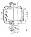
- Figure 1 the left hand portion is an axial sectional view of a centrifugal pulpwood grinder 10 which includes a cap-like top frame 12, a cylindrical outer stone mounting frame 14 having two outwardly extending flanges 15 and 16 at its opposite ends, and a bottom frame 18 which will be described in greater detail below.
- a centrifugal pulpwood grinder 10 which includes a cap-like top frame 12, a cylindrical outer stone mounting frame 14 having two outwardly extending flanges 15 and 16 at its opposite ends, and a bottom frame 18 which will be described in greater detail below.
- Securely mounted within the stone mounting frame are a plurality of stone segments 20 which provide a radially symmetrical, concave, cylindrical, inside grinding surface 22.
- the stone segments may be of hexagonal shape.
- a drive shaft 27 Mounted centrally of the grinding chamber 24 on conical bearings of which one is shown in Figure 1 at the numeral 26 is a drive shaft 27, to which a rotary hub 28 is affixed by means of a key 29.
- Extending substantially radially away from the hub 28 are two or three hollow arms 30 adapted to propel the pulpwood circumferentially along and around the grinding surface 22.
- each arm 30 rotates about the axis 31 in the direction of the arrow 32, and undergoes a gradual curvature so that its distal portion 34 slopes toward the rear compared to the direction of rotation.
- the distal portion 34 has a plurality of engagement teeth 36 along its forward surface, the teeth 36 being adapted to engage a piece of pulpwood 38 in order to stabilize the same as it rotates against the grinding surface 22, and in order to minimize bounce or rolling of the pulpwood 38.
- the hollow arm has, at its distal end, an adjustable finger bar 40, which may be a stainless steel casting, which is adapted to ride in close proximaty to the grinding surface 22 to ensure that the slurry of water and ground pulp in the vicinity of the pulpwood 38 will also be swept circumferentially around the grinding surface 22, and thus “flung" outwardly against the grinding surface 22 by reason of the centrifugal force.
- an adjustable finger bar 40 which may be a stainless steel casting, which is adapted to ride in close proximaty to the grinding surface 22 to ensure that the slurry of water and ground pulp in the vicinity of the pulpwood 38 will also be swept circumferentially around the grinding surface 22, and thus “flung” outwardly against the grinding surface 22 by reason of the centrifugal force.
- the bottom frame 18 includes a shredder shown generally by the numeral 43, the shredder 43 including a stator 45 and rotor 47, the rotor being an integral part of a disk-like rotating bottom wall 48 which is integral with the hub 28.
- the rotor 47 is provided with a plurality of slots, as is also the stator 45, and the openings 46 of the two sets of slots pass across each other at high speeds, thus shredding the ground pulp material through a type of scissors or shearing action.
- the purpose of the shredding is to break up slivers which would otherwise tend to propagate a downstream jamming condition.
- the bottom frame 18 includes a wall 50 defining a volute constituted an evacuation zone for thu pulp slurry.
- An opening (not shown) is provided for removing the pulp slurry from the evacuation zone.
- a bearing seal is shown generally by the numeral 53, and includes a stationary ring 54 of L-shape, which is urged upwardly against the bottom of an annular downward projection 56 integral with the hub 28 by a spring 57.
- annular plate 59 At the top of the hollow arms 30 is an annular plate 59 which, along with the portion 48, defines a containment zone for the aqueous pulp slurry which results from the grinding process.
- each arm 30, while connected to the hub 28, also has a free inner edge 61 which terminates at the inner circumference 62 of the annular plate 59. Thus, there is defined a central opening 64 into which the pieces of pulpwood 38a can fall.
- the hub 28 may not require the length shown in Figure 1, and may terminate at a location closer to the key 29. It is also contemplated that the entire grinding chamber 24 could be additionally pressurized above atmospheric by the use of single or double seals (not shown), so that the pressure undergone by the aqueous slurry being centrifuged around and against the grinding surface 22 would be greater than atmospheric by reason of both the centrifugal effect and the additional pressurization.
- Figures 1 and 2 While the embodiment shown in Figures 1 and 2 is adapted for vertical orientation, i.e. with the axis of rotation extending vertically, the arrangement shown schematically in Figure 3 is shown in a horizontal orientation.
- the purpose of Figure 3 is essentially to show how water can be ducted into a location adjacent the grinding surface 22a, and that the centrifuging effect of the rotation of the arms 30 will also produce an increase in the pressure of the water available at nozzles 67.
- a water supply arrangement similar to that of Figure 3 is provided in the embodiment of Figures 1 and 2, although not shown in those Figures.
- an electric motor 71 rotates the input shaft 72 of a reduction gear box 74, of which the output shaft 75 rotates the hollow arms that are represented in Figure 3 merely by the water piping 77.
- a cylindrical, internal grinding surface 90 is defined by cylindrical sections of suitable stone 92, which are retained in place by a stone retaining frame 94.
- a housing 96 Connected in a sealed manner with the stone retaining frame 94 is a housing 96, which is sealed at the left in Figure 4 with respect to a bearing housing 99, and is sealed at the right in Figure 4 wtih respect to a bearing housing 101.
- the bearing housing 101 at the right in Figure 4 is connected to a pilot shaft bearing housing 104 containing a series of roller bearing 105 which centrally support a pilot shaft 107 for rotation about a central axis 109.
- the bearing housing 99 is connected to a drive shaft bearing housing 112 of conventional construction which supports two roller bearings 113 and 115, which centrally support for rotation a low speed drive shaft 117 which, together with the pilot shaft 107, securely supports a rotor 120 for rotation about the axis defined by the line 109.
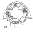
- the rotor 120 consists essentially of two end plates 122 and 123, which support between them two axially extending sickle-shaped members 125 and 126 (see Figure 5). More specifically, each of the sickle-shaped members 125 and 126 includes an outwardly extending portion 129, and a substantially part-cylindrical portion 131 which is eccentrically located with respect to the axis 109 of the rotor per se. More specifically, looking at Figure 5, the center of curvature of the leftward part-cylindrical portion 131 is located at 134, while the center of curvature of the rightward part-cylindrical portion 131 is located at 136.
- the logs As the logs come into contact with the members 125 and 126, since the portions 131 thereof become progressively further and further from the axis 109 in the counter-clockwise direction as pictured in Figure 5, the logs likewise will tend to roll or move in the counter clockwise direction with respect to members 125 and 126, thus approaching the end regions thereof, where there is a spacing between the members 125 and 126, the spacing being such as to allow the logs to move outward under centrifugal force and contact the inside cylindrical surface 90 of the grinding stone segments.
- the rotor design shown in Figure 5 provides a "fluid centre" which avoids a situation developing wherein one pocket is fully loaded while the other one, which may be empty, cannot accept logs because its entrance is blocked.
- a guide plate 143 which terminates close to the internal grinding surface 90.
- a finger bar 145 which serves the purpose of retaining the aqueous slurry constituted by the groundwood stock and the water added thereto, rotating about and against the internal grinding surface 90.
- the finger bars 145 are shaped to assist in the evacuation of the pulp to the sides of the stone.
- a suitable configuration for the finger bar at 145 is that described in CA-A-947,555, to Koehring--Waterous Ltd.
- the outer plates 122 and 123 of the rotor 120 are shaped as illustrated in Figure 5, the shape being essentially circular but having two outwardly extending antipodal ears 147.
- the ears 147 are intended to restrict the egress of unwanted slivers. This causes the slivers to remain in the grinding zone and ensures that they are ground out.
- the nominal outer periphery 150 of the plates 122 and 123 has a smaller diameter than the internal grinding surface 90, thus leaving a gap 152 therebetween, through which pulpwood stock can escape from the internal grinding surface 90.
- the ears 147 extend outwardly beyond the radius of the internal grinding surface 90, and thus overlap the grinding stones segments.
- each grinding cavity being defined laterally by two ears 147, outwardly by the grinding surface 90, forwardly by the plate 143 of one of the members 125 and 126, and rearwardly by the portion 129 and finger bar 145 of the other of the members 125 and 126.
- the logs are flung or urged centrifugally into these grinding cavities, and are there ground into stock.
- bearing housings 99 and 101 define the outer limit for two annular stock/oil mechanical seals 156, which bear internally against the low speed drive shaft 117 and the pilot shaft 107 respectively.
- the housing 96 defines the upper portion of a chamber within which the rotor 120 rotates, the chamber retaining the pulpwood stock and directing it downwardly.
- the lower part of the chamber may, as illustrated in Figures 4 and 5, be located below the level of the mill floor 158 in a stock sump 160 provided therein.
- a stock exit passage way 162 At the bottom of the stock sump 160 is a stock exit passage way 162, which leads to a further processing step for the stock (this being of no concern to the present invention).
- Figure 6 shows an outside end view of the plate 123, being that on the left in Figure 4.
- Figure 6 shows that the leftward plate 123 includes in its periphery a recess 171, but that otherwise the plate 123 has the same shape as the plate 122 shown in Figure 5.
- Connected between the two plates 122 and 123 is an inverted V-shaped finger bar holder 173 to which is securely bolted or clamped a secondary finger bar 175, also of inverteu V-shaped.
- Figure 6 shows three fastening assemblies 178, which may be in the form of clamps or bolts.
- Figure 7 shows a direct elevational view of the rotor 120, seen from a direction which shows the secondary finger bar 175 and its holder 173 in true shape.
- the secondary finger bar 175 consists of two plate elements, each with a curving outside edge 181, having the same curvature as the internal grinding surface 90.
- the secondary finger bar 175 is considered an advantage in that it avoids too great a build-up of groundwood pulp stock on the internal grinding surface 90. Such a build-up could impair the grinding operation.
- the shower supply water is seen to enter from the left along a feed pipe 184, through a rotary seal 186 and into a central passageway 189 located axially of the low speed drive shaft 117.
- a plurality (in this case 4) of radial passageways 191 extend outwardly from and communicate with the passageway 189, the passageways 191 being defined by appropriate pipes or other conduits.
- the latter communicate with respective shower pipes 193 which extend axially with respect to the rotor 120, and which are braced between the plates 122 and 123.
- each of the removable shower pipes 193 is capped at the rightward end with a pipe cap 195, and has a plurality of nozzle openings 196 adjacent the internal grinding surface 90.
- rotation of the rotor 120 increases the pressure in the removable shower pipes 193, with respect to the pressure in the passageway 189, permitting the supply water entering along the pipe 184 to be less than the intended pressure in the removable shower pipe 193.
- the grinder structure herein disclosed has several advantages, and these are summarized below.
- the grinding assembly herein disclosed can be used to create pressurized effects but without the need for pressure lock mechanisms.
- the grinder of the present invention rotates more slowly than a refiner.
- the grinder of the present invention may rotate in the area of 500 rpm, as compared to 1800 rpm for a disk refiner. Thus less power is absorbed than in a refiner (in this specific area), and the chip reaches the working surface of the grinder in better condition due to the lower speed.
- the grinding pressure can be controlled accurately by providing means for varying the rotor speed, since this will govern the centrifugal force generated.
- a further option would be to utilize a grinding stone surface which is other than cylindrical, for example a conical surface having a profile as shown by the broken line 197 in Figure 1. This could be used to aid both stock evacuation and rotor-to-stone clearance adjustment. Such an option may well apply to the chip grinding process in particular, where the clearance between the stone and the rotor is more critical, and the variation in peripheral speed due to the varying diameter is of lesser importance.
- the stone design for the present construction consists of vitrified sections set into the steel rim or frame 94. This will permit the provision of a stone having less weight and complexity than traditional structures. A further option is the eventual design of the stone housing so that it forms a jacket for cooling purposes.
Landscapes
- Engineering & Computer Science (AREA)
- Life Sciences & Earth Sciences (AREA)
- Wood Science & Technology (AREA)
- Mechanical Engineering (AREA)
- Grinding Of Cylindrical And Plane Surfaces (AREA)
- Paper (AREA)
- Crushing And Grinding (AREA)
Claims (17)
Applications Claiming Priority (4)
| Application Number | Priority Date | Filing Date | Title |
|---|---|---|---|
| GB8136864 | 1981-12-07 | ||
| GB8136864 | 1981-12-07 | ||
| US383713 | 1982-06-01 | ||
| US06/383,713 US4474335A (en) | 1981-12-07 | 1982-06-01 | Apparatus for centrifugal pulpwood and wood chip grinding |
Publications (3)
| Publication Number | Publication Date |
|---|---|
| EP0081380A2 EP0081380A2 (de) | 1983-06-15 |
| EP0081380A3 EP0081380A3 (en) | 1984-10-03 |
| EP0081380B1 true EP0081380B1 (de) | 1987-03-04 |
Family
ID=26281479
Family Applications (1)
| Application Number | Title | Priority Date | Filing Date |
|---|---|---|---|
| EP82306519A Expired EP0081380B1 (de) | 1981-12-07 | 1982-12-07 | Verfahren und Vorrichtung zur Mahlen von Pulpholz und Holzspanen durch Fliehkraft |
Country Status (4)
| Country | Link |
|---|---|
| EP (1) | EP0081380B1 (de) |
| DE (1) | DE3275568D1 (de) |
| FI (1) | FI69138C (de) |
| NO (1) | NO157829C (de) |
Family Cites Families (1)
| Publication number | Priority date | Publication date | Assignee | Title |
|---|---|---|---|---|
| AT118812B (de) * | 1928-10-29 | 1930-08-25 | Andreas Biffar | Verfahren und Vorrichtung zum Schleifen von Holz. |
-
1982
- 1982-12-02 NO NO824045A patent/NO157829C/no unknown
- 1982-12-02 FI FI824157A patent/FI69138C/fi not_active IP Right Cessation
- 1982-12-07 DE DE8282306519T patent/DE3275568D1/de not_active Expired
- 1982-12-07 EP EP82306519A patent/EP0081380B1/de not_active Expired
Also Published As
| Publication number | Publication date |
|---|---|
| DE3275568D1 (en) | 1987-04-09 |
| EP0081380A2 (de) | 1983-06-15 |
| FI824157L (fi) | 1983-06-08 |
| FI69138B (fi) | 1985-08-30 |
| NO157829B (no) | 1988-02-15 |
| FI824157A0 (fi) | 1982-12-02 |
| FI69138C (fi) | 1985-12-10 |
| NO824045L (no) | 1983-06-08 |
| NO157829C (no) | 1988-06-08 |
| EP0081380A3 (en) | 1984-10-03 |
Similar Documents
| Publication | Publication Date | Title |
|---|---|---|
| US5373995A (en) | Vented refiner and venting process | |
| US3387796A (en) | Defibrating device | |
| EP1157160B1 (de) | Scheibenmühle mit tangentialem austritt | |
| US4401280A (en) | Disc-type pulp refining apparatus | |
| JPS54138601A (en) | Method and apparatus for purifying pulp material | |
| US4283016A (en) | Method and apparatus for controlling the effect of the centrifugal force on the stock in pulp defibrating apparatus | |
| US5335865A (en) | Two-stage variable intensity refiner | |
| US2912174A (en) | Method and apparatus for the treatment of paper stocks | |
| US4878997A (en) | Method and apparatus for manufacturing fibre pulp | |
| GB2083375A (en) | Disc mills | |
| US2991949A (en) | Rock crushing machine | |
| US4474335A (en) | Apparatus for centrifugal pulpwood and wood chip grinding | |
| CA2278373C (en) | Refiner disc having steam exhaust channel | |
| US4725336A (en) | Refiner apparatus with integral steam separator | |
| JPH01250485A (ja) | 繊維質材料を粉砕する粉砕装置 | |
| EP0081380B1 (de) | Verfahren und Vorrichtung zur Mahlen von Pulpholz und Holzspanen durch Fliehkraft | |
| EP0168398A1 (de) | Verfahren und vorrichtung zur herstellung einer faserpulpe | |
| US3467323A (en) | Grinding apparatus | |
| AU8155087A (en) | Refiner | |
| US3241775A (en) | Apparatus and method for reducing the size of particles | |
| KR19990008275A (ko) | 원추형 리본피더가 있는 디스크 정제기 | |
| CA1317499C (en) | Apparatus for crushing or grinding of fibrous material, in particular drum refiner | |
| SU1559026A1 (ru) | Установка дл измельчени волокнистого материала | |
| US4395047A (en) | Shaft seal with seal impeller for materials processing machinery | |
| US3960333A (en) | Fluidic mill |
Legal Events
| Date | Code | Title | Description |
|---|---|---|---|
| PUAI | Public reference made under article 153(3) epc to a published international application that has entered the european phase |
Free format text: ORIGINAL CODE: 0009012 |
|
| 17P | Request for examination filed |
Effective date: 19821221 |
|
| AK | Designated contracting states |
Designated state(s): DE FR GB SE |
|
| PUAL | Search report despatched |
Free format text: ORIGINAL CODE: 0009013 |
|
| AK | Designated contracting states |
Designated state(s): DE FR GB SE |
|
| GRAA | (expected) grant |
Free format text: ORIGINAL CODE: 0009210 |
|
| AK | Designated contracting states |
Kind code of ref document: B1 Designated state(s): DE FR GB SE |
|
| REF | Corresponds to: |
Ref document number: 3275568 Country of ref document: DE Date of ref document: 19870409 |
|
| ET | Fr: translation filed | ||
| PLBE | No opposition filed within time limit |
Free format text: ORIGINAL CODE: 0009261 |
|
| STAA | Information on the status of an ep patent application or granted ep patent |
Free format text: STATUS: NO OPPOSITION FILED WITHIN TIME LIMIT |
|
| 26N | No opposition filed | ||
| PGFP | Annual fee paid to national office [announced via postgrant information from national office to epo] |
Ref country code: SE Payment date: 19911106 Year of fee payment: 10 |
|
| PGFP | Annual fee paid to national office [announced via postgrant information from national office to epo] |
Ref country code: DE Payment date: 19911129 Year of fee payment: 10 |
|
| PGFP | Annual fee paid to national office [announced via postgrant information from national office to epo] |
Ref country code: GB Payment date: 19911205 Year of fee payment: 10 |
|
| PGFP | Annual fee paid to national office [announced via postgrant information from national office to epo] |
Ref country code: FR Payment date: 19911230 Year of fee payment: 10 |
|
| PG25 | Lapsed in a contracting state [announced via postgrant information from national office to epo] |
Ref country code: GB Effective date: 19921207 |
|
| PG25 | Lapsed in a contracting state [announced via postgrant information from national office to epo] |
Ref country code: SE Effective date: 19921208 |
|
| GBPC | Gb: european patent ceased through non-payment of renewal fee |
Effective date: 19921207 |
|
| PG25 | Lapsed in a contracting state [announced via postgrant information from national office to epo] |
Ref country code: FR Effective date: 19930831 |
|
| PG25 | Lapsed in a contracting state [announced via postgrant information from national office to epo] |
Ref country code: DE Effective date: 19930901 |
|
| REG | Reference to a national code |
Ref country code: FR Ref legal event code: ST |
|
| EUG | Se: european patent has lapsed |
Ref document number: 82306519.8 Effective date: 19930709 |