EP0081081A1 - Process and apparatus for CO2 laser excitation - Google Patents
Process and apparatus for CO2 laser excitation Download PDFInfo
- Publication number
- EP0081081A1 EP0081081A1 EP82110042A EP82110042A EP0081081A1 EP 0081081 A1 EP0081081 A1 EP 0081081A1 EP 82110042 A EP82110042 A EP 82110042A EP 82110042 A EP82110042 A EP 82110042A EP 0081081 A1 EP0081081 A1 EP 0081081A1
- Authority
- EP
- European Patent Office
- Prior art keywords
- laser
- gas
- discharge
- chamber
- storage
- Prior art date
- Legal status (The legal status is an assumption and is not a legal conclusion. Google has not performed a legal analysis and makes no representation as to the accuracy of the status listed.)
- Granted
Links
Images


Classifications
-
- H—ELECTRICITY
- H01—ELECTRIC ELEMENTS
- H01S—DEVICES USING THE PROCESS OF LIGHT AMPLIFICATION BY STIMULATED EMISSION OF RADIATION [LASER] TO AMPLIFY OR GENERATE LIGHT; DEVICES USING STIMULATED EMISSION OF ELECTROMAGNETIC RADIATION IN WAVE RANGES OTHER THAN OPTICAL
- H01S3/00—Lasers, i.e. devices using stimulated emission of electromagnetic radiation in the infrared, visible or ultraviolet wave range
- H01S3/02—Constructional details
- H01S3/03—Constructional details of gas laser discharge tubes
- H01S3/036—Means for obtaining or maintaining the desired gas pressure within the tube, e.g. by gettering, replenishing; Means for circulating the gas, e.g. for equalising the pressure within the tube
-
- H—ELECTRICITY
- H01—ELECTRIC ELEMENTS
- H01S—DEVICES USING THE PROCESS OF LIGHT AMPLIFICATION BY STIMULATED EMISSION OF RADIATION [LASER] TO AMPLIFY OR GENERATE LIGHT; DEVICES USING STIMULATED EMISSION OF ELECTROMAGNETIC RADIATION IN WAVE RANGES OTHER THAN OPTICAL
- H01S3/00—Lasers, i.e. devices using stimulated emission of electromagnetic radiation in the infrared, visible or ultraviolet wave range
- H01S3/09—Processes or apparatus for excitation, e.g. pumping
- H01S3/097—Processes or apparatus for excitation, e.g. pumping by gas discharge of a gas laser
- H01S3/0971—Processes or apparatus for excitation, e.g. pumping by gas discharge of a gas laser transversely excited
- H01S3/09713—Processes or apparatus for excitation, e.g. pumping by gas discharge of a gas laser transversely excited with auxiliary ionisation, e.g. double discharge excitation
Definitions
- the invention relates to a method for operating a C0 2 gas laser within a closed housing, which with electronics that cause electrical discharge, a voltage supply, a discharge or resonator space and, if necessary, with additional spaces connected to the discharge or resonator space is provided and on a device for performing this method.
- Such a gas laser is the subject of patent application P 31 23 049.0, for example. Similar lasers are also described in patent application P 30 44 023.4-33 or European application 81 101440.6.
- this typical gas discharge of electrically pumped C0 z lasers various chemical and physical processes, some of which are interdependent, occur, which can lead to certain changes in the laser function. This can be caused, for example, by the adsorption of ions, atoms and molecules on inner surfaces, the emission from surfaces and electrodes, by surface reactions, interactions with ions, atoms, molecules and UV quanta in the electrical discharge or by diffusion processes through walls will. Since very complex reactions therefore take place in the case of gas discharges from lasers, such as the type described in more detail above, the production of stable equilibrium states is comparatively difficult. So far, the reactions have been more or less uncontrolled.
- the catalyst provided - e.g. is heated with part of the charging energy
- a further development of the invention provides that highly porous solids or substances with large specific surfaces with or without grooves, notches, nets, tubes or holes are used as substances with surface-enlarging structures, the function of which can be improved by pressure and / or temperature changes.
- Cu, Ni or Pt surfaces have the advantage of allowing higher temperatures for gas discharge.
- a combination of a catalyst and an absorber and at least partially made of metal - for example platinum or Nickel - and ceramic - eg TiO 2 / MnO 2 -CuO - existing element is used and, if necessary, the element at least briefly at elevated temperature and - preferably - is operated near the anode of the voltage supply.
- laser gas or components - gaseous and / or chemically bound and / or physically bound gases e.g., gas or components - in the discharge or resonator chamber and / or the chamber connected to it.
- gas or components - in the discharge or resonator chamber and / or the chamber connected to it e.g., Carbon dioxide, hydrogen, water, helium - stored and - e.g. by diffusion and / or pressure and / or temperature - are continuously or intermittently supplied to the discharge or resonator chamber.
- dissociation products and subsequent compounds such as C0, H 2 0, 0 2 , 0 3 or nitrogen oxides etc. are produced.
- these can be continuously or intermittently discharged and / or chemically bound and / or physically bound by catalysts / absorbers and / or filters and / or adsorbers and / or membranes, with other / gas components, for example carbon dioxide, being fed in as required will.
- the heating or the catalyst itself can be designed as a high-resistance resistor running parallel to the discharge path. In this case, catalysis is only initiated if a discharge actually leads to dissociation.
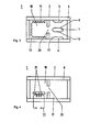
- FIG. 1 shows the schematic diagram of an elongated, transversely excited laser amplifier 1, which is designed, for example, as a CW (continuous wave), RF (radio frequency) or pulse-operated laser with regard to its type of control can be.
- Its housing 2 consists of a symmetrical hollow body made of metal, for example a non-magnetic metal such as aluminum, copper, tungsten, an alloy of these metals or a ferromagnetic metal.
- the hollow body has essentially the shape of a trough, in which an electrode 5 or 6 is fastened on the inside on the bottom side and on the cover 8.
- the width of the electrodes and their mutual spacing can be millimeters (in the case of a waveguide design) or centimeters and their length can be up to a few decimeters.
- the widths of both electrodes can be the same or different; in the latter case, the widths of the electrodes 6 and 5 can be dimensioned, for example, in a ratio of 4: 5 and work with a voltage of up to 30 kV. This results in field strengths of 10 to 25 kV / cm and energy densities of 0.1 to 0.5, for example 0.25 joules / cm 3 , of laser gas.
- Electrode 5 and voltage supply 11 with the voltage supply - for example, a high voltage supply - to the electrodes 5 and 6, so that an electrical discharge can take place in the gas between them, whereby the C0 2 gas molecules are excited.
- the switching pulse required for this has a half width of typically ⁇ 100 nsec and a rising edge of typical. ⁇ 20 nsec.
- the resonator arrangement 15 and 16 fastened to the end faces 3 and 4 in the space between the electrodes can then couple out optical energy from the housing 2.
- Electrode 5 and voltage supply 11 are electrically insulated from the rest of the housing by means of insulator 12.
- a substance 13 with a surface-enlarging structure which acts as a store or support for stores and / or a support for catalysts for solid liquid or gaseous laser gas components and / or Serves as catalysts.
- the electrodes 5 ', 6', 7 ' are fastened in channels 18 1 cast in the housing 2 or subsequently drilled and excite the laser in the longitudinal direction.
- FIG. 3 essentially shows a cross section of the laser amplifier 1 according to FIG. 1, in which a central electrode 7, for example attached to the cover 8, is also provided in the longitudinal axis of the housing 2, the discharge surfaces 9, 10 of the discharge surfaces of the electrodes 5 and 6 are turned. This creates a once folded beam path. In other exemplary embodiments that are not shown in the drawing, multiple folding and a correspondingly shorter design are also conceivable.
- Parallel to the resonator or discharge space 17 is the molded or subsequently attached to the housing 2 chamber 18, which has on its inner walls the fabric layer 13 with grooves 19 extending parallel to the longitudinal axis and enlarging the entire inner surface.
- Ceramic, quartz, (quartz) glass, metal, sintered material, clay (earth), porcelain, Al-oxide or Al-silicate with a sufficiently high specific surface come into consideration as materials of this storage or carrier, while water (material ), Carbon monoxide, formaldehyde, alcohol, carbonyl, copper, nickel, platinum, titanium, palladium or a mixture of Mn0 2 / Cu0 is possible.
- catalysts or laser components or other memories made of precious metals - for example titanium, metal oxides - for example Mn0 2 and / or Cu0 -, carbon, hydroxides - for example palladium hydroxide -, carbonates - for example silver carbonate - or combinations of noble metals and metal oxides and / or at least part of the activated surfaces with CO and another part with 0 2 can chemical bonds, burn-in, vapor deposition, flame blasting or plasma spraying can be attached to the surfaces of the storage or carrier, for example by diffusion.
- the two chambers (resonator or discharge chamber 17 and chamber 18) are connected to one another via the opening 20.
- different absorbers 21 - combined if necessary with a heating and / or cooling device 22 - can be used in the chamber 18.
- this type of heating or cooling device regardless of the discharge energy, changes in volume and / or temperature of the total pressure within the system or individual partial pressures such as or cooling monoxide, e.g. of hydrogen.
- cooling monoxide e.g. of hydrogen.
- carbon monoxide water vapor, methane, ethane, higher hydrocarbons, carbonates, carbonyls, formaldehyde, either individually or in combination with one or more of these substances - through the opening 20 - the pressure, volume and temperature conditions within the resonator can be - Influence or discharge space 17.
- an element combined from catalyst and absorber 21 is used in a longitudinally excited laser amplifier 1, which is arranged near the anode 7 'and its voltage supply 11.
- carbon can be converted into carbon dioxide or nitrogen oxides into nitrogen.
- the catalyst can be a metallic absorber, for example, and the absorber can be a water absorber, for example made of ceramic Ti0 2 / MnO 2 -CuO or Pt on aluminum oxide.
- Pressure, volume and temperature conditions and the dissipation of dissociation products can, however, also be stored in the discharge or resonator chamber 17 according to FIG. 6 or else in a chamber connected to this chamber, for example according to FIGS. 3 and 4 2 - (Laser) gas or components - gaseous and / or chemically bound and / or '' affect physically bound gases, e.g. carbon dioxide, water (material), helium.
- These substances can be continuously or intermittently supplied to the discharge or resonator chamber from the reservoir 19 via the nozzle 23, for example under pressure and / or optionally by influencing the temperature and / or diffusion, or the dissociation products can be removed accordingly.
- the absorbers 21 - also adsorbers, filters or membranes - for these dissociation products are of a very specific nature.
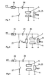
- FIGS. 7 to 9 show a possibility which, regardless of or in addition to the gas chemistry treated in the previous exemplary embodiments, causes a back reaction of CO and 0 2 in C0 2 .
- the coupling resistor R h ochohmige Ko pp el in form of a wire 24 is shown in Fig. 7 is provided, which runs parallel to the plane formed by the electrodes 5 and 6, the discharge path.
- the coupling resistor 24 itself is designed as a catalyst.
- this catalytic converter is provided, for example, in the form of a resistor R Kat , which also runs parallel to the discharge path and has the reference number 25, while in FIG. 9, as it were in reverse to FIG.
- the catalyst is heated with a small part of the charging energy with each discharge or charge.
- the charging current limiting circuit breaker R L by numeral 26 may - in modification of the embodiments according to Figures 8 and.. Fig. 9 - also replace the catalyst 25.
- the reference number 27 denotes the pulse switch and 28 a storage capacitor.
- the circuits shown are only given as examples. In principle, all circuits typical for the operation of a laser (Blümlein K rice and the like) are conceivable without thereby departing from the scope of the invention.
- the dissociation and the subsequent reactions of the C0 2 molecule are selected:
- the laser according to the invention was developed which provides bodies in the laser chamber or bodies with surface-enlarging structures which themselves serve as storage or as a support for storage of the catalysts which enable the equilibrium state of the laser function.
- the mirrors 15 and 16 must be replaced by end windows which are transparent to the radiation.
- a pulse is shot through one of these windows into the existing medium immediately after the discharge between the electrodes, which usually has a nicer beam profile and a lower power.
- the total impulse then leaving the housing through the other window is amplified by approximately 3 to 10%.
Abstract
In CO2-Gaslasern, die elektrisch gepumpt werden, laüfen sehr verschiedene chemische und physikalische Vorgänge ab, die wenigstens teilweise zu unerwünschten Wechselwirkungen der Gase untereinander und/oder der Gase mit dem elektrischen und/oder optischen Feld und/oder der verwendeten Materialien in den Gasräumen führen. Durch Einbringen von mit oberflächenvergrößernden Strukturen versehenen Körpern (13) in den Entladungs- bzw. Resonatorraum (17) oder benachbarte Kammern, die selbst als Speicher oder als Träger von Speichern für geeignete Katalysatoren und Gaskomponenten dienen können und/oder durch eine elektrische Beheizung der Katalysatoren sowie durch gezielte Beeinflussung der Volumen- und/oder Druck- und/oder Temperaturverhältnisse läßt sich zumindest annähernd ein Gleichgewichtszustand erzielen, der zu gleichbleibend guter elektrischer Entladung und langer Lebensdauer bei hohem Laserwirkungsgrad führt.In CO2 gas lasers, which are pumped electrically, very different chemical and physical processes take place, which at least partially lead to undesired interactions of the gases with one another and / or the gases with the electrical and / or optical field and / or the materials used in the gas spaces to lead. By introducing bodies (13) provided with surface-enlarging structures into the discharge or resonator space (17) or adjacent chambers, which can themselves serve as stores or as supports for stores for suitable catalysts and gas components and / or by electrically heating the catalysts and by deliberately influencing the volume and / or pressure and / or temperature conditions, an equilibrium state can be achieved at least approximately, which leads to consistently good electrical discharge and a long service life with high laser efficiency.
Description
Die Erfindung bezieht sich auf ein Verfahren zum Betreiben eines C02-Gaslasers innerhalb eines geschlossenen Gehäuses, das mit einer die elektrische Entladung bewirkenden Elektronik, einer Spannungszufuhr, einem Entladungs- bzw. Resonatorraum und bedarfsweise mit zusätzlichen mit dem Entladungs- bzw. Resonatorraum verbundenen Räumen versehen ist sowie auf eine Vorrichtung zur Durchführung dieses Verfahrens.The invention relates to a method for operating a C0 2 gas laser within a closed housing, which with electronics that cause electrical discharge, a voltage supply, a discharge or resonator space and, if necessary, with additional spaces connected to the discharge or resonator space is provided and on a device for performing this method.
Ein solcher Gaslaser ist z.B. Gegenstand der Patentanmeldung P 31 23 049.0. Auch in der Patentanmeldung P 30 44 023.4-33 oder der Europaanmeldung 81 101440.6 sind ähnliche Laser beschrieben. Bei dieserart typischen Gasentladungen elektrisch gepumpter C0z-Laser treten verschiedene z.T. voneinander abhängige chemische und physikalische Vorgänge auf, die zu gewissen Veränderungen in der Laserfunktion führen können. Dies kann z.B. durch die Adsorption von Ionen, Atomen und Molekülen an inneren Oberflächen, die Abgasung aus Oberflächen und Elektroden, durch Oberflächenreaktionen, Wechselwirkungen mit Ionen, Atomen, Molekülen und UV-Quanten in der elektrischen Entladung oder aber aufgrund von Diffusionsvorgängen durch Wandungen hindurch hervorgerufen werden. Da somit bei Gasentladungen von Lasern, wie z.B. der oben näher bezeichneten Gattung , sehr komplexe Reaktionen stattfinden, ist die Herstellung stabiler Gleichgewichtszustände vergleichsweise schwierig. Die Reaktionen verliefen daher bisher mehr oder weniger unkontrolliert.Such a gas laser is the subject of patent application P 31 23 049.0, for example. Similar lasers are also described in patent application P 30 44 023.4-33 or European application 81 101440.6. In this typical gas discharge of electrically pumped C0 z lasers, various chemical and physical processes, some of which are interdependent, occur, which can lead to certain changes in the laser function. This can be caused, for example, by the adsorption of ions, atoms and molecules on inner surfaces, the emission from surfaces and electrodes, by surface reactions, interactions with ions, atoms, molecules and UV quanta in the electrical discharge or by diffusion processes through walls will. Since very complex reactions therefore take place in the case of gas discharges from lasers, such as the type described in more detail above, the production of stable equilibrium states is comparatively difficult. So far, the reactions have been more or less uncontrolled.
Aufgabe der Erfindung ist es, eine möglichst unveränderte und stabile Laserfunktion, d.h. einen Gleichgewichtszustand möglichst aller Wechselwirkungen der Gase mit dem elektrischen und optischen Feld, der Materialien in den Gasräumen und -kammern sowie der Gase untereinander zu erzielen. Diese Aufgabe wird erfindungsgemäß dadurch gelöst, daß entweder
- a) kammer-, wannenförmig oder nach Art eines Wellenleiterlasers kanalförmig ausgebildete Räume verwendet werden,
- b) in den Laser-Räumen Stoffe mit oberflächenvergrößernden Strukturen als Speicher oder Träger von Speichern und/oder Träger von Katalysatoren angeordnet werden,
- c) Speicher und/oder Träger für weitere Lasergaskomponenten fester, flüssiger oder gasförmiger Konsistenz und/oder Katalysatoren verwendet werden und
- d) in den Laser-Räumen der Gesamtdruck oder die Partialdrücke der einzelnen Lasergaskomponenten mit Hilfe von Druckgefäßen definierter Leckrate und/oder von Druck- und/oder Volumenveränderungen und/oder mit Hilfe von Temperaturveränderungen eingestellt werden
- a) chambers, trough-shaped or channel-shaped spaces in the manner of a waveguide laser are used,
- b) substances with surface-enlarging structures are arranged in the laser rooms as stores or carriers of stores and / or carriers of catalysts,
- c) storage and / or carrier for further laser gas components of solid, liquid or gaseous consistency and / or catalysts are used and
- d) the total pressure or the partial pressures of the individual laser gas components are set in the laser rooms with the aid of pressure vessels with a defined leak rate and / or with pressure and / or volume changes and / or with the aid of temperature changes
oder aber, daß bei jeder Ent- bzw. Aufladung des elektrischen .Energiespeichers der vorgesehene Katalysator - z.d. mit einem Teil der Ladeenergie beheizt wirdor that each time the electric energy storage is discharged or charged, the catalyst provided - e.g. is heated with part of the charging energy
oder daß die Beheizung in Kombination mit einem oder mehreren der Merkmale nach a) bis d) erfolgt.or that the heating takes place in combination with one or more of the features according to a) to d).
Auf diese Weise, kann eine saubere Zustandsform des Lasers und vor allem seines Inneren erzielt werden, so daß das elektrische Entladen selbst bei extremen - insbesondere tiefen - Temperaturen, bei besonderen Anforderungen bezüglich Leistung, Energie, Wirkungsgrad, Pulsform und Wellenlänge, bei Gasmischungen mit ungünstiger Chemie, hohen Drücken und Pulsfolgefrequenzen sowie bei Betrieb ohne zusätzliche Vorionisation bzw. ohne zusätzliche Maßnahmen, wie z.B. spezifische Gasbeimischungen, erleichtert und eine lange Lebendauer erzielt wird.In this way, a clean state of the laser and especially its interior can be achieved, so that the electrical discharge even at extreme - especially low - temperatures, with special requirements with regard to power, energy, efficiency, pulse shape and wavelength, with gas Mixtures with unfavorable chemicals, high pressures and pulse repetition frequencies as well as during operation without additional pre-ionization or without additional measures, such as specific gas admixtures, are facilitated and a long service life is achieved.
Eine Weiterbildung der Erfindung sieht vor, daß als Stoffe mit oberflächenvergrößernden Strukturen hochporöse Festkörper oder Stoffe mit großen spezifischen Oberflächen mit oder ohne Rillen, Kerben, Netzen, Rohren oder Löchern verwendet werden, deren Funktion durch Druck- und/oder Temperaturänderungen verbessert werden kann.A further development of the invention provides that highly porous solids or substances with large specific surfaces with or without grooves, notches, nets, tubes or holes are used as substances with surface-enlarging structures, the function of which can be improved by pressure and / or temperature changes.
In vorstehendem Zusammenhang bietet sich als besonders vorteilhaft an, daß
- a) als Speicher oder Träger oder zumindest als deren zu aktivierende Flächen, Keramik, Quarz, (Quarz-) Glas, Metall, Sintermaterialien, Ton(erde), Porzellan, Al-Oxid oder Al-Silikat von hinreichend hoher spezifischer Oberfläche verwendet werden,
- b) die Speicher, Träger oder deren genutzte Flächen mit - z.B. eindiffundierten, chemisch gebundenen, eingebrannten oder durch Aufdampfen, Flammstrahlen oder Plasmaspritzen aufgebrachten-Katalysatoren oder Lasergaskomponenten oder mit weiteren Speichern versehen werden,
- c) als weitere Speicher bzw. Katalysatoren Edelmetalle - z.B. Palladium oder Platin -, Metalle - z.B. Titan -, Metalloxide - z.B. Mn02 und/oder Cu0 -, Kohle, Hydroxide - z.B. Palladium-Hydroxid -, Karbonate - z.B. Silberkarbonat - oder Kombinationen von Edelmetallen und Metalloxiden verwendet werden und/oder wenigstens ein Teil der aktivierten Oberflächen mit CO und ein anderer Teil mit 02 stabilisiert wird und
- d) als Katalysator (Wasser(stoff), Kohlenmonoxid, Formaldehyd, Alkohol, Karbonyl, Kupfer, Nickel, Platin, Titan, Palladium oder ein Gemisch von MnO2/CuO verwendet wird.
- a) are used as storage or carrier or at least as their surfaces to be activated, ceramics, quartz, (quartz) glass, metal, sintered materials, clay (earth), porcelain, Al-oxide or Al-silicate with a sufficiently high specific surface,
- b) the stores, supports or their used surfaces are provided with - for example diffused, chemically bonded, burned-in or applied by vapor deposition, flame blasting or plasma spraying - catalysts or laser gas components or with further stores,
- c) as further storage or catalysts noble metals - for example palladium or platinum -, metals - for example titanium -, metal oxides - for example Mn0 2 and / or Cu0 -, carbon, hydroxides - for example palladium hydroxide -, carbonates - for example silver carbonate - or combinations of precious metals and metal oxides are used and / or at least part of the activated surfaces is stabilized with CO and another part with 0 2 and
- d) is used as a catalyst (water (substance), carbon monoxide, formaldehyde, alcohol, carbonyl, copper, nickel, platinum, titanium, palladium or a mixture of MnO 2 / CuO.
Cu-, Ni- oder Pt-Oberflächen zeigen dabei den Vorteil, höhere Temperaturen bei der Gasentladung zu ermöglichen.Cu, Ni or Pt surfaces have the advantage of allowing higher temperatures for gas discharge.
Sofern man Rückreaktionen durchführen oder dieselben auch nur - da sie in der Regel träge verlaufen - beschleunigen möchte, ist es zweckmäßig, daß
- a) Wasserstoff durch Gasmischung und/oder Speicherung - z.B. in Palladium oder Titan auf etwa 0,2 bis 15 Volumenprozent und ein Wasserdampfdruck von etwa 0,1 bis 10 Torr eingestellt wird und/oder
- b) Kohlenmonoxid von etwa 1 bis 20 und/oder Wasserdampf von etwa 0,1 bis 10 und/oder Methan und/oder Äthan und/oder höhere Kohlenwasserstoffe zusammen bis etwa 10 Volumenprozent und/oder Katonate und/oder Karbonyle und/oder Formaldehyd. in polymerisierter - z.B. in Keramik eingelagerter - Form zugegeben werden.
- a) hydrogen is adjusted by gas mixing and / or storage - for example in palladium or titanium to about 0.2 to 15 percent by volume and a water vapor pressure of about 0.1 to 10 torr and / or
- b) carbon monoxide from about 1 to 20 and / or water vapor from about 0.1 to 10 and / or methane and / or ethane and / or higher hydrocarbons together up to about 10 volume percent and / or catonates and / or carbonyls and / or formaldehyde. in a polymerized form, for example in a ceramic form.
Weitere sinnvolle Maßnahmen, durch die vor allem die für eine Entladung schädliche Negativ-Ionen-Bildung sowie die 02-und Q3-Konzentrationen in vertretbaren Grenzen gehalten werden, sind Gegenstand der Ansprüche 5 und 6.Further sensible measures, by means of which the negative ion formation which is harmful to a discharge and the 0 2 and Q 3 concentrations are kept within reasonable limits, are the subject of
Wegen der Häufigkeit der CO2-Dissoziation ist es nach weiteren Merkmalen der Erfindung vorteilhaft, daß zum überführen von Kohlenstoff und Kohlenmonoxid in Kohlendioxid und/oder von Stickoxiden in Stickstoff ein aus einem Katalysator und einem Absorber kombiniertes und zumindest teilweis aus Metall - z.B. Platin oder Nickel - und Keramik - z.B. TiO2/MnO2-CuO - bestehendes Element verwendet wird und bedarfsweise das Element wenigstens kurzzeitig bei erhöhter Temperatur und - bevorzugt - nahe der Anode der Spannungszufuhr betrieben wird.Because of the frequency of CO 2 dissociation, it is advantageous according to further features of the invention that for converting carbon and carbon monoxide into carbon dioxide and / or nitrogen oxides into nitrogen, a combination of a catalyst and an absorber and at least partially made of metal - for example platinum or Nickel - and ceramic - eg TiO 2 / MnO 2 -CuO - existing element is used and, if necessary, the element at least briefly at elevated temperature and - preferably - is operated near the anode of the voltage supply.
Es kann aber auch in manchen Fällen sinnvoll sein, daß im Entladungs- bzw. Resonatorraum und/oder der mit ihm verbundenen Kammer Lasergas oder Komponenten - gasförmige und/oder chemisch gebundene und/oder physikalisch gebundene Gase, z.B. Kohlendioxid, Wasserstoff, Wasser, Helium - gespeichert und - z.B. durch Diffusion und/oder Druck und/oder Temperatur - fortlaufend oder stoßweise dem Entladungs- bzw. Resonatorraum zugeführt werden.In some cases, however, it can also make sense for laser gas or components - gaseous and / or chemically bound and / or physically bound gases, e.g., gas or components - in the discharge or resonator chamber and / or the chamber connected to it. Carbon dioxide, hydrogen, water, helium - stored and - e.g. by diffusion and / or pressure and / or temperature - are continuously or intermittently supplied to the discharge or resonator chamber.
Beim Laser- bzw. Verstärkerbetrieb fallen Dissoziationsprodukte und Folgeverbindungen wie C0, H20, 02, 03 oder Stickoxide etc. an. Nach einem weiteren Merkmal der Erfindung können diese durch Katalysatoren/Absorber und/oder Filter und/oder Adsorber und/oder Membranen fortlaufend oder stoßweise abgeführt und/oder chemisch gebunden und/oder physikalisch gebunden werden, wobei bedarfsandere weise / Gaskomponenten, z.B. Kohlendioxid, zugeführt werden.During laser or amplifier operation, dissociation products and subsequent compounds such as C0, H 2 0, 0 2 , 0 3 or nitrogen oxides etc. are produced. According to a further feature of the invention, these can be continuously or intermittently discharged and / or chemically bound and / or physically bound by catalysts / absorbers and / or filters and / or adsorbers and / or membranes, with other / gas components, for example carbon dioxide, being fed in as required will.
Weitere Merkmale, die eine Vorrichtung zur Durchführung des erfindungsgemäßen Verfahrens behandeln, sind Gegenstand der Ansprüche 10 und 11.Further features that deal with a device for carrying out the method according to the invention are the subject of
Von einiger Bedeutung ist sodann noch, daß die Beheizung oder der Katalysator selbst als hochohmiger, parallel zur Entladestrecke verlaufender Widerstand ausgebildet sein kann. In diesem Fall wird die Katalyse nur dann eingeleitet, wenn es durch eine Entladung tatsächlich zu einer Dissoziation kommt.It is also of some importance that the heating or the catalyst itself can be designed as a high-resistance resistor running parallel to the discharge path. In this case, catalysis is only initiated if a discharge actually leads to dissociation.
Im folgenden werden an Hand einer Zeichnung Ausführungsbeispiele der Erfindung näher erläutert, wobei die in den einzelnen Figuren einander entsprechenden Teile dieselben Bezugszeichen aufweisen. Es zeigt
- Fig. 1 den Längsschnitt durch einen transversal angeregten Laser-Verstärker mit Gasspeicher bzw. Katalysator,
- Fig. 2 einen Laser-Verstärker gemäß Fig. 1, jedoch mit longitudinal angeregtem Laser, der bei entsprechender Dimensionierung auch als Wellenleiterlaser aufgebaut sein kann,
- Fig. 3 einen Querschnitt durch die Bauform gemäß Fig. 1 mit einer zusätzlichen, eine Innenauskleidung aufweisenden Kammer,
- Fig. 4 eine Ansicht entsprechend Fig. 3 mit einer Kombination von Katalysator/Absorber und Heiz- bzw. Kühleinrichtung in der zusätzlichen Kammer,
- Fig. 5 eine Ansicht entsprechend Fig. 2 mit einem heiz- und kühlbaren Absorber bzw. Katalysator,
- Fig. 6 den Laser-Verstärker entsprechend Fig. 5 mit für die einzelnen Dissoziationsprodukte spezifischen Absorbern, Adsorbern, Filtern oder Membranen und
- Fig. 7 Schaltkreise für die elektrische Beheizung,
- bis 9 Ausbildung und Anordnung eines Katalysators.
- 1 shows the longitudinal section through a transversely excited laser amplifier with gas storage or catalyst,
- FIG. 2 shows a laser amplifier according to FIG. 1, but with a longitudinally excited laser, which can also be constructed as a waveguide laser with the appropriate dimensions,
- 3 shows a cross section through the design according to FIG. 1 with an additional chamber having an inner lining,
- 4 is a view corresponding to FIG. 3 with a combination of catalyst / absorber and heating or cooling device in the additional chamber,
- 5 is a view corresponding to FIG. 2 with a heatable and coolable absorber or catalyst,
- 6 shows the laser amplifier corresponding to FIG. 5 with specific absorbers, adsorbers, filters or membranes for the individual dissociation products and
- 7 circuits for electrical heating,
- to 9 training and arrangement of a catalyst.
Fig. 1 zeigt die Prinzipskizze eines gestreckten, transversal angeregten Laser-Verstärkers 1, der hinsichtlich seiner Ansteuerungsart z.B. als CW- (continuous wave), RF-(radio frequency) oder als pulsbetriebener Laser ausgebildet sein kann. Sein Gehäuse 2 besteht aus einem symmetrischen Hohlkörper aus Metall, z.B. einem nichtmagnetischen Metall wie Aluminium, Kupfer, Wolfram, einer Legierung dieser Metalle oder einem ferromagnetischen Metall. Der Hohlkörper besitzt im wesentlichen Wannenform, bei dem an der Bodenseite und an dem Deckel 8 innenseitig je eine Elektrode 5 bzw. 6 befestigt ist.1 shows the schematic diagram of an elongated, transversely
Die Breite der Elektroden und ihr gegenseitiger Abstand können Millimeter (bei Wellenleiteroauform) oder Zentimeter und ihre Länge kann bis zu einige Dezimeter betragen. Die Breiten beider Elektroden können gleich oder unterschiedlich sein; in letzterem Fall können die Breiten der Elektroden 6 und 5 z.B. in einem Verhältnis von 4 : 5 bemessen sein und mit einer Spannung von bis zu 30 kV arbeiten. Hieraus ergeben sich Feldstärken von 10 bis 25 kV/cm und Energiedichten von 0,1 bis 0,5, also z.B. 0,25 joule/cm3, Lasergas.The width of the electrodes and their mutual spacing can be millimeters (in the case of a waveguide design) or centimeters and their length can be up to a few decimeters. The widths of both electrodes can be the same or different; in the latter case, the widths of the
Mit 11 ist die Spannungszufuhr - z.B. eine Hochspannungszufuhr - an die Elektroden 5 und 6 bezeichnet, so daß in dem zwischen ihnen befindlichen Gas eine elektrische Entladung stattfinden kann, wodurch die C02-Gasmoleküle angeregt werden. Der hierfür erforderliche Schaltimpuls besitzt eine Halbwertsbreite von typisch < 100 nsec und eine Anstiegsflanke von typisch . < 20 nsec. Durch die an den Stirnseiten 3 und 4 im Raum zwischen den Elektroden befestigte Resonatoranordnung 15 und 16 kann daraufhin optische Energie aus dem Gehäuse 2 ausgekoppelt werden. Elektrode 5 und Spannungszufuhr 11 sind gegenüber dem übrigen Gehäuse mittels des Isolators 12 elektrisch isoliert. Zwischen dem Isolator und der Elektrode 5 einerseits und zwischen der Elektrode 6 und dem Gehäuse 2 andererseits ist ein Stoff 13 mit einer oberflächenvergrößernden Struktur aufgebracht, der als Speicher oder Träger von Speichern und/oder Träger von Katalysatoren für feste flüssige oder gasförmige Lasergaskomponenten und/oder Katalysatoren dient.11 with the voltage supply - for example, a high voltage supply - to the
Fig. 2 unterscheidet sich demgegenüber durch die senkrecht zur Längsachse des Gehäuses 2 - die auch die Auskoppelachse ist - angeordneten Elektroden 5', 6', 7'. Sie sind in - im Gehäuse 2 eingegossenen oder nachträglich gebohrten - Kanälen 181 befestigt und regen den Laser in longitudinaler Richtung an.2 differs from the electrodes 5 ', 6', 7 'arranged perpendicular to the longitudinal axis of the housing 2 - which is also the coupling-out axis. They are fastened in
In Fig. 3 ist im wesentlichen ein Querschnitt des Laserverstärkers 1 gemäß Fig. 1 dargestellt, bei dem in der Längsachse des Gehäuses 2 noch eine z.B. am Deckel 8 befestigte Mittelelektrode 7 vorgesehen ist, deren Entladungsflächen 9, 10 den Entladungsflächen der Elektroden 5 und 6 zugekehrt sind. Dadurch entsteht ein einmal gefalteter Strahlengang. Bei anderen, zeichnerisch nicht dargestellten Ausführungsbeispielen ist auch eine mehrfache Faltung und entsprechend kürzere Bauform denkbar. Parallel zum Resonator- bzw. Entladungsraum 17 verläuft die angeformte oder auch nachträglich am Gehäuse 2 befestigte Kammer 18, die an ihren Innenwänden die Stoffschicht 13 mit parallel zur Längsachse verlaufenden, die gesamte Innenoberfläche vergrößernden Rillen 19 aufweist. Selbstverständlich sind auch andere flächenvergrößernde Maßnahmen wie Kerben, Netze, Rohre, Löcher und dgl. denkbar, die allesamt einer besseren Gasaufbereitung und -regeneration dienen. Als Materialien dieser Speicher oder Träger kommt Keramik, Quarz, (Quarz-) Glas, Metall, Sintermaterial, Ton-(erde), Porzellan, Al-Oxid oder Al-Silikat von hinreichend hoher spezifischer Oberfläche in Frage, während als Katalysator Wasser(stoff), Kohlenmonoxid, Formaldehyd, Alkohol, Karbonyl, Kupfer, Nickel, Platin, Titan, Palladium oder auch ein Gemisch von Mn02/Cu0 möglich ist. Diese Katalysatoren oder auch Laserkomponenten oder weitere Speicher aus Edelmetallen - z.B. Titan -, Metalloxiden - z.B. Mn02 und/oder Cu0 -, Kohle, Hydroxiden - z.B. Palladium-Hydroxid -, Karbonate - z.B. Silberkarbonat - oder Kombinationen von Edelmetallen und Metalloxiden und/oder wenigstens ein Teil der aktivierten Oberflächen mit CO und ein anderer Teil mit 02 können in den Oberflächen der Speicher oder Träger z.B. durch Eindiffundieren chemische Bindungen, Einbrenner, Aufdampfen, Flammstrahlen oder Plasmaspritzen befestigt sein. Ober die Öffnung 20 stehen die beiden Kammern (Resonator- bzw. Entladungsraum 17 und Kammer 18) miteinander in Verbindung.3 essentially shows a cross section of the
Gemäß Fig. 4 können in der Kammer 18 verschiedene Absorber 21 - bedarfsweise kombiniert mit einer Heiz- und/oder Kühleinrichtung 22 - Verwendung finden. Mit dieser Art von Heiz- bzw. Kühleinrichtung lassen sich, und zwar unabhängig von de Entladungsenergie,kurzzeitig oder über längere Betriebszyklen Volumen- und/oder Temperaturveränderungen des Gesamtdruckes innerhalb des Systems oder auch einzelner Partialdrücke, wie oder K hl nmonoxids, z.B. des Wasserstoffs herbeiführen. Auch durch gezielte Zugaben z.B. von Kohlenmonoxid, Wasserdampf, Methan, Äthan, höhere Kohlenwasserstoffe, Karbonate, Karbonyle, Formaldehyde jeweils für sich oder in kombinierter Form mit einem oder mehreren dieser Stoffe - durch die Öffnung 20 hindurch - lassen sich die Druck-, Volumen- und Temperaturverhältnisse innerhalb des Resonator- bzw. Entladungsraums 17 beeinflussen.According to FIG. 4, different absorbers 21 - combined if necessary with a heating and / or cooling device 22 - can be used in the
In Fig. 5 wird ein aus Katalysator und Absorber 21 kombiniertes Element bei einem longitudinal angeregten Laserverstärker 1 verwendet, das nahe der Anode 7' und deren Spannungszufuhr 11 angeordnet ist. Mit diesem Element lassen sich Kohlenstoff in Kohlendioxid oder auch Stickoxide in Stickstoff überführen. Der Katalysator kann hierbei z.B. ein metallischer und der Absorber ein Wasserabsorber, etwa aus keramischem Ti02/ MnO 2-CuO oder Pt auf Aluminiumoxid, sein.In FIG. 5, an element combined from catalyst and
Druck-, Volumen- und Temperaturverhältnisse und die Abfuhr von Dissoziationsprodukten lassen sich aber auch durch im Entladungs- bzw. Resonatorraum 17 gemäß Fig. 6 oder aber auch in einer - etwa gemäß den Fig. 3 und 4 - mit diesem Raum verbundenen Kammer gespeichertes C02- (Laser) Gas oder Komponenten - gasförmige und/oder chemisch gebundene und/oder 'physikalisch gebundene Gase, z.B. Kohlendioxid, Wasser(stoff), Helium - beeinflussen. Diese Stoffe können aus dem Speicher 19 über die Düse 23 z.B. unter Druck und/oder gegebenenfalls über eine Temperaturbeeinflussung und/oder eine Diffusion fortlaufend oder stoßweise dem Entladungs- bzw. Resonatorraum zugeführt bzw. die Dissoziationsprodukte entsprechend abgeführt werden. Die Absorber 21 - auch Adsorber, Filter oder Membranen - für diese Dissoziationsprodukte sind hierbei ganz spezifischer Natur.Pressure, volume and temperature conditions and the dissipation of dissociation products can, however, also be stored in the discharge or
In den Fig. 7 bis 9 ist schließlich noch eine Möglichkeit aufgezeigt, die unabhängig von der oder zusätzlich zu der in den vorausgehenden Ausführungsbeispielen behandelten Gaschemie eine Rückreaktion von CO und 02 in C02 bewirkt. Hierzu ist in Fig. 7 der hochohmige Koppelwiderstand RKoppel in Form eines Drahtes 24 vorgesehen, der parallel zu der durch die Elektroden 5 und 6 gebildeten Entladungsstrecke verläuft. In Fig. 7 ist der Koppelwiderstand 24 selbst als Katalysator ausgebildet. In Fig. 8 ist dieser Katalysator beispielsweise in Form eines gleichfalls parallel zur Entladungsstrecke verlaufenden Widerstandes RKat mit der Bezugszahl 25 vorgesehen, während in Fig. 9 - sozusagen in Umkehrung zu Fig. 7 - der-Katalysator selbst als Koppelwiderstand ausgebildet ist. In den drei letztgenannten Ausführungsbeispielen wird bei jeder Ent- bzw. Aufladung mit einem geringen Teil der Ladeenergie der Katalysator-beheizt.' Der den Ladestrom begrenzende Schutzschalter RL mit der Bezugszahl 26 kann - in Abwandlung der Ausführungsbeispiele gemäß Fig. 8 und. Fig. 9 - auch anstelle des Katalysators 25 treten. Mit der Bezugszahl 27 ist der Pulsschalter und mit 28 ein Speicherkondensator bezeichnet. Die aufgezeigten Schaltkreise sind nur beispielhaft angeführt. Grundsätzlich sind alle für den Betrieb eines Laser typischen Schaltkreise (BlümleinKreis und dgl.) denkbar, ohne daß dadurch der Rahmen der Erfindung verlassen würde.Finally, FIGS. 7 to 9 show a possibility which, regardless of or in addition to the gas chemistry treated in the previous exemplary embodiments, causes a back reaction of CO and 0 2 in C0 2 . For this purpose the coupling resistor R h ochohmige Ko pp el in form of a
Als Beispiel verschiedener möglicher Reaktionen von im Lasergas zusammengemischter bzw. entstehender Gase wie He, C02, N 2, C0, H 20, OH, CH4, 02, 03, Karbonyle, Stickoxide etc. seien die Dissoziation und die darauf folgenden Reaktionen des C02 Moleküls herausgegriffen:
![]()
![]()
![]()
![]()
![]()
![]()
![]()
![]()
![]()
![]()
![]()
![]()
![]()
![]()
![]()
![]()
Diese Dissoziationen und Folgereaktionen treten so häufig auf, daß sie - ohne besondere Maßnahmen zur Rückführung der Reaktionen - direkt die Lebensdauer eines abgeschlossenen (sealed-off) Lasers bestimmen. So können z.B. 1016 C02-Moleküle pro Sekunde und pro cm3 Volumen dissoziieren. Ähnlich treten auch bei anderen Molekülen Reaktionsabläufe ein. Um die verschiedenen zu Gaszersetzungen und Entmischungen führenden Reaktionen zu verhindern, wurde der erfindungsgemäße Laser entwickelt, der in der oder den Laserkammern Körper mit oberflächenvergrößernden Strukturen vorsieht, die selbst als Speicher oder als Träger für Speicher von den Gleichgewichtszustand der Laserfunktion ermöglichenden Katalysatoren dienen.These dissociations and subsequent reactions occur so frequently that they directly determine the lifespan of a sealed-off laser - without special measures for reducing the reactions. For example, 10 16 CO 2 molecules can dissociate per second and per cm 3 volume. In a similar way, reactions also occur with other molecules. In order to prevent the various reactions leading to gas decomposition and segregation, the laser according to the invention was developed which provides bodies in the laser chamber or bodies with surface-enlarging structures which themselves serve as storage or as a support for storage of the catalysts which enable the equilibrium state of the laser function.
Wird der CO2-Gaslaser nicht als Verstärker sondern als Sender verwendet, müssen die Spiegel 15 und 16 durch Abschlußfenster ersetzt werden, die für die Strahlung durchlässig sind. Im Verstärkerbetrieb wird unmittelbar nach der zwischen den Elektroden stattfindenden Entladung ein Puls durch eines dieser Fenster in das vorhandene Medium hineingeschossen, der in der Regel ein schöneres Strahlprofil und eine geringere Leistung besitzt. Der dann das Gehäuse durch das andere Fenster verlassende Gesamtimpuls ist um etwa 3 bis 10 % verstärkt.If the CO 2 gas laser is used not as an amplifier but as a transmitter, the
Claims (12)
oder aber, daß bei jeder Ent- bzw. Aufladung des elektrischen Energiespeichers der vorgesehene Katalysator (25) - z.B. mit einem Teil der Ladeenergie - beheizt wird
oder daß die Beheizung in Kombination mit einem oder mehreren der Merkmale nach a) bis d) erfolgt.1. A method for operating a C0 2 gas laser within a closed housing, which is provided with electronics which effect the electrical discharge, a voltage supply, a discharge or resonator space and, if necessary, with additional spaces connected to the discharge or resonator space, characterized in that either
or that each time the electrical energy store is discharged or charged, the catalyst (25) provided is heated, for example with part of the charging energy
or that the heating is carried out in combination with one or more of the features according to a) to d).
Applications Claiming Priority (2)
| Application Number | Priority Date | Filing Date | Title |
|---|---|---|---|
| DE3148570 | 1981-12-08 | ||
| DE3148570A DE3148570C2 (en) | 1981-12-08 | 1981-12-08 | Electrically excited CO ↓ ↓ 2 ↓ ↓ laser |
Publications (2)
| Publication Number | Publication Date |
|---|---|
| EP0081081A1 true EP0081081A1 (en) | 1983-06-15 |
| EP0081081B1 EP0081081B1 (en) | 1987-03-11 |
Family
ID=6148189
Family Applications (1)
| Application Number | Title | Priority Date | Filing Date |
|---|---|---|---|
| EP82110042A Expired EP0081081B1 (en) | 1981-12-08 | 1982-10-30 | Process and apparatus for co2 laser excitation |
Country Status (3)
| Country | Link |
|---|---|
| US (1) | US4651324A (en) |
| EP (1) | EP0081081B1 (en) |
| DE (2) | DE3148570C2 (en) |
Cited By (12)
| Publication number | Priority date | Publication date | Assignee | Title |
|---|---|---|---|---|
| FR2545994A1 (en) * | 1983-05-09 | 1984-11-16 | Telecommunications Sa | Laser generator with catalyst for the laser gas |
| EP0183113A2 (en) * | 1984-11-29 | 1986-06-04 | ELTRO GmbH Gesellschaft für Strahlungstechnik | Method for driving an electrically excited gas laser |
| FR2575869A1 (en) * | 1984-11-23 | 1986-07-11 | Telecommunications Sa | LASER GENERATOR WITH LASER GAS CATALYST |
| FR2584541A1 (en) * | 1985-07-04 | 1987-01-09 | Eltro Gmbh | METHOD AND DEVICE FOR OPERATING AN ELECTRICALLY EXCITED GAS LASER |
| GB2198283A (en) * | 1986-11-21 | 1988-06-08 | English Electric Valve Co Ltd | Laser apparatus |
| EP0270876A2 (en) * | 1986-12-15 | 1988-06-15 | ELTRO GmbH Gesellschaft für Strahlungstechnik | Surfaces for electric discharges |
| GB2203281A (en) * | 1987-02-18 | 1988-10-12 | Macken John A | Gold catalyst for co2 laser |
| GB2210497A (en) * | 1985-07-04 | 1989-06-07 | Eltro Gmbh | Gas laser with admixtures in catalyst surface |
| GB2176335B (en) * | 1985-06-04 | 1989-12-06 | English Electric Valve Co Ltd | Discharge tubes |
| EP0408974A2 (en) * | 1989-07-18 | 1991-01-23 | ELTRO GmbH Gesellschaft für Strahlungstechnik | Laser device with Raman cell |
| CN104283090A (en) * | 2014-10-30 | 2015-01-14 | 杭州华镭激光设备有限公司 | Multi-core carbon dioxide laser tube |
| US11720035B2 (en) * | 2021-08-27 | 2023-08-08 | Taiwan Semiconductor Manufacturing Company, Ltd. | Mitigating long-term energy decay of laser devices |
Families Citing this family (29)
| Publication number | Priority date | Publication date | Assignee | Title |
|---|---|---|---|---|
| GB2123206B (en) * | 1982-07-02 | 1986-04-09 | Raytheon Co | Laser with recombination catalyst |
| US4829035A (en) * | 1986-06-12 | 1989-05-09 | The United States Of America As Represented By Administrator Of The National Aeronautics And Space Adminstration | Reactivation of a tin oxide-containing catalyst |
| US4799232A (en) * | 1986-09-24 | 1989-01-17 | Siemens Aktiengesellschaft | Gas laser and method |
| CA1272504A (en) * | 1986-11-18 | 1990-08-07 | Franz Prein | Surface for electric discharge |
| US4757512A (en) * | 1987-02-18 | 1988-07-12 | Macken John A | Discharge driven silver oxide catalyst with application to a CO2 laser |
| EP0295539A3 (en) * | 1987-06-12 | 1989-06-14 | Siemens Aktiengesellschaft | Gas laser |
| DE3732172A1 (en) * | 1987-09-24 | 1989-04-13 | Deutsche Forsch Luft Raumfahrt | LASER |
| US4897848A (en) * | 1988-01-29 | 1990-01-30 | John Macken | Discharge driven precious metal catalyst with application to carbon monoxide lasers |
| US4888786A (en) * | 1988-05-09 | 1989-12-19 | United Technologies Corporation | Laser gas composition control arrangement and method |
| US4868841A (en) * | 1988-06-13 | 1989-09-19 | Hughes Aircraft Company | Directly heated ceramic catalyst support |
| GB2233814B (en) * | 1989-07-10 | 1994-06-22 | Toshiba Kk | Laser apparatus |
| US5841804A (en) * | 1991-03-14 | 1998-11-24 | Jgc Corporation | Method and apparatus for regenerating gas used in carbon dioxide laser generator |
| US5771259A (en) * | 1996-11-08 | 1998-06-23 | Dvorkin; Lev P. | Laser electrode coating |
| US6263007B1 (en) * | 1998-03-23 | 2001-07-17 | T & S Team Incorporated | Pulsed discharge gas laser having non-integral supply reservoir |
| US7223914B2 (en) * | 1999-05-04 | 2007-05-29 | Neokismet Llc | Pulsed electron jump generator |
| US7371962B2 (en) | 1999-05-04 | 2008-05-13 | Neokismet, Llc | Diode energy converter for chemical kinetic electron energy transfer |
| US6678305B1 (en) * | 1999-05-04 | 2004-01-13 | Noekismet, L.L.C. | Surface catalyst infra red laser |
| US6649823B2 (en) * | 1999-05-04 | 2003-11-18 | Neokismet, L.L.C. | Gas specie electron-jump chemical energy converter |
| JP2001144090A (en) * | 1999-11-11 | 2001-05-25 | Nec Corp | Method of manufacturing semiconductor device |
| JP3884213B2 (en) * | 2000-03-31 | 2007-02-21 | 三菱電機株式会社 | Laser oscillator |
| JP2004528706A (en) * | 2001-01-17 | 2004-09-16 | ネオキスメット エルエルシー | Electronic jump chemical energy converter |
| WO2003003469A1 (en) * | 2001-06-29 | 2003-01-09 | Neokismet, L.L.C. | Quantum well energizing method and apparatus |
| JP3746243B2 (en) * | 2002-03-25 | 2006-02-15 | ファナック株式会社 | Laser oscillator |
| US7469000B2 (en) * | 2006-11-22 | 2008-12-23 | Universal Laser Systems, Inc. | Gas lasers including nanoscale catalysts and methods for producing such lasers |
| FR2933817B1 (en) * | 2008-07-08 | 2010-09-03 | Sagem Defense Securite | LASER COMPRISING A PURIFIER, INERTIAL CENTRAL AND METHOD OF MANUFACTURING THE SAME |
| US9437892B2 (en) | 2012-07-26 | 2016-09-06 | Quswami, Inc. | System and method for converting chemical energy into electrical energy using nano-engineered porous network materials |
| CN105098572A (en) * | 2015-09-23 | 2015-11-25 | 江苏卓远激光科技有限公司 | Lens fine-tuning base for laser device |
| US20210057864A1 (en) * | 2019-08-19 | 2021-02-25 | Iradion Laser, Inc. | Enhanced waveguide surface in gas lasers |
| KR20220166285A (en) * | 2020-04-11 | 2022-12-16 | 에이에스엠엘 네델란즈 비.브이. | Controlling gas mixtures within optical amplifier systems |
Citations (3)
| Publication number | Priority date | Publication date | Assignee | Title |
|---|---|---|---|---|
| GB2028571A (en) * | 1978-07-10 | 1980-03-05 | Secr Defence | Carbon dioxide gas lasers |
| GB2083944A (en) * | 1980-08-21 | 1982-03-31 | Secr Defence | CO2 Laser with Catalyst |
| EP0059229A1 (en) * | 1981-02-27 | 1982-09-08 | ELTRO GmbH Gesellschaft für Strahlungstechnik | Method and device for gas laser excitation |
Family Cites Families (7)
| Publication number | Priority date | Publication date | Assignee | Title |
|---|---|---|---|---|
| US3569857A (en) * | 1968-03-13 | 1971-03-09 | North American Rockwell | Method and means for achieving chemical equilibrium in a sealed-off co{d 2 laser |
| GB1256398A (en) * | 1969-09-26 | 1971-12-08 | Elliott Brothers London Ltd | Improvements in or relating to gas lasers |
| DE2038777C3 (en) * | 1970-08-04 | 1975-06-26 | Siemens Ag, 1000 Berlin Und 8000 Muenchen | Closed carbon dioxide laser |
| NL7016333A (en) * | 1970-11-07 | 1972-05-09 | ||
| US4150343A (en) * | 1975-01-10 | 1979-04-17 | Lasag Ag | Method for generating laser pulses by means of a gas laser and apparatus for carrying out the method |
| US4229709A (en) * | 1978-06-12 | 1980-10-21 | Mcmahan William H | Laser device |
| NL8001909A (en) * | 1980-04-01 | 1981-11-02 | Stichting Fund Ond Material | CARBON MONOXIDE GAS LASER. |
-
1981
- 1981-12-08 DE DE3148570A patent/DE3148570C2/en not_active Expired - Lifetime
-
1982
- 1982-10-30 DE DE8282110042T patent/DE3275686D1/en not_active Expired
- 1982-10-30 EP EP82110042A patent/EP0081081B1/en not_active Expired
- 1982-12-07 US US06/447,504 patent/US4651324A/en not_active Expired - Fee Related
Patent Citations (3)
| Publication number | Priority date | Publication date | Assignee | Title |
|---|---|---|---|---|
| GB2028571A (en) * | 1978-07-10 | 1980-03-05 | Secr Defence | Carbon dioxide gas lasers |
| GB2083944A (en) * | 1980-08-21 | 1982-03-31 | Secr Defence | CO2 Laser with Catalyst |
| EP0059229A1 (en) * | 1981-02-27 | 1982-09-08 | ELTRO GmbH Gesellschaft für Strahlungstechnik | Method and device for gas laser excitation |
Cited By (20)
| Publication number | Priority date | Publication date | Assignee | Title |
|---|---|---|---|---|
| FR2545994A1 (en) * | 1983-05-09 | 1984-11-16 | Telecommunications Sa | Laser generator with catalyst for the laser gas |
| FR2575869A1 (en) * | 1984-11-23 | 1986-07-11 | Telecommunications Sa | LASER GENERATOR WITH LASER GAS CATALYST |
| EP0188138A1 (en) * | 1984-11-23 | 1986-07-23 | SAT Société Anonyme de Télécommunications | Laser generator comprising a catalyst for the laser gas |
| EP0183113A3 (en) * | 1984-11-29 | 1988-01-20 | Eltro Gmbh Gesellschaft Fur Strahlungstechnik | Method and device for driving an electrically excited gas laser |
| EP0183113A2 (en) * | 1984-11-29 | 1986-06-04 | ELTRO GmbH Gesellschaft für Strahlungstechnik | Method for driving an electrically excited gas laser |
| GB2176335B (en) * | 1985-06-04 | 1989-12-06 | English Electric Valve Co Ltd | Discharge tubes |
| GB2177538B (en) * | 1985-07-04 | 1990-02-21 | Eltro Gmbh | Process and apparatus for operating an electrically activated gas laser or laser amplifier |
| FR2584541A1 (en) * | 1985-07-04 | 1987-01-09 | Eltro Gmbh | METHOD AND DEVICE FOR OPERATING AN ELECTRICALLY EXCITED GAS LASER |
| GB2210497B (en) * | 1985-07-04 | 1990-02-21 | Eltro Gmbh | Method of operating an electrically activated gas laser or laser amplifier |
| GB2210497A (en) * | 1985-07-04 | 1989-06-07 | Eltro Gmbh | Gas laser with admixtures in catalyst surface |
| GB2198283A (en) * | 1986-11-21 | 1988-06-08 | English Electric Valve Co Ltd | Laser apparatus |
| GB2198283B (en) * | 1986-11-21 | 1990-09-05 | English Electric Valve Co Ltd | Laser apparatus |
| EP0270876A2 (en) * | 1986-12-15 | 1988-06-15 | ELTRO GmbH Gesellschaft für Strahlungstechnik | Surfaces for electric discharges |
| EP0270876A3 (en) * | 1986-12-15 | 1990-05-02 | ELTRO GmbH Gesellschaft für Strahlungstechnik | Surfaces for electric discharges |
| GB2203281A (en) * | 1987-02-18 | 1988-10-12 | Macken John A | Gold catalyst for co2 laser |
| GB2203281B (en) * | 1987-02-18 | 1991-07-24 | Macken John A | Gold catalyst for co2 laser |
| EP0408974A2 (en) * | 1989-07-18 | 1991-01-23 | ELTRO GmbH Gesellschaft für Strahlungstechnik | Laser device with Raman cell |
| EP0408974A3 (en) * | 1989-07-18 | 1991-11-13 | Eltro Gmbh Gesellschaft Fuer Strahlungstechnik | Laser device with raman cell |
| CN104283090A (en) * | 2014-10-30 | 2015-01-14 | 杭州华镭激光设备有限公司 | Multi-core carbon dioxide laser tube |
| US11720035B2 (en) * | 2021-08-27 | 2023-08-08 | Taiwan Semiconductor Manufacturing Company, Ltd. | Mitigating long-term energy decay of laser devices |
Also Published As
| Publication number | Publication date |
|---|---|
| US4651324A (en) | 1987-03-17 |
| DE3275686D1 (en) | 1987-04-16 |
| DE3148570A1 (en) | 1983-06-23 |
| DE3148570C2 (en) | 1991-02-14 |
| EP0081081B1 (en) | 1987-03-11 |
Similar Documents
| Publication | Publication Date | Title |
|---|---|---|
| EP0081081A1 (en) | Process and apparatus for CO2 laser excitation | |
| DE3805080C2 (en) | CO¶2¶ laser | |
| EP0900591B1 (en) | Electric discharge reactor | |
| EP0965253B1 (en) | Method and device for producing plasma | |
| Luttmer et al. | Electrogenerated chemiluminescence. 38. Emission intensity-time transients in the tris (2, 2'-bipyridine) ruthenium (II) system | |
| DE1280443B (en) | Gas laser | |
| EP0122597B1 (en) | Transversely excited gas laser | |
| DE2546512B2 (en) | HIGH PERFORMANCE GAS LASER | |
| CH629342A5 (en) | Cross current gas laser. | |
| DE2534322A1 (en) | IODINE LASER | |
| Penache | Study of high-pressure glow discharges generated by micro-structured electrode (MSE) arrays | |
| DE3523926C2 (en) | ||
| DE1496363A1 (en) | Fuel cell | |
| EP0408974B1 (en) | Laser device with Raman cell | |
| DE3611303A1 (en) | GAS LASER ARRANGEMENT | |
| DE4414688C2 (en) | X-ray tube with degassing device | |
| DE3035702A1 (en) | Pre-ionisation electrode for TEA laser - has long copper electrode in high purity alumina tube parallel to laser optical axis | |
| EP0183113B1 (en) | Method for driving an electrically excited gas laser | |
| DE3642749A1 (en) | SURFACES FOR ELECTRICAL DISCHARGE | |
| Prein et al. | Method and apparatus for operating a CO 2 gas laser | |
| EP0616835A1 (en) | Device for the degradation of harmful substances in a flow of gas | |
| DE1764910C (en) | Cathode for an optical transmitter or amplifier for coherent radiation | |
| EP1088379B1 (en) | Light source with a cavity including a gas | |
| AT366517B (en) | PULSE WORKING, TRANSVERSAL ELECTRICALLY EXCITED ATMOSPHERIC PRESSURE (TEA -) GAS LASER | |
| DE1803269C (en) | Optical transmitter or amplifier with a gaseous stimulable medium |
Legal Events
| Date | Code | Title | Description |
|---|---|---|---|
| PUAI | Public reference made under article 153(3) epc to a published international application that has entered the european phase |
Free format text: ORIGINAL CODE: 0009012 |
|
| AK | Designated contracting states |
Designated state(s): CH DE FR GB IT LI NL SE |
|
| 17P | Request for examination filed |
Effective date: 19830701 |
|
| GRAA | (expected) grant |
Free format text: ORIGINAL CODE: 0009210 |
|
| AK | Designated contracting states |
Kind code of ref document: B1 Designated state(s): CH DE FR GB IT LI NL SE |
|
| REF | Corresponds to: |
Ref document number: 3275686 Country of ref document: DE Date of ref document: 19870416 |
|
| ITF | It: translation for a ep patent filed |
Owner name: JACOBACCI & PERANI S.P.A. |
|
| ET | Fr: translation filed | ||
| PG25 | Lapsed in a contracting state [announced via postgrant information from national office to epo] |
Ref country code: SE Effective date: 19871031 Ref country code: LI Effective date: 19871031 Ref country code: CH Effective date: 19871031 |
|
| PLBE | No opposition filed within time limit |
Free format text: ORIGINAL CODE: 0009261 |
|
| STAA | Information on the status of an ep patent application or granted ep patent |
Free format text: STATUS: NO OPPOSITION FILED WITHIN TIME LIMIT |
|
| 26N | No opposition filed | ||
| PG25 | Lapsed in a contracting state [announced via postgrant information from national office to epo] |
Ref country code: NL Effective date: 19880501 |
|
| NLV4 | Nl: lapsed or anulled due to non-payment of the annual fee | ||
| REG | Reference to a national code |
Ref country code: CH Ref legal event code: PL |
|
| EUG | Se: european patent has lapsed |
Ref document number: 82110042.7 Effective date: 19880712 |
|
| REG | Reference to a national code |
Ref country code: FR Ref legal event code: TP |
|
| REG | Reference to a national code |
Ref country code: GB Ref legal event code: 732E |
|
| PGFP | Annual fee paid to national office [announced via postgrant information from national office to epo] |
Ref country code: GB Payment date: 20010914 Year of fee payment: 20 |
|
| PGFP | Annual fee paid to national office [announced via postgrant information from national office to epo] |
Ref country code: DE Payment date: 20011005 Year of fee payment: 20 |
|
| PGFP | Annual fee paid to national office [announced via postgrant information from national office to epo] |
Ref country code: FR Payment date: 20011011 Year of fee payment: 20 |
|
| REG | Reference to a national code |
Ref country code: GB Ref legal event code: IF02 |
|
| PG25 | Lapsed in a contracting state [announced via postgrant information from national office to epo] |
Ref country code: GB Free format text: LAPSE BECAUSE OF EXPIRATION OF PROTECTION Effective date: 20021029 |
|
| REG | Reference to a national code |
Ref country code: GB Ref legal event code: PE20 Effective date: 20021029 |